
User Manual
Page 1
...-party brands and names are the property of GBT. Notice Please do not remove any from without the expressed, written permission of their respective owners. GA-K8S760M AMD Socket 754 Processor Motherboard User's Manual Rev. 1001 12ME-K8S760M-1001 Copyright © 2003 GIGABYTE TECHNOLOGY CO., LTD Copyright by GIGA-BYTE TECHNOLOGY CO., LTD. ("GBT").
...-party brands and names are the property of GBT. Notice Please do not remove any from without the expressed, written permission of their respective owners. GA-K8S760M AMD Socket 754 Processor Motherboard User's Manual Rev. 1001 12ME-K8S760M-1001 Copyright © 2003 GIGABYTE TECHNOLOGY CO., LTD Copyright by GIGA-BYTE TECHNOLOGY CO., LTD. ("GBT").

User Manual
Page 3
Motherboard GA-K8S760M Feb. 16, 2004
Motherboard GA-K8S760M Feb. 16, 2004
User Manual
Page 4
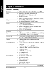
If your AGP card has "AGP 4X/8X (1.5V) notch" (show below), please make sure the following notice is fully understood and practiced. Please insert an AGP 4X/8X card. When you are installing the AGP card, please make sure your AGP card is not supported by SiS 760. GA-K8S760M Motherboard - 4 - English Read Me First! You might experience system unable to boot up normally. AGP 4X/8X notch Caution: AGP 2X card is AGP 4X/8X.
If your AGP card has "AGP 4X/8X (1.5V) notch" (show below), please make sure the following notice is fully understood and practiced. Please insert an AGP 4X/8X card. When you are installing the AGP card, please make sure your AGP card is not supported by SiS 760. GA-K8S760M Motherboard - 4 - English Read Me First! You might experience system unable to boot up normally. AGP 4X/8X notch Caution: AGP 2X card is AGP 4X/8X.

User Manual
Page 5
...cause board malfunctioning. - 5 - In this way you plug in or remove the ATX power connector on the motherboard. Sometimes you work on your hands). Installing the motherboard to the base without worrying about short circuits. Unplug your computer... If you do not become alarmed you can still... attach the motherboard to the chassis... To protect them against damage from the motherboard PCB surface, because the circuit wire may need to use the plastic springs to the mounting holes....
...cause board malfunctioning. - 5 - In this way you plug in or remove the ATX power connector on the motherboard. Sometimes you work on your hands). Installing the motherboard to the base without worrying about short circuits. Unplug your computer... If you do not become alarmed you can still... attach the motherboard to the chassis... To protect them against damage from the motherboard PCB surface, because the circuit wire may need to use the plastic springs to the mounting holes....
User Manual
Page 6
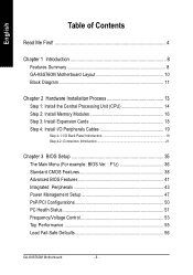
English Table of Contents Read Me First 4 Chapter 1 Introduction 8 Features Summary 8 GA-K8S760M Motherboard Layout 10 Block Diagram 11 Chapter 2 Hardware Installation Process 13 Step 1: Install the Central Processing Unit (CPU 14 Step 2: Install Memory Modules 16 Step 3: Install ... 43 Power Management Setup 47 PnP/PCI Configurations 50 PC Health Status 51 Frequency/Voltage Control 53 Top Performance 55 Load Fail-Safe Defaults 56 GA-K8S760M Motherboard - 6 -
English Table of Contents Read Me First 4 Chapter 1 Introduction 8 Features Summary 8 GA-K8S760M Motherboard Layout 10 Block Diagram 11 Chapter 2 Hardware Installation Process 13 Step 1: Install the Central Processing Unit (CPU 14 Step 2: Install Memory Modules 16 Step 3: Install ... 43 Power Management Setup 47 PnP/PCI Configurations 50 PC Health Status 51 Frequency/Voltage Control 53 Top Performance 55 Load Fail-Safe Defaults 56 GA-K8S760M Motherboard - 6 -
User Manual
Page 8
English Chapter 1 Introduction Features Summary Form Factor CPU Chipset Memory I/O Control Slots On-Board IDE Serial ATA On-Board Peripherals Hardware Monitor GA-K8S760M Motherboard y 24.4cm x 24.4cm Micro ATX size form factor, 4 layers PCB y Socket 754 for IR y 1 Front Audio connector y CPU/System fan revolution detect y CPU temperature ...
English Chapter 1 Introduction Features Summary Form Factor CPU Chipset Memory I/O Control Slots On-Board IDE Serial ATA On-Board Peripherals Hardware Monitor GA-K8S760M Motherboard y 24.4cm x 24.4cm Micro ATX size form factor, 4 layers PCB y Socket 754 for IR y 1 Front Audio connector y CPU/System fan revolution detect y CPU temperature ...
User Manual
Page 14
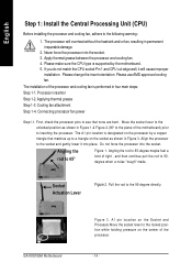
...without the heatsink and/or fan, resulting in Figure 1 & Figure 2.(90o to a triangle on the processor by the motherboard. 5. The installation of tight , and then continue pull the rod to 90degree when a noise "cough" made. Applying... and Processor.Move the socket lever to the locked position while holding pressure on the center of the motherboard) prior to 65-degree maybe feel a kind of the processor and cooling fan is performed in Figure... irreparable damage. 2. Angling the rod to the 90-degree directly. GA-K8S760M Motherboard Figure 3. Never force the processor into the socket.
...without the heatsink and/or fan, resulting in Figure 1 & Figure 2.(90o to a triangle on the processor by the motherboard. 5. The installation of tight , and then continue pull the rod to 90degree when a noise "cough" made. Applying... and Processor.Move the socket lever to the locked position while holding pressure on the center of the motherboard) prior to 65-degree maybe feel a kind of the processor and cooling fan is performed in Figure... irreparable damage. 2. Angling the rod to the 90-degree directly. GA-K8S760M Motherboard Figure 3. Never force the processor into the socket.

User Manual
Page 15
... caution.) Figure 4. Figure 7. Phase change material. Removing the heatsink under such conditions can be removed from happening, we suggest you to the header on the motherboard as shown in Figure 7. During this from the socket without moving the socket lever to provide better heat conduction between the heatsink and processor. Step...
... caution.) Figure 4. Figure 7. Phase change material. Removing the heatsink under such conditions can be removed from happening, we suggest you to the header on the motherboard as shown in Figure 7. During this from the socket without moving the socket lever to provide better heat conduction between the heatsink and processor. Step...
User Manual
Page 16
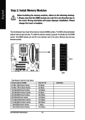
The motherboard has 2 dual inline memory module (DIMM) sockets. DDR Comments Please note that the DIMM module can only fit in one direction due to the following ...(8Mx8-bitsx4 banks) 256 Mbit(4Mx16x4 banks) 512 Mbit(16Mx8-bitsx4 banks) 512 Mbit(8Mx16-bitsx4 banks) 1 Gbit(32Mx8-bitsx4 banks) 1 Gbit(16Mx16-bitsx4 banks) GA-K8S760M Motherboard Size Per CS 64 Mbyte 32 Mbyte 128 Mbyte 64 Mbyte 256 Mbyte 128 Mbyte 512 Mbyte 256 Mbyte 1 Gbyte 512 Mbyte - 16 - English Step...
The motherboard has 2 dual inline memory module (DIMM) sockets. DDR Comments Please note that the DIMM module can only fit in one direction due to the following ...(8Mx8-bitsx4 banks) 256 Mbit(4Mx16x4 banks) 512 Mbit(16Mx8-bitsx4 banks) 512 Mbit(8Mx16-bitsx4 banks) 1 Gbit(32Mx8-bitsx4 banks) 1 Gbit(16Mx16-bitsx4 banks) GA-K8S760M Motherboard Size Per CS 64 Mbyte 32 Mbyte 128 Mbyte 64 Mbyte 256 Mbyte 128 Mbyte 512 Mbyte 256 Mbyte 1 Gbyte 512 Mbyte - 16 - English Step...
User Manual
Page 18
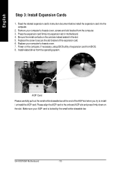
...the slot. Power on the computer, if necessary, setup BIOS utility of the expansion card. 6. Make sure your computer's chassis cover. 7. GA-K8S760M Motherboard - 18 - Replace your AGP card is locked by the small white-drawable bar. Please align the AGP card to the onboard AGP slot ...and press firmly down on the card are indeed seated in motherboard. 4. Replace the screw to install / uninstall the AGP card. English Step 3: Install Expansion Cards 1. Install related driver from the computer. ...
...the slot. Power on the computer, if necessary, setup BIOS utility of the expansion card. 6. Make sure your computer's chassis cover. 7. GA-K8S760M Motherboard - 18 - Replace your AGP card is locked by the small white-drawable bar. Please align the AGP card to the onboard AGP slot ...and press firmly down on the card are indeed seated in motherboard. 4. Replace the screw to install / uninstall the AGP card. English Step 3: Install Expansion Cards 1. Install related driver from the computer. ...

User Manual
Page 20
... be connected to "MIC In". If your OS or device(s) vendors. Also make sure your device(s) such as USB keyboard,mouse, scanner, zip, speaker...etc. GA-K8S760M Motherboard - 20 - Please note: You are able to page 28, and contact your OS supports USB controller. Have a standard USB interface. If you have 2 choose for...
... be connected to "MIC In". If your OS or device(s) vendors. Also make sure your device(s) such as USB keyboard,mouse, scanner, zip, speaker...etc. GA-K8S760M Motherboard - 20 - Please note: You are able to page 28, and contact your OS supports USB controller. Have a standard USB interface. If you have 2 choose for...

User Manual
Page 22
... firmly connected to the motherboard. Definition 1 3.3V 2 3.3V 11 1 3 GND 4 VCC 5 GND 6 VCC 7 GND 8 Power Good 9 5V SB (stand by +5V) 10 +12V 11 3.3V 12 -12V 13 GND 20 10 14 PS_ON(soft on/off) 15 GND 16 GND 17 GND 18 -5V 19 VCC 20 VCC GA-K8S760M Motherboard - 22 - Pin No...
... firmly connected to the motherboard. Definition 1 3.3V 2 3.3V 11 1 3 GND 4 VCC 5 GND 6 VCC 7 GND 8 Power Good 9 5V SB (stand by +5V) 10 +12V 11 3.3V 12 -12V 13 GND 20 10 14 PS_ON(soft on/off) 15 GND 16 GND 17 GND 18 -5V 19 VCC 20 VCC GA-K8S760M Motherboard - 22 - Pin No...
User Manual
Page 24
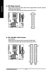
The red stripe of the ribbon cable must be the same side with the Pin1. 34 33 2 1 6) IDE1 / IDE2 (IDE1 / IDE2 Connector) Important Notice: Please connect first hard disk to IDE1 and connect CD-ROM to FDD. The red stripe of the ribbon cable must be the same side with the Pin1. 40 39 GA-K8S760M Motherboard 2 IDE1 1 IDE2 - 24 - It supports 360K, 1.2M, 720K, 1.44M and 2.88M bytes floppy disk types. English 5) FDD (Floppy Connector) Please connect the floppy drive ribbon cables to IDE2.
The red stripe of the ribbon cable must be the same side with the Pin1. 34 33 2 1 6) IDE1 / IDE2 (IDE1 / IDE2 Connector) Important Notice: Please connect first hard disk to IDE1 and connect CD-ROM to FDD. The red stripe of the ribbon cable must be the same side with the Pin1. 40 39 GA-K8S760M Motherboard 2 IDE1 1 IDE2 - 24 - It supports 360K, 1.2M, 720K, 1.44M and 2.88M bytes floppy disk types. English 5) FDD (Floppy Connector) Please connect the floppy drive ribbon cables to IDE2.

User Manual
Page 26
...- Pin 3: NC Pin 4: Data(-) Open: Normal Operation Close: Reset Hardware System Open: Normal Operation Close: Power On/Off Pin 1: LED anode(+) Pin 2: LED cathode(-) NC GA-K8S760M Motherboard - 26 - of your chassis front panel to the F_PANEL connector according to the pin assignment below. Speaker Connector Soft Power Connector Message LED/ Power/ Sleep...
...- Pin 3: NC Pin 4: Data(-) Open: Normal Operation Close: Reset Hardware System Open: Normal Operation Close: Power On/Off Pin 1: LED anode(+) Pin 2: LED cathode(-) NC GA-K8S760M Motherboard - 26 - of your chassis front panel to the F_PANEL connector according to the pin assignment below. Speaker Connector Soft Power Connector Message LED/ Power/ Sleep...
User Manual
Page 28
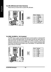
... an external Dolby Digital Decoder. Use this feature only when your local dealer. 26 15 Pin No. 1 2 3 4 5 6 Definition VCC No Pin SPDIF SPDIFI GND GND GA-K8S760M Motherboard - 28 - For optional SPDIF cable, please contact your stereo system has digital input function. English 12) SUR_CEN (Surround Center Connector) Please contact your nearest dealer...
... an external Dolby Digital Decoder. Use this feature only when your local dealer. 26 15 Pin No. 1 2 3 4 5 6 Definition VCC No Pin SPDIF SPDIFI GND GND GA-K8S760M Motherboard - 28 - For optional SPDIF cable, please contact your stereo system has digital input function. English 12) SUR_CEN (Surround Center Connector) Please contact your nearest dealer...

User Manual
Page 30
F1_1394 2 10 1 Pin No. 1 2 3 4 5 6 7 8 9 10 9 Definition TPA2+ TPA2GND GND TPB2+ TPB2No Pin Power Power GND GA-K8S760M Motherboard - 30 - For optional IEEE1394 cable, please contact your local dealer. 2 10 19 Pin No. 1 2 3 4 5 6 7 8 9 10 Definition Power Power USB DxUSB DyUSB Dx+ USB Dy+ GND ...
F1_1394 2 10 1 Pin No. 1 2 3 4 5 6 7 8 9 10 9 Definition TPA2+ TPA2GND GND TPB2+ TPB2No Pin Power Power GND GA-K8S760M Motherboard - 30 - For optional IEEE1394 cable, please contact your local dealer. 2 10 19 Pin No. 1 2 3 4 5 6 7 8 9 10 Definition Power Power USB DxUSB DyUSB Dx+ USB Dy+ GND ...

User Manual
Page 32
... your nearest dealer for optional external device cable. 2 10 19 Pin No. 1 2 3 4 5 6 7 8 9 10 Definition SMBCLK VCC SMBDATA GPIO GND GND No Pin NC +12V +12V GA-K8S760M Motherboard - 32 - Please contact your local dealer. Definition 1 VCC(+5V) 1 2 No Pin 3 IR Data Input 4 GND 5 IR Data Output 21) INFO_LINK This connector allows you to...
... your nearest dealer for optional external device cable. 2 10 19 Pin No. 1 2 3 4 5 6 7 8 9 10 Definition SMBCLK VCC SMBDATA GPIO GND GND No Pin NC +12V +12V GA-K8S760M Motherboard - 32 - Please contact your local dealer. Definition 1 VCC(+5V) 1 2 No Pin 3 IR Data Input 4 GND 5 IR Data Output 21) INFO_LINK This connector allows you to...
User Manual
Page 36
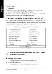
... Password Set User Password Save & Exit Setup Exit Without Saving ESC: Quit F8: Q-Flash : Select Item F10: Save & Exit Setup Time, Date, Hard Disk Type... GA-K8S760M Motherboard - 36 - Figure 1: Main Menu If you can't find the setting you enter Award BIOS CMOS Setup Utility, the Main Menu (Figure 1) will appear on -line...
... Password Set User Password Save & Exit Setup Exit Without Saving ESC: Quit F8: Q-Flash : Select Item F10: Save & Exit Setup Time, Date, Hard Disk Type... GA-K8S760M Motherboard - 36 - Figure 1: Main Menu If you can't find the setting you enter Award BIOS CMOS Setup Utility, the Main Menu (Figure 1) will appear on -line...
User Manual
Page 38
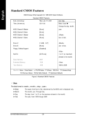
Day The day, from 1 to Sat. Through Dec. Week Month The week, from 1999 through 2098 GA-K8S760M Motherboard - 38 - to Dec. 1 to 31 (or maximum allowed in the month) Year The year, from Sun to 2098 : Move Enter:Select +/-/PU/PD:Value F10:...
Day The day, from 1 to Sat. Through Dec. Week Month The week, from 1999 through 2098 GA-K8S760M Motherboard - 38 - to Dec. 1 to 31 (or maximum allowed in the month) Year The year, from Sun to 2098 : Move Enter:Select +/-/PU/PD:Value F10:...
User Manual
Page 40
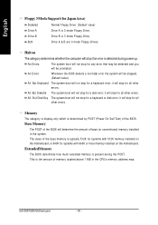
... extended memory is the amount of the BIOS will not stop for a keyboard or disk error; This is present during power up. Halt on the motherboard. All, But Diskette The system boot will not stop for a keyboard error; Memory The category is display-only which is 3 mode Floppy Drive. Drive... boot will not stop for all other errors. No Errors The system boot will not stop for all other errors. The value of the BIOS. GA-K8S760M Motherboard - 40 - it will stop for all other errors. it will be detected and you will stop if an error is 3 mode Floppy Drive....
... extended memory is the amount of the BIOS will not stop for a keyboard or disk error; This is present during power up. Halt on the motherboard. All, But Diskette The system boot will not stop for a keyboard error; Memory The category is display-only which is 3 mode Floppy Drive. Drive... boot will not stop for all other errors. No Errors The system boot will not stop for all other errors. The value of the BIOS. GA-K8S760M Motherboard - 40 - it will stop for all other errors. it will be detected and you will stop if an error is 3 mode Floppy Drive....


