
Manual
Page 1
GA-MA785GPM-UD2H/ GA-MA785GM-UD2H/ GA-MA785GM-US2H AM2+/AM2 socket motherboard for AMD Phenom™ II processor/ AMD Phenom™ processor/ AMD Athlon™ II processor/ AMD Athlon™ processor/ AMD Sempron™ processor User's Manual Rev. 1001 12ME-MA785M2-1001R
GA-MA785GPM-UD2H/ GA-MA785GM-UD2H/ GA-MA785GM-US2H AM2+/AM2 socket motherboard for AMD Phenom™ II processor/ AMD Phenom™ processor/ AMD Athlon™ II processor/ AMD Athlon™ processor/ AMD Sempron™ processor User's Manual Rev. 1001 12ME-MA785M2-1001R

Manual
Page 3
... Identifying Your Motherboard Revision The revision number on our website. Check your motherboard looks like this product, GIGABYTE provides the following types of documentations: For quick set-up of GIGABYTE. All rights reserved. The trademarks mentioned in this manual is protected by copyright laws and is 1.0. Disclaimer Information in any form or by...
... Identifying Your Motherboard Revision The revision number on our website. Check your motherboard looks like this product, GIGABYTE provides the following types of documentations: For quick set-up of GIGABYTE. All rights reserved. The trademarks mentioned in this manual is protected by copyright laws and is 1.0. Disclaimer Information in any form or by...

Manual
Page 5
k Only for GA-MA785GPM-UD2H. Chapter 3 Drivers Installation 61 3-1 Installing Chipset Drivers 61 3-2 Application Software 62 3-3 Technical Manuals 62 3-4 Contact...63 3-5 System...63 3-6 Download Center 64 Chapter 4 Unique Features 65 4-1 Xpress Recovery2 65 4-2 BIOS Update Utilities 68 4-2-1 Updating the BIOS with the Q-Flash ... Functionjk 92 5-2-4 Configuring Microphone Recording 93 5-2-5 Using the Sound Recorder 95 5-3 Troubleshooting 96 5-3-1 Frequently Asked Questions 96 5-3-2 Troubleshooting Procedure 97 5-4 Regulatory Statements 99 j Only for GA-MA785GM-UD2H. - 5 -
k Only for GA-MA785GPM-UD2H. Chapter 3 Drivers Installation 61 3-1 Installing Chipset Drivers 61 3-2 Application Software 62 3-3 Technical Manuals 62 3-4 Contact...63 3-5 System...63 3-6 Download Center 64 Chapter 4 Unique Features 65 4-1 Xpress Recovery2 65 4-2 BIOS Update Utilities 68 4-2-1 Updating the BIOS with the Q-Flash ... Functionjk 92 5-2-4 Configuring Microphone Recording 93 5-2-5 Using the Sound Recorder 95 5-3 Troubleshooting 96 5-3-1 Frequently Asked Questions 96 5-3-2 Troubleshooting Procedure 97 5-4 Regulatory Statements 99 j Only for GA-MA785GM-UD2H. - 5 -

Manual
Page 6
... (Part No. 12CR1-1SPINO-1*R) COM port cable (Part No. 12CF1-1CM001-3*R) LPT port cable (Part No. 12CF1-1LP001-0*R) - 6 - Box Contents GA-MA785GPM-UD2H, GA-MA785GM-UD2H, or GA-MA785GM-US2H motherboard Motherboard driver disk User's Manual Quick Installation Guide One IDE cable Two SATA 3Gb/s cables I/O Shield • The box contents above are subject to change without...
... (Part No. 12CR1-1SPINO-1*R) COM port cable (Part No. 12CF1-1CM001-3*R) LPT port cable (Part No. 12CF1-1LP001-0*R) - 6 - Box Contents GA-MA785GPM-UD2H, GA-MA785GM-UD2H, or GA-MA785GM-US2H motherboard Motherboard driver disk User's Manual Quick Installation Guide One IDE cable Two SATA 3Gb/s cables I/O Shield • The box contents above are subject to change without...
Manual
Page 9
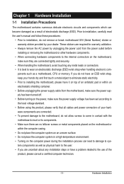
.... • Before using the product, please verify that all cables and power connectors of your dealer. Hardware Installation Prior to installation, carefully read the user's manual and follow these procedures: • Prior to installation, do not allow screws to come in contact with the motherboard circuit or its components. • Make...
.... • Before using the product, please verify that all cables and power connectors of your dealer. Hardware Installation Prior to installation, carefully read the user's manual and follow these procedures: • Prior to installation, do not allow screws to come in contact with the motherboard circuit or its components. • Make...
Manual
Page 15
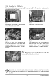
... the steps below to correctly install the CPU cooler on the CPU. (The following procedure uses the GIGABYTE cooler as the picture above shows) to lock into place. (Refer to your CPU cooler installation manual for instructions on installing the cooler.) Step 5: Finally, attach the power connector of the installed CPU. Step...
... the steps below to correctly install the CPU cooler on the CPU. (The following procedure uses the GIGABYTE cooler as the picture above shows) to lock into place. (Refer to your CPU cooler installation manual for instructions on installing the cooler.) Step 5: Finally, attach the power connector of the installed CPU. Step...

Manual
Page 18
Carefully read the manual that supports your expansion card. • Always turn off the computer and unplug the power cord from the power outlet before you begin to install ...
Carefully read the manual that supports your expansion card. • Always turn off the computer and unplug the power cord from the power outlet before you begin to install ...

Manual
Page 33
... lost. You may cause damage to the motherboard. • After system restart, go to BIOS Setup to load factory defaults (select Load Optimized Defaults) or manually configure the BIOS settings (refer to Chapter 2, "BIOS Setup," for BIOS configurations). 20) BATTERY The battery provides power to touch the two pins for 5 seconds...
... lost. You may cause damage to the motherboard. • After system restart, go to BIOS Setup to load factory defaults (select Load Optimized Defaults) or manually configure the BIOS settings (refer to Chapter 2, "BIOS Setup," for BIOS configurations). 20) BATTERY The battery provides power to touch the two pins for 5 seconds...
Manual
Page 39
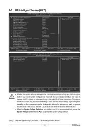
... Control SouthBridge Volt Control SidePort Mem Volt Control [Press Enter] [Auto] [Auto] [Auto] [Auto] 200 [Auto] [Disabled] 500 [Auto] x4.00 800Mhz [Unganged] [Press Enter] [Manual] [Normal] [Normal] [Normal] [Normal] Item Help Menu Level Move Enter: Select F5: Previous Values +/-/PU/PD: Value F10: Save F6: Fail-Safe Defaults ESC...
... Control SouthBridge Volt Control SidePort Mem Volt Control [Press Enter] [Auto] [Auto] [Auto] [Auto] 200 [Auto] [Disabled] 500 [Auto] x4.00 800Mhz [Unganged] [Press Enter] [Manual] [Normal] [Normal] [Normal] [Normal] Item Help Menu Level Move Enter: Select F5: Previous Values +/-/PU/PD: Value F10: Save F6: Fail-Safe Defaults ESC...
Manual
Page 40
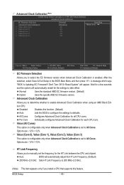
.... Wait for a few seconds and the system will automatically restart for the HT Link between the CPU and chipset. Advanced Clock Calibration Allows you to manually set the frequency for the settings to take effect. Normal Uses the standard AMD EC firmware version. (Default) Hybrid Uses the specific AMD EC firmware...
.... Wait for a few seconds and the system will automatically restart for the HT Link between the CPU and chipset. Advanced Clock Calibration Allows you to manually set the frequency for the settings to take effect. Normal Uses the standard AMD EC firmware version. (Default) Hybrid Uses the specific AMD EC firmware...

Manual
Page 41
... values to reset the board to X5.33. CPU NorthBridge Freq. (Note) Allows you use an AM2 CPU: DDR 400 Sets Memory Clock to manually set the memory clock as required. The adjustable range is enabled. PCIE Clock(MHz) Allows you to DDR 400. Auto sets the PCIe clock frequency... to Manual. This item is configurable only if the VGA Core Clock control option is dependent on the CPU being used . Set Memory Clock Determines whether to...
... values to reset the board to X5.33. CPU NorthBridge Freq. (Note) Allows you use an AM2 CPU: DDR 400 Sets Memory Clock to manually set the memory clock as required. The adjustable range is enabled. PCIE Clock(MHz) Allows you to DDR 400. Auto sets the PCIe clock frequency... to Manual. This item is configurable only if the VGA Core Clock control option is dependent on the CPU being used . Set Memory Clock Determines whether to...
Manual
Page 42
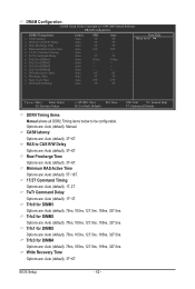
.../PD: Value F10: Save F6: Fail-Safe Defaults ESC: Exit F1: General Help F7: Optimized Defaults DDRII Timing Items Manual allows all DDR2 Timing items below to CAS R/W Delay Options are : Auto (default), Manual. TwTr Command Delay Options are : Auto (default), 1T, 2T. Minimum RAS Active Time Options are: Auto (default), 5T...
.../PD: Value F10: Save F6: Fail-Safe Defaults ESC: Exit F1: General Help F7: Optimized Defaults DDRII Timing Items Manual allows all DDR2 Timing items below to CAS R/W Delay Options are : Auto (default), Manual. TwTr Command Delay Options are : Auto (default), 1T, 2T. Minimum RAS Active Time Options are: Auto (default), 5T...
Manual
Page 43
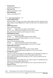
.... Normal Supplies the SidePort memory voltage as required. CPU Voltage Control Allows you to set the SidePort memory voltage. Manual allows all voltage control items below to be configurable. (Default: Manual) DDR2 Voltage Control Allows you to set memory voltage. Note: Increasing memory voltage may result in damage to your ...reduce the useful life of the CPU. Precharge Time Options are : Auto (default), 2T~5T. ******** System Voltage Optimized ******** System Voltage Control Determines whether to manually set the system voltages. Row Cycle Time Options are: Auto (default), 11T~26T.
.... Normal Supplies the SidePort memory voltage as required. CPU Voltage Control Allows you to set the SidePort memory voltage. Manual allows all voltage control items below to be configurable. (Default: Manual) DDR2 Voltage Control Allows you to set memory voltage. Note: Increasing memory voltage may result in damage to your ...reduce the useful life of the CPU. Precharge Time Options are : Auto (default), 2T~5T. ******** System Voltage Optimized ******** System Voltage Control Determines whether to manually set the system voltages. Row Cycle Time Options are: Auto (default), 11T~26T.
Manual
Page 45
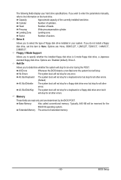
... the MS-DOS operating system. If you do not install a floppy disk drive, set this item to None. If you wish to enter the parameters manually, refer to determine whether the system will be reserved for all other errors. Floppy 3 Mode Support Allows you to the information on the hard drive...
... the MS-DOS operating system. If you do not install a floppy disk drive, set this item to None. If you wish to enter the parameters manually, refer to determine whether the system will be reserved for all other errors. Floppy 3 Mode Support Allows you to the information on the hard drive...

Manual
Page 61
.... • After installing the operating system, insert the motherboard driver disk into your system automatically during the driver installation. Or click Install Single Items to manually select the drivers you wish to do so may affect the driver installation. • Some device drivers will then autodetect and install the USB 2.0 driver...
.... • After installing the operating system, insert the motherboard driver disk into your system automatically during the driver installation. Or click Install Single Items to manually select the drivers you wish to do so may affect the driver installation. • Some device drivers will then autodetect and install the USB 2.0 driver...
Manual
Page 62
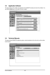
You can click the Install button on the right of an item to install it. 3-3 Technical Manuals This page provides GIGABYTE's application guides, content descriptions for this driver disk, and the motherboard manuals. 3-2 Application Software This page displays all the utilities and applications that GIGABYTE develops and some free software. Drivers Installation - 62 -
You can click the Install button on the right of an item to install it. 3-3 Technical Manuals This page provides GIGABYTE's application guides, content descriptions for this driver disk, and the motherboard manuals. 3-2 Application Software This page displays all the utilities and applications that GIGABYTE develops and some free software. Drivers Installation - 62 -
Manual
Page 68
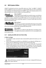
...copy the BIOS file to the main BIOS to enter Q-Flash. Before You Begin 1. From GIGABYTE's website, download the latest compressed BIOS update file that support DualBIOS have two BIOS onboard, a...by adding one more physical BIOS chip. During the POST, press the key to ensure normal system operation. GA-MA785GPM-UD2H E3c . . . . : BIOS Setup : XpressRecovery2 : Boot Menu : Qflash 06/05/2009-RS785-..., or hard drive. For the sake of system safety, users cannot update the backup BIOS manually. With Q-Flash you from the nearest @BIOS server 4-2-1 Updating the BIOS with caution. site...
...copy the BIOS file to the main BIOS to enter Q-Flash. Before You Begin 1. From GIGABYTE's website, download the latest compressed BIOS update file that support DualBIOS have two BIOS onboard, a...by adding one more physical BIOS chip. During the POST, press the key to ensure normal system operation. GA-MA785GPM-UD2H E3c . . . . : BIOS Setup : XpressRecovery2 : Boot Menu : Qflash 06/05/2009-RS785-..., or hard drive. For the sake of system safety, users cannot update the backup BIOS manually. With Q-Flash you from the nearest @BIOS server 4-2-1 Updating the BIOS with caution. site...

Manual
Page 71
... after the system restarts. If the BIOS update file for example, avoid a power loss or switching off the Internet). Do not use the G.O.M. (GIGABYTE Online Management) function when using @BIOS. 4. Using @BIOS 1. Make sure that the BIOS file to be flashed matches your system not to your ...location and then download the BIOS file that matches your motherboard is not present on the @BIOS server site, please manually download the BIOS update file from GIGABYTE's website and follow the instructions in a corrupted BIOS or a system that is stable and do so may result in "...
... after the system restarts. If the BIOS update file for example, avoid a power loss or switching off the Internet). Do not use the G.O.M. (GIGABYTE Online Management) function when using @BIOS. 4. Using @BIOS 1. Make sure that the BIOS file to be flashed matches your system not to your ...location and then download the BIOS file that matches your motherboard is not present on the @BIOS server site, please manually download the BIOS update file from GIGABYTE's website and follow the instructions in a corrupted BIOS or a system that is stable and do so may result in "...
Manual
Page 80
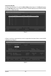
... Advanced Micro Devices, Inc. LD No RAID Mode [ Define LD Menu ] Total Drv LD 1 RAID 0 0 Stripe Block: 64 KB Gigabyte Boundary: ON [ Drives Assignments ] Channel:ID Drive Model 1:Mas WDC WD800JD-22LSA0 2:Mas WDC WD800JD-22LSA0 Capabilities SATA 3G SATA 3G Fast Init... 7 ---- LD 10 ---- The Define LD selection from the Main Menu allows users to enter the RAID configuration menu (Figure 5). Create Arrays Manually To create a new array, press to enter the Define LD Menu window (Figure 4). LD 4 ---- LD 8 ---- LD 6 ---- Option...
... Advanced Micro Devices, Inc. LD No RAID Mode [ Define LD Menu ] Total Drv LD 1 RAID 0 0 Stripe Block: 64 KB Gigabyte Boundary: ON [ Drives Assignments ] Channel:ID Drive Model 1:Mas WDC WD800JD-22LSA0 2:Mas WDC WD800JD-22LSA0 Capabilities SATA 3G SATA 3G Fast Init... 7 ---- LD 10 ---- The Define LD selection from the Main Menu allows users to enter the RAID configuration menu (Figure 5). Create Arrays Manually To create a new array, press to enter the Define LD Menu window (Figure 4). LD 4 ---- LD 8 ---- LD 6 ---- Option...
Manual
Page 88
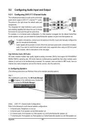
...) HD Audio includes multiple high quality digital-to-analog converters (DACs) that allow multiple audio streams (in and out) to the Mic in jack and manually configure the jack for each jack through the audio driver. The picture to change Center/Subwoofer Speaker Out Rear Speaker Out Side Speaker Out Line...
...) HD Audio includes multiple high quality digital-to-analog converters (DACs) that allow multiple audio streams (in and out) to the Mic in jack and manually configure the jack for each jack through the audio driver. The picture to change Center/Subwoofer Speaker Out Rear Speaker Out Side Speaker Out Line...


