
Manual
Page 1
GA-MA790GPT-UD3H AM3 socket motherboard for AMD Phenom™ II processor/AMD Athlon™ II processor User's Manual Rev. 1002 12ME-MA79PT3-1002R
GA-MA790GPT-UD3H AM3 socket motherboard for AMD Phenom™ II processor/AMD Athlon™ II processor User's Manual Rev. 1002 12ME-MA79PT3-1002R

Manual
Page 3
... laws and is 1.0. For product-related information, check on our website at: http://www.gigabyte.com.tw Identifying Your Motherboard Revision The revision number on your motherboard revision before updating motherboard BIOS, drivers, or when looking for technical information. For example, "REV: 1.0" means ...order to the specifications and features in this product, GIGABYTE provides the following types of documentations: For quick set-up of the product, read or download the information on/from the Support&Downloads\Motherboard\Technology Guide page on how to their respective owners...
... laws and is 1.0. For product-related information, check on our website at: http://www.gigabyte.com.tw Identifying Your Motherboard Revision The revision number on your motherboard revision before updating motherboard BIOS, drivers, or when looking for technical information. For example, "REV: 1.0" means ...order to the specifications and features in this product, GIGABYTE provides the following types of documentations: For quick set-up of the product, read or download the information on/from the Support&Downloads\Motherboard\Technology Guide page on how to their respective owners...

Manual
Page 4
Table of Contents Box Contents...6 Optional Items...6 GA-MA790GPT-UD3H Motherboard Layout 7 Block Diagram...8 Chapter 1 Hardware Installation 9 1-1 Installation Precautions 9 1-2 Product Specifications 10 1-3 Installing the CPU and CPU Cooler 13 1-3-1 Installing the CPU 13 1-3-2 Installing the CPU ...
Table of Contents Box Contents...6 Optional Items...6 GA-MA790GPT-UD3H Motherboard Layout 7 Block Diagram...8 Chapter 1 Hardware Installation 9 1-1 Installation Precautions 9 1-2 Product Specifications 10 1-3 Installing the CPU and CPU Cooler 13 1-3-1 Installing the CPU 13 1-3-2 Installing the CPU ...

Manual
Page 6
The box contents are for reference only. Box Contents GA-MA790GPT-UD3H motherboard Motherboard driver disk User's Manual Quick Installation Guide One IDE cable Two SATA 3Gb/s cables I/O Shield • The box contents above are subject to change without notice. • The motherboard image is for reference only and the actual items shall depend on the product...
The box contents are for reference only. Box Contents GA-MA790GPT-UD3H motherboard Motherboard driver disk User's Manual Quick Installation Guide One IDE cable Two SATA 3Gb/s cables I/O Shield • The box contents above are subject to change without notice. • The motherboard image is for reference only and the actual items shall depend on the product...

Manual
Page 7
GA-MA790GPT-UD3H Motherboard Layout KB_USB CPU_FAN ATX VGA_DVI ATX_12V_2X4 Socket AM3 HDMI OPTICAL USB_1394 USB_LAN PWR_FAN F_USB1 F_USB2 F_USB3 DDR3_1 DDR3_2 DDR3_3 DDR3_4 AUDIO SidePort F_AUDIO PCIEX1_1 AMD 790GX Meory IDE NB_FAN RTL8111C PCIEX16_1 CD_IN PCIEX1_2 PCIEX1_3 GA-MA790GPT-UD3H AMD SB750 BATTERY CLR_CMOS M_BIOS B_BIOS CODEC SPDIF_OUT PCIEX8_1 SPDIF_IN PCI1 TSB43AB23 SYS_FAN1 SATA2_4 SATA2_5 SATA2_2 SATA2_3 IT8718 PCI2 SATA2_0 SATA2_1 SYS_FAN2 COM CI F_PANEL FDD F_1394_1 F_1394_2 PWR_LED - 7 -
GA-MA790GPT-UD3H Motherboard Layout KB_USB CPU_FAN ATX VGA_DVI ATX_12V_2X4 Socket AM3 HDMI OPTICAL USB_1394 USB_LAN PWR_FAN F_USB1 F_USB2 F_USB3 DDR3_1 DDR3_2 DDR3_3 DDR3_4 AUDIO SidePort F_AUDIO PCIEX1_1 AMD 790GX Meory IDE NB_FAN RTL8111C PCIEX16_1 CD_IN PCIEX1_2 PCIEX1_3 GA-MA790GPT-UD3H AMD SB750 BATTERY CLR_CMOS M_BIOS B_BIOS CODEC SPDIF_OUT PCIEX8_1 SPDIF_IN PCI1 TSB43AB23 SYS_FAN1 SATA2_4 SATA2_5 SATA2_2 SATA2_3 IT8718 PCI2 SATA2_0 SATA2_1 SYS_FAN2 COM CI F_PANEL FDD F_1394_1 F_1394_2 PWR_LED - 7 -

Manual
Page 9
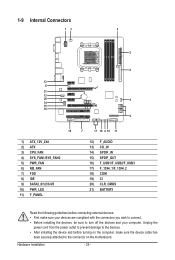
.... • Always remove the AC power by your hardware components are connected. • To prevent damage to the motherboard, do not remove or break motherboard S/N (Serial Number) sticker or warranty sticker provided by unplugging the power cord from the power outlet before installing or... the product, please consult a certified computer technician. - 9 - If you are connected tightly and securely. • When handling the motherboard, avoid touching any installation steps or have a problem related to wear an electrostatic discharge (ESD) wrist strap when handling electronic com-
.... • Always remove the AC power by your hardware components are connected. • To prevent damage to the motherboard, do not remove or break motherboard S/N (Serial Number) sticker or warranty sticker provided by unplugging the power cord from the power outlet before installing or... the product, please consult a certified computer technician. - 9 - If you are connected tightly and securely. • When handling the motherboard, avoid touching any installation steps or have a problem related to wear an electrostatic discharge (ESD) wrist strap when handling electronic com-
Manual
Page 12
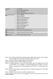
... x8 mode. (Note 5) Whether the CPU/system fan speed control function is to be installed, be sure to install it in EasyTune may differ by motherboard model. The PCIEX8_1 slot shares bandwidth with a PCI Express graphics card, the PCIEX16_1 slot will depend on the CPU/system cooler you install. (Note 6) Available...
... x8 mode. (Note 5) Whether the CPU/system fan speed control function is to be installed, be sure to install it in EasyTune may differ by motherboard model. The PCIEX8_1 slot shares bandwidth with a PCI Express graphics card, the PCIEX16_1 slot will depend on the CPU/system cooler you install. (Note 6) Available...

Manual
Page 13
Locate the pin one of thermal grease on the computer if the CPU cooler is not recommended that the motherboard supports the CPU. (Go to GIGABYTE's website for the peripherals. 1-3 Installing the CPU and CPU Cooler Read the following guidelines before installing the CPU to your hardware specifications including the CPU, ...
Locate the pin one of thermal grease on the computer if the CPU cooler is not recommended that the motherboard supports the CPU. (Go to GIGABYTE's website for the peripherals. 1-3 Installing the CPU and CPU Cooler Read the following guidelines before installing the CPU to your hardware specifications including the CPU, ...

Manual
Page 14
... socket and gently insert the CPU into the fully locked position. Hardware Installation - 14 - Follow the steps below to correctly install the CPU into the motherboard CPU socket. • Before installing the CPU, make sure to turn off the computer and unplug the power cord from the power outlet to prevent...
... socket and gently insert the CPU into the fully locked position. Hardware Installation - 14 - Follow the steps below to correctly install the CPU into the motherboard CPU socket. • Before installing the CPU, make sure to turn off the computer and unplug the power cord from the power outlet to prevent...

Manual
Page 15
... to the CPU. 1-3-2 Installing the CPU Cooler Follow the steps below to correctly install the CPU cooler on the CPU. (The following procedure uses the GIGABYTE cooler as the picture above shows) to lock into place. (Refer to your CPU cooler installation manual for instructions on installing the cooler.) Step 5: Finally..., attach the power connector of the CPU cooler to the CPU fan header (CPU_FAN) on the motherboard. Step 4: Turn the cam handle from the left side to the mounting lug on the CPU.
... to the CPU. 1-3-2 Installing the CPU Cooler Follow the steps below to correctly install the CPU cooler on the CPU. (The following procedure uses the GIGABYTE cooler as the picture above shows) to lock into place. (Refer to your CPU cooler installation manual for instructions on installing the cooler.) Step 5: Finally..., attach the power connector of the CPU cooler to the CPU fan header (CPU_FAN) on the motherboard. Step 4: Turn the cam handle from the left side to the mounting lug on the CPU.

Manual
Page 16
...or four memory modules, it is installed, the BIOS will double the original memory bandwidth. After the memory is recommended that the motherboard supports the memory. Dual Channel mode cannot be used and installed in only one DDR3 memory module is recommended that memory of ..., brand, speed, and chips be enabled if only one direction. Hardware Installation - 16 - A memory module can be used . (Go to GIGABYTE's website for optimum performance. 1-4 Installing the Memory Read the following guidelines before you begin to install the memory: • Make sure that you ...
...or four memory modules, it is installed, the BIOS will double the original memory bandwidth. After the memory is recommended that the motherboard supports the memory. Dual Channel mode cannot be used and installed in only one DDR3 memory module is recommended that memory of ..., brand, speed, and chips be enabled if only one direction. Hardware Installation - 16 - A memory module can be used . (Go to GIGABYTE's website for optimum performance. 1-4 Installing the Memory Read the following guidelines before you begin to install the memory: • Make sure that you ...

Manual
Page 17
... damage to correctly install your fingers on the memory and insert it can only fit in the memory sockets. Place the memory module on this motherboard. Notch DDR3 DIMM A DDR3 memory module has a notch, so it vertically into place when the memory module is securely inserted. - 17 - Step 2: The clips at...
... damage to correctly install your fingers on the memory and insert it can only fit in the memory sockets. Place the memory module on this motherboard. Notch DDR3 DIMM A DDR3 memory module has a notch, so it vertically into place when the memory module is securely inserted. - 17 - Step 2: The clips at...

Manual
Page 18
... the slot and then lift the card straight out from the power outlet before you begin to install an expansion card: • Make sure the motherboard supports the expansion card. Secure the card's metal bracket to the chassis back panel with the expansion card in the expansion slot. 1. Install the driver...
... the slot and then lift the card straight out from the power outlet before you begin to install an expansion card: • Make sure the motherboard supports the expansion card. Secure the card's metal bracket to the chassis back panel with the expansion card in the expansion slot. 1. Install the driver...

Manual
Page 19
... on the PCIEX16_1 slot. Hardware Installation 1-6 Setup of identical brand and chip and correct driver - Refer to the manual of the two cards. A CrossFireX-supported motherboard with sufficient power is selected. (Note) The bridge connectors may differ by graphics cards. Connecting the Graphics Cards Step 1: Observe the steps in "1-5 Installing an...
... on the PCIEX16_1 slot. Hardware Installation 1-6 Setup of identical brand and chip and correct driver - Refer to the manual of the two cards. A CrossFireX-supported motherboard with sufficient power is selected. (Note) The bridge connectors may differ by graphics cards. Connecting the Graphics Cards Step 1: Observe the steps in "1-5 Installing an...
Manual
Page 20
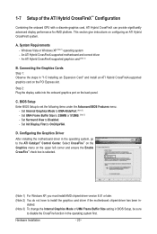
...Note 1) operating system - C. D. Select CrossFire™ on the Graphics menu on the PCI Express slot. An ATI Hybrid CrossFireX-supported motherboard and correct driver - Set Internal Graphics Mode to set the following items under the Advanced BIOS Features menu: - System Requirements - BIOS ...in BIOS Setup, be sure to install the graphics card driver if the motherboard chipset driver has been in the operating system first. Configuring the Graphics Driver After installing the motherboard driver in "1-5 Installing an Expansion Card" and install an ATI Hybrid ...
...Note 1) operating system - C. D. Select CrossFire™ on the Graphics menu on the PCI Express slot. An ATI Hybrid CrossFireX-supported motherboard and correct driver - Set Internal Graphics Mode to set the following items under the Advanced BIOS Features menu: - System Requirements - BIOS ...in BIOS Setup, be sure to install the graphics card driver if the motherboard chipset driver has been in the operating system first. Configuring the Graphics Driver After installing the motherboard driver in "1-5 Installing an Expansion Card" and install an ATI Hybrid ...
Manual
Page 22
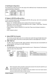
... describes the states of UMA Frame Buffer Size (refer to an external audio system that your device and then remove it from the motherboard. • When removing the cable, pull it side to side to 1 Gbps data rate. A. Do not rock it straight ...to a back panel connector, first remove the cable from your audio system provides an optical digital audio in connector. Dual Display Configurations: This motherboard provides three ports for more information) • Playback software: CyberLink PowerDVD 8.0 or later (Note: Please ensure Hardware Acceleration is occurring &#...
... describes the states of UMA Frame Buffer Size (refer to an external audio system that your device and then remove it from the motherboard. • When removing the cable, pull it side to side to 1 Gbps data rate. A. Do not rock it straight ...to a back panel connector, first remove the cable from your audio system provides an optical digital audio in connector. Dual Display Configurations: This motherboard provides three ports for more information) • Playback software: CyberLink PowerDVD 8.0 or later (Note: Please ensure Hardware Acceleration is occurring &#...
Manual
Page 24
... connectors you wish to connect. • Before installing the devices, be sure to the devices. • After installing the device and before turning on the motherboard. Hardware Installation - 24 - 1-9 Internal Connectors 13 5 2 8 12 6 21 13 20 4 14 15 16 9 18 1) ATX_12V_2X4 2) ATX 3) CPU_FAN 4) SYS_FAN1/SYS_FAN2 5) PWR_FAN 6) NB_FAN 7) FDD 8) IDE 9) SATA2_0/1/2/3/4/5 10...
... connectors you wish to connect. • Before installing the devices, be sure to the devices. • After installing the device and before turning on the motherboard. Hardware Installation - 24 - 1-9 Internal Connectors 13 5 2 8 12 6 21 13 20 4 14 15 16 9 18 1) ATX_12V_2X4 2) ATX 3) CPU_FAN 4) SYS_FAN1/SYS_FAN2 5) PWR_FAN 6) NB_FAN 7) FDD 8) IDE 9) SATA2_0/1/2/3/4/5 10...

Manual
Page 25
...providing a 2x4 12V and a 2x12 power connector, remove the protective covers from the 12V power connector and the main power connector on the motherboard. 1/2) ATX_12V_2X4/ATX (2x4 12V Power Connector and 2x12 Main Power Connector) With the use of the power connector, the power supply can... ATX_12V_2X4: Pin No. Before connecting the power connector, first make sure the power supply is turned off and all the components on the motherboard. The 12V power connector mainly supplies power to the power connector in the correct orientation. The power connector possesses a foolproof design.
...providing a 2x4 12V and a 2x12 power connector, remove the protective covers from the 12V power connector and the main power connector on the motherboard. 1/2) ATX_12V_2X4/ATX (2x4 12V Power Connector and 2x12 Main Power Connector) With the use of the power connector, the power supply can... ATX_12V_2X4: Pin No. Before connecting the power connector, first make sure the power supply is turned off and all the components on the motherboard. The 12V power connector mainly supplies power to the power connector in the correct orientation. The power connector possesses a foolproof design.
Manual
Page 26
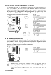
... a positive connection and requires a +12V voltage. Do not place a jumper cap on the headers. 3/4/5) CPU_FAN/SYS_FAN1/SYS_FAN2/PWR_FAN (Fan Headers) The motherboard has a 4-pin CPU fan header (CPU_FAN), a 3-pin (SYS_FAN2) and a 4-pin (SYS_ FAN1) system fan headers, and a 3-pin power ...12V / Speed Control 3 Sense 4 Reserve 1 1 SYS_FAN2 PWR_FAN SYS_FAN2/PWR_FAN: Pin No. Most fans are not configuration jumper blocks. Pin No. The motherboard supports CPU fan speed control, which requires the use of a CPU fan with color-coded power connector wires. Definition 1 CPU_FAN 1 GND 2 +12V...
... a positive connection and requires a +12V voltage. Do not place a jumper cap on the headers. 3/4/5) CPU_FAN/SYS_FAN1/SYS_FAN2/PWR_FAN (Fan Headers) The motherboard has a 4-pin CPU fan header (CPU_FAN), a 3-pin (SYS_FAN2) and a 4-pin (SYS_ FAN1) system fan headers, and a 3-pin power ...12V / Speed Control 3 Sense 4 Reserve 1 1 SYS_FAN2 PWR_FAN SYS_FAN2/PWR_FAN: Pin No. Most fans are not configuration jumper blocks. Pin No. The motherboard supports CPU fan speed control, which requires the use of a CPU fan with color-coded power connector wires. Definition 1 CPU_FAN 1 GND 2 +12V...
Manual
Page 30
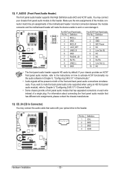
... information about connecting the front panel audio module that has separated connectors on both of a single plug. Incorrect connection between the module connector and the motherboard header will be present on each wire instead of the front and back panel audio connections simultaneously. 12) F_AUDIO (Front Panel Audio Header) The front... supports Intel High Definition audio (HD) and AC'97 audio. Make sure the wire assignments of the module connector match the pin assignments of the motherboard header.
... information about connecting the front panel audio module that has separated connectors on both of a single plug. Incorrect connection between the module connector and the motherboard header will be present on each wire instead of the front and back panel audio connections simultaneously. 12) F_AUDIO (Front Panel Audio Header) The front... supports Intel High Definition audio (HD) and AC'97 audio. Make sure the wire assignments of the module connector match the pin assignments of the motherboard header.


