Manual
Page 3
...be reproduced, copied, translated, transmitted, or published in this : "REV: X.X." Changes to the specifications and features in this product, GIGABYTE provides the following types of documentations: „ For quick set-up of the product, read the Quick Installation Guide included with the... before updating motherboard BIOS, drivers, or when looking for technical information. Documentation Classifications In order to their respective owners. All rights reserved. No part of GIGABYTE. For product-related information, check on our website at: http://www.gigabyte.com.tw Identifying ...
...be reproduced, copied, translated, transmitted, or published in this : "REV: X.X." Changes to the specifications and features in this product, GIGABYTE provides the following types of documentations: „ For quick set-up of the product, read the Quick Installation Guide included with the... before updating motherboard BIOS, drivers, or when looking for technical information. Documentation Classifications In order to their respective owners. All rights reserved. No part of GIGABYTE. For product-related information, check on our website at: http://www.gigabyte.com.tw Identifying ...
Manual
Page 4
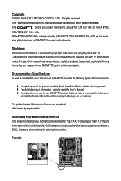
Table of Contents Box Contents ...6 OptionalItems ...6 GA-P31-S3G Motherboard Layout 7 Block Diagram ...8 Chapter 1 Hardware Installation 9 1-1 Installation Precautions 9 1-2 Product Specifications 10 1-3 Installing the CPU and CPU Cooler 13 ... Memory 17 1-5 Installing an Expansion Card 18 1-6 Back Panel Connectors 19 1-7 Internal Connectors 21 Chapter 2 BIOS Setup 31 2-1 Startup Screen 32 2-2 The Main Menu 33 2-3 Standard CMOS Features 35 2-4 Advanced BIOS Features 37 2-5 IntegratedPeripherals 39 2-6 Power Management Setup 42 2-7 PnP/PCI Configurations 44 2-8 PC Health Status ...
Table of Contents Box Contents ...6 OptionalItems ...6 GA-P31-S3G Motherboard Layout 7 Block Diagram ...8 Chapter 1 Hardware Installation 9 1-1 Installation Precautions 9 1-2 Product Specifications 10 1-3 Installing the CPU and CPU Cooler 13 ... Memory 17 1-5 Installing an Expansion Card 18 1-6 Back Panel Connectors 19 1-7 Internal Connectors 21 Chapter 2 BIOS Setup 31 2-1 Startup Screen 32 2-2 The Main Menu 33 2-3 Standard CMOS Features 35 2-4 Advanced BIOS Features 37 2-5 IntegratedPeripherals 39 2-6 Power Management Setup 42 2-7 PnP/PCI Configurations 44 2-8 PC Health Status ...
Manual
Page 5
... 54 3-3 Driver CD Information 54 3-4 Hardware Information 55 3-5 Contact Us ...55 Chapter 4 Unique Features 57 4-1 Xpress Recovery2 57 4-2 BIOS Update Utilities 62 4-2-1 Updating the BIOS with the Q-Flash Utility 62 4-2-2 Updating the BIOS with the @BIOS Utility 65 4-3 EasyTune 5 Pro 67 4-4 Windows Vista ReadyBoost 68 Chapter 5 Appendix ...69 5-1 ConfiguringAudio Input and Output 69 5-1-1 Configuring...
... 54 3-3 Driver CD Information 54 3-4 Hardware Information 55 3-5 Contact Us ...55 Chapter 4 Unique Features 57 4-1 Xpress Recovery2 57 4-2 BIOS Update Utilities 62 4-2-1 Updating the BIOS with the Q-Flash Utility 62 4-2-2 Updating the BIOS with the @BIOS Utility 65 4-3 EasyTune 5 Pro 67 4-4 Windows Vista ReadyBoost 68 Chapter 5 Appendix ...69 5-1 ConfiguringAudio Input and Output 69 5-1-1 Configuring...
Manual
Page 8
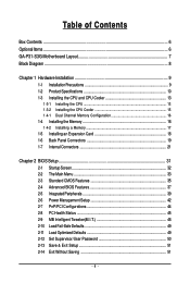
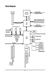
Block Diagram PCIe CLK (100 MHz) LGA775 Processor Host Interface PCI Express x16 Intel® P31 3 PCI Express x1 CPU CLK+/(333/266/200 MHz) DDR2 1066/800/667 MHz Dual Channel Memory MCH CLK (333/266/200 MHz) PCIe CLK (100 MHz) x1 x1 x1 PCI Express Bus RTL8111B RJ45 LAN PCI Bus Intel® ICH7 CODEC BIOS ATA-100/66/33 IDE Channel 4 SATA 3Gb/s 8 USB Ports IT8718 Floppy LPT Port COM Port PS/2 KB/Mouse MIC (Center/Subwoofer Speaker Out) Line-Out (Front Speaker Out) Line-In (Rear Speaker Out) SPDIF Out 3 PCI PCI CLK (33 MHz) - 8 -
Block Diagram PCIe CLK (100 MHz) LGA775 Processor Host Interface PCI Express x16 Intel® P31 3 PCI Express x1 CPU CLK+/(333/266/200 MHz) DDR2 1066/800/667 MHz Dual Channel Memory MCH CLK (333/266/200 MHz) PCIe CLK (100 MHz) x1 x1 x1 PCI Express Bus RTL8111B RJ45 LAN PCI Bus Intel® ICH7 CODEC BIOS ATA-100/66/33 IDE Channel 4 SATA 3Gb/s 8 USB Ports IT8718 Floppy LPT Port COM Port PS/2 KB/Mouse MIC (Center/Subwoofer Speaker Out) Line-Out (Front Speaker Out) Line-In (Rear Speaker Out) SPDIF Out 3 PCI PCI CLK (33 MHz) - 8 -
Manual
Page 11
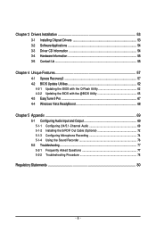
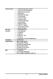
... Š CPU temperature detection Š CPU/System fan speed detection Š CPU overheating warning Š CPU/System fan fail warning Š CPU fan speed control BIOS Š 1 x 4 Mbit flash Š Use of licensed AWARD BIOS Š PnP 1.0a, DMI 2.0, SM BIOS 2.3, ACPI 1.0b - 11 - Hardware Installation
... Š CPU temperature detection Š CPU/System fan speed detection Š CPU overheating warning Š CPU/System fan fail warning Š CPU fan speed control BIOS Š 1 x 4 Mbit flash Š Use of licensed AWARD BIOS Š PnP 1.0a, DMI 2.0, SM BIOS 2.3, ACPI 1.0b - 11 - Hardware Installation
Manual
Page 12
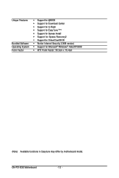
GA-P31-S3G Motherboard - 12 - Unique Features Bundled Software Operating System Form Factor Š Support for @BIOS Š Support for Download Center Š Support for Q-Flash Š Support for EasyTune (Note) Š Support for Xpress Install Š Support for Xpress Recovery2 Š Support for Virtual Dual BIOS Š Norton Internet Security (OEM version) Š Support for Microsoft® Windows® Vista/XP/2000 Š ATX Form Factor; 30.5cm x 19.4cm (Note) Available functions in Easytune may differ by motherboard model.
GA-P31-S3G Motherboard - 12 - Unique Features Bundled Software Operating System Form Factor Š Support for @BIOS Š Support for Download Center Š Support for Q-Flash Š Support for EasyTune (Note) Š Support for Xpress Install Š Support for Xpress Recovery2 Š Support for Virtual Dual BIOS Š Norton Internet Security (OEM version) Š Support for Microsoft® Windows® Vista/XP/2000 Š ATX Form Factor; 30.5cm x 19.4cm (Note) Available functions in Easytune may differ by motherboard model.
Manual
Page 16
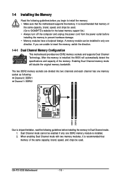
... only one direction. When enabling Dual Channel mode with two memory modules, it is installed, the BIOS will double the original memory bandwidth. GA-P31-S3G Motherboard - 16 - It is installed. 2. A memory module can be used . (Go to GIGABYTE's website for the latest memory support list.) • Always turn off the computer and unplug the...
... only one direction. When enabling Dual Channel mode with two memory modules, it is installed, the BIOS will double the original memory bandwidth. GA-P31-S3G Motherboard - 16 - It is installed. 2. A memory module can be used . (Go to GIGABYTE's website for the latest memory support list.) • Always turn off the computer and unplug the...

Manual
Page 18
... expansion card in the expansion slot. 1. After installing all expansion cards, replace the chassis cover(s). 6. If necessary, go to BIOS Setup to make any required BIOS changes for your computer. Secure the card's metal bracket to the chassis back panel with the slot, and press down on your...Express x16 Slot PCI Slot Follow the steps below to correctly install your expansion card in your card. Align the card with a screw. 5. GA-P31-S3G Motherboard - 18 - Carefully read the manual that supports your operating system. Make sure the card is fully seated in the slot and does ...
... expansion card in the expansion slot. 1. After installing all expansion cards, replace the chassis cover(s). 6. If necessary, go to BIOS Setup to make any required BIOS changes for your computer. Secure the card's metal bracket to the chassis back panel with the slot, and press down on your...Express x16 Slot PCI Slot Follow the steps below to correctly install your expansion card in your card. Align the card with a screw. 5. GA-P31-S3G Motherboard - 18 - Carefully read the manual that supports your operating system. Make sure the card is fully seated in the slot and does ...
Manual
Page 26
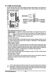
.../ Power/ Sleep LED SPEAK- 20 19 SPEAK+ PWPW+ MSGMSG+ 21 NC RES+ RESHD- The LED is off when the system is detected, the BIOS may differ by issuing a beep code. If a problem is in S3/S4/S5 Off S3/S4 sleep state or powered off your chassis front panel... or writing data. • RES (Reset Switch, Green): Connects to the power switch on the chassis front panel. GA-P31-S3G Motherboard - 26 - When connecting your system using the power switch (refer to Chapter 2, "BIOS Setup," "Power Management Setup," for information about beep codes. • HD (IDE Hard Drive Activity LED, Blue)...
.../ Power/ Sleep LED SPEAK- 20 19 SPEAK+ PWPW+ MSGMSG+ 21 NC RES+ RESHD- The LED is off when the system is detected, the BIOS may differ by issuing a beep code. If a problem is in S3/S4/S5 Off S3/S4 sleep state or powered off your chassis front panel... or writing data. • RES (Reset Switch, Green): Connects to the power switch on the chassis front panel. GA-P31-S3G Motherboard - 26 - When connecting your system using the power switch (refer to Chapter 2, "BIOS Setup," "Power Management Setup," for information about beep codes. • HD (IDE Hard Drive Activity LED, Blue)...
Manual
Page 28
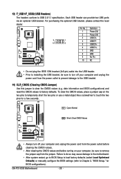
...) and reset the CMOS values to touch the two pins for BIOS configurations). To clear the CMOS values, place a jumper cap on your computer, be sure to turn off your computer and unplug the power cord from the jumper. GA-P31-S3G Motherboard - 28 - Each USB header can provide two USB ports... via an optional USB bracket. Failure to do so may cause damage to the motherboard. • After system restart, go to BIOS Setup to load factory defaults (select Load Optimized ...
...) and reset the CMOS values to touch the two pins for BIOS configurations). To clear the CMOS values, place a jumper cap on your computer, be sure to turn off your computer and unplug the power cord from the jumper. GA-P31-S3G Motherboard - 28 - Each USB header can provide two USB ports... via an optional USB bracket. Failure to do so may cause damage to the motherboard. • After system restart, go to BIOS Setup to load factory defaults (select Load Optimized ...
Manual
Page 29
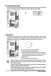
... a screwdriver to replace the battery by removing the battery: 1. Definition 1 Signal 1 2 GND 16) BAT (Battery) The battery provides power to keep the values (such as BIOS configurations, date, and time information) in the CMOS when the computer is replaced with an incorrect model. • Contact the place of purchase or local...
... a screwdriver to replace the battery by removing the battery: 1. Definition 1 Signal 1 2 GND 16) BAT (Battery) The battery provides power to keep the values (such as BIOS configurations, date, and time information) in the CMOS when the computer is replaced with an incorrect model. • Contact the place of purchase or local...
Manual
Page 31
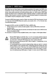
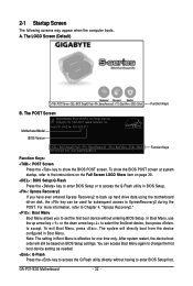
...in the CMOS. To flash the BIOS, do not encounter problems using the current version of BIOS, it with caution. Its major functions include conducting the Power-On Self-Test (POST) during the POST. To upgrade the BIOS, use either the GIGABYTE Q-Flash or @BIOS utility. • Q-Flash allows ...the user to quickly and easily upgrade or back up BIOS without entering the operating system. • @BIOS is turned off, the battery on the motherboard supplies the ...
...in the CMOS. To flash the BIOS, do not encounter problems using the current version of BIOS, it with caution. Its major functions include conducting the Power-On Self-Test (POST) during the POST. To upgrade the BIOS, use either the GIGABYTE Q-Flash or @BIOS utility. • Q-Flash allows ...the user to quickly and easily upgrade or back up BIOS without entering the operating system. • @BIOS is turned off, the battery on the motherboard supplies the ...
Manual
Page 32
...boot device setting as needed. : Q-Flash Press the key to access the Q-Flash utility directly without entering BIOS Setup. GA-P31-S3G Motherboard - 32 - Motherboard Model BIOS Version Intel P31 BIOS for one time only. For more information, refer to Chapter 4, "Xpress Recovery2." : Boot Menu Boot Menu...device boot order will directly boot from the device configured in Boot Menu is effective for P31-S3G E11 . . . . : BIOS Setup/Q-Flash : XpressRecovery2 : Boot Menu : Qflash 09/12/2007-P31-ICH7-6A89OG08C-00 Function Keys Function Keys: : POST Screen Press the key to show the...
...boot device setting as needed. : Q-Flash Press the key to access the Q-Flash utility directly without entering BIOS Setup. GA-P31-S3G Motherboard - 32 - Motherboard Model BIOS Version Intel P31 BIOS for one time only. For more information, refer to Chapter 4, "Xpress Recovery2." : Boot Menu Boot Menu...device boot order will directly boot from the device configured in Boot Menu is effective for P31-S3G E11 . . . . : BIOS Setup/Q-Flash : XpressRecovery2 : Boot Menu : Qflash 09/12/2007-P31-ICH7-6A89OG08C-00 Function Keys Function Keys: : POST Screen Press the key to show the...
Manual
Page 33
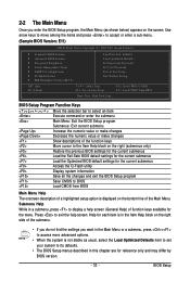
... Set User Password Save & Exit Setup Exit Without Saving ESC: Quit F8: Q-Flash KLJI: Select Item F10: Save & Exit Setup F11: Save CMOS to BIOS F12: Load CMOS from BIOS Main Menu Help The onscreen description of a highlighted setup option is not stable as shown below) appears on the screen. Press to... BIOS Load CMOS from BIOS Time, Date, Hard Disk Type... Help for each item is in the Item Help block on the right side of the submenu. • If you ...
... Set User Password Save & Exit Setup Exit Without Saving ESC: Quit F8: Q-Flash KLJI: Select Item F10: Save & Exit Setup F11: Save CMOS to BIOS F12: Load CMOS from BIOS Main Menu Help The onscreen description of a highlighted setup option is not stable as shown below) appears on the screen. Press to... BIOS Load CMOS from BIOS Time, Date, Hard Disk Type... Help for each item is in the Item Help block on the right side of the submenu. • If you ...
Manual
Page 34
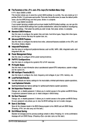
..., integrated audio, and integrated LAN, etc. „ Power Management Setup Use this menu to configure all changes and the previous settings remain in BIOS Setup. „ Set User Password Change, set , or disable password. You can also carry out this function to make changes in effect. ... keys (For the Main Menu Only) ` F11: Save CMOS to BIOS This function allows you to restrict access to erase the default profile name, use this task.) GA-P31-S3G Motherboard - 34 - It allows you to save the current BIOS settings to 8 profiles (Profile 1-8) and name each profile. Pressing to...
..., integrated audio, and integrated LAN, etc. „ Power Management Setup Use this menu to configure all changes and the previous settings remain in BIOS Setup. „ Set User Password Change, set , or disable password. You can also carry out this function to make changes in effect. ... keys (For the Main Menu Only) ` F11: Save CMOS to BIOS This function allows you to restrict access to erase the default profile name, use this task.) GA-P31-S3G Motherboard - 34 - It allows you to save the current BIOS settings to 8 profiles (Profile 1-8) and name each profile. Pressing to...
Manual
Page 35
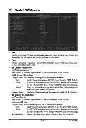
... - Select the desired field and use the up arrow or down arrow key to set the date. is week (read-only), month, date and year. BIOS Setup Select the desired field and use the up arrow or down arrow key to set the time. Allows you to manually enter the specifications... this item to CHS. Extended IDE Drive Configure your IDE/SATA devices by using one of the two methods below: • Auto • None Lets BIOS automatically detect IDE/SATA devices during the POST. (Default) If no IDE/SATA devices are used, set this item to None so the system will...
... - Select the desired field and use the up arrow or down arrow key to set the date. is week (read-only), month, date and year. BIOS Setup Select the desired field and use the up arrow or down arrow key to set the time. Allows you to manually enter the specifications... this item to CHS. Extended IDE Drive Configure your IDE/SATA devices by using one of the two methods below: • Auto • None Lets BIOS automatically detect IDE/SATA devices during the POST. (Default) If no IDE/SATA devices are used, set this item to None so the system will...
Manual
Page 36
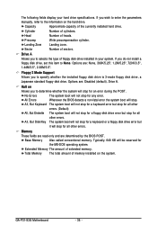
... extended memory. Base Memory Also called conventional memory. Capacity Approximate capacity of heads. Options are determined by the BIOS POST. All Errors Whenever the BIOS detects a non-fatal error the system boot will stop for all other errors. All, But Keyboard The system...44M/3.5", 2.88M/3.5". Total Memory The total amount of cylinders. Halt on Allows you wish to enter the parameters manually, refer to None. GA-P31-S3G Motherboard - 36 - If you to specify whether the installed floppy disk drive is 3-mode floppy disk drive, a Japanese standard floppy disk...
... extended memory. Base Memory Also called conventional memory. Capacity Approximate capacity of heads. Options are determined by the BIOS POST. All Errors Whenever the BIOS detects a non-fatal error the system boot will stop for all other errors. All, But Keyboard The system...44M/3.5", 2.88M/3.5". Total Memory The total amount of cylinders. Halt on Allows you wish to enter the parameters manually, refer to None. GA-P31-S3G Motherboard - 36 - If you to specify whether the installed floppy disk drive is 3-mode floppy disk drive, a Japanese standard floppy disk...

Manual
Page 37
..., CDROM, ZIP, USB-FDD, USB-ZIP, USB-CDROM, USB-HDD, LAN, Disabled. Setup A password is only required for entering the BIOS Setup program. HDD S.M.A.R.T. This feature allows your hard drive. First/Second/Third Boot Device Specifies the boot order from the installed hard drives. ...For more information about Intel CPUs' unique features, please visit Intel's website. - 37 - BIOS Setup Press to 3 (Note) No-Execute Memory Protect (Note) CPU Enhanced Halt (C1E) (Note) CPU Thermal Monitor 2(TM2) (Note) CPU EIST...
..., CDROM, ZIP, USB-FDD, USB-ZIP, USB-CDROM, USB-HDD, LAN, Disabled. Setup A password is only required for entering the BIOS Setup program. HDD S.M.A.R.T. This feature allows your hard drive. First/Second/Third Boot Device Specifies the boot order from the installed hard drives. ...For more information about Intel CPUs' unique features, please visit Intel's website. - 37 - BIOS Setup Press to 3 (Note) No-Execute Memory Protect (Note) CPU Enhanced Halt (C1E) (Note) CPU Thermal Monitor 2(TM2) (Note) CPU EIST...
Manual
Page 39
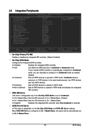
... only if the On-Chip SATA Mode is selected. PATA IDE Set to operate in PATA mode and disables the integrated IDE controller. Auto Lets BIOS set SATA devices to Ch. 1 Master/Slave. Sets all SATA devices to Ch. 0 Master/Slave. - 39 - Disabled Disables the integrated ... Peripherals On-Chip Primary PCI IDE On-Chip SATA Mode x PATA IDE Set to SATA Port 0/2 Set to SATA Port 1/3 Set to Combined. BIOS Setup Disabled Disables the integrated SATA controller. Combined allows a maximum of 4 ATA devices to be automatically set to USB Controller USB 2.0 Controller USB...
... only if the On-Chip SATA Mode is selected. PATA IDE Set to operate in PATA mode and disables the integrated IDE controller. Auto Lets BIOS set SATA devices to Ch. 1 Master/Slave. Sets all SATA devices to Ch. 0 Master/Slave. - 39 - Disabled Disables the integrated ... Peripherals On-Chip Primary PCI IDE On-Chip SATA Mode x PATA IDE Set to SATA Port 0/2 Set to SATA Port 1/3 Set to Combined. BIOS Setup Disabled Disables the integrated SATA controller. Combined allows a maximum of 4 ATA devices to be automatically set to USB Controller USB 2.0 Controller USB...
Manual
Page 41
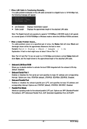
... onboard parallel port (LPT) and specifies its base I /O address and corresponding interrupt. Parallel Port Mode Selects an operating mode for the onboard parallel (LPT) port. BIOS Setup Note: The Gigabit hub will show Open, and the length shown is activated. Options are not used in MS-DOS mode; When LAN Cable...
... onboard parallel port (LPT) and specifies its base I /O address and corresponding interrupt. Parallel Port Mode Selects an operating mode for the onboard parallel (LPT) port. BIOS Setup Note: The Gigabit hub will show Open, and the length shown is activated. Options are not used in MS-DOS mode; When LAN Cable...


