Manual
Page 4
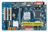
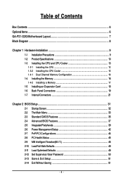
Table of Contents Box Contents ...6 OptionalItems ...6 GA-P31-S3G Motherboard Layout 7 Block Diagram ...8 Chapter 1 Hardware Installation 9 1-1 Installation Precautions 9 1-2 Product Specifications 10 1-3 Installing the CPU and CPU Cooler 13 1-3-1 Installing the CPU 13 1-3-2 Installing the CPU Cooler 15 1-4-1 Dual Channel Memory Configuration 16 1-4 Installing the Memory 16 1-4-2 Installing a Memory 17 1-5 Installing an Expansion Card 18 1-6 Back Panel Connectors 19...
Table of Contents Box Contents ...6 OptionalItems ...6 GA-P31-S3G Motherboard Layout 7 Block Diagram ...8 Chapter 1 Hardware Installation 9 1-1 Installation Precautions 9 1-2 Product Specifications 10 1-3 Installing the CPU and CPU Cooler 13 1-3-1 Installing the CPU 13 1-3-2 Installing the CPU Cooler 15 1-4-1 Dual Channel Memory Configuration 16 1-4 Installing the Memory 16 1-4-2 Installing a Memory 17 1-5 Installing an Expansion Card 18 1-6 Back Panel Connectors 19...
Manual
Page 8
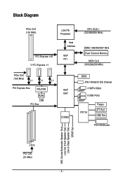
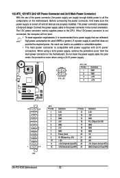
Block Diagram PCIe CLK (100 MHz) LGA775 Processor Host Interface PCI Express x16 Intel® P31 3 PCI Express x1 CPU CLK+/(333/266/200 MHz) DDR2 1066/800/667 MHz Dual Channel Memory MCH CLK (333/266/200 MHz) PCIe CLK (100 MHz) x1 x1 x1 PCI Express Bus RTL8111B RJ45 LAN PCI Bus Intel® ICH7 CODEC BIOS ATA-100/66/33 IDE Channel 4 SATA 3Gb/s 8 USB Ports IT8718 Floppy LPT Port COM Port PS/2 KB/Mouse MIC (Center/Subwoofer Speaker Out) Line-Out (Front Speaker Out) Line-In (Rear Speaker Out) SPDIF Out 3 PCI PCI CLK (33 MHz) - 8 -
Block Diagram PCIe CLK (100 MHz) LGA775 Processor Host Interface PCI Express x16 Intel® P31 3 PCI Express x1 CPU CLK+/(333/266/200 MHz) DDR2 1066/800/667 MHz Dual Channel Memory MCH CLK (333/266/200 MHz) PCIe CLK (100 MHz) x1 x1 x1 PCI Express Bus RTL8111B RJ45 LAN PCI Bus Intel® ICH7 CODEC BIOS ATA-100/66/33 IDE Channel 4 SATA 3Gb/s 8 USB Ports IT8718 Floppy LPT Port COM Port PS/2 KB/Mouse MIC (Center/Subwoofer Speaker Out) Line-Out (Front Speaker Out) Line-In (Rear Speaker Out) SPDIF Out 3 PCI PCI CLK (33 MHz) - 8 -
Manual
Page 9
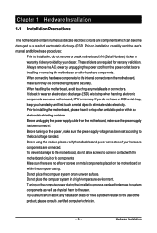
.... • Prior to installing the motherboard, please have a problem related to wear an electrostatic discharge (ESD) wrist strap when handling electronic components such as a motherboard, CPU or memory.
.... • Prior to installing the motherboard, please have a problem related to wear an electrostatic discharge (ESD) wrist strap when handling electronic components such as a motherboard, CPU or memory.
Manual
Page 10
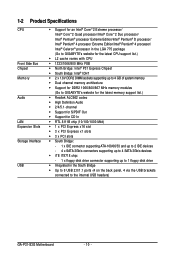
...® 4 processor/ Intel® Celeron® processor in the LGA 775 package (Go to GIGABYTE's website for the latest CPU support list.) Š L2 cache varies with CPU Š 1333/1066/800 MHz FSB Š North Bridge: Intel® P31 Express Chipset Š South Bridge: Intel® ICH7 Š 2 x 1.8V DDR2 DIMM sockets supporting... Š Integrated in the South Bridge Š Up to 8 USB 2.0/1.1 ports (4 on the back panel, 4 via the USB brackets connected to the internal USB headers) GA-P31-S3G Motherboard - 10 -
...® 4 processor/ Intel® Celeron® processor in the LGA 775 package (Go to GIGABYTE's website for the latest CPU support list.) Š L2 cache varies with CPU Š 1333/1066/800 MHz FSB Š North Bridge: Intel® P31 Express Chipset Š South Bridge: Intel® ICH7 Š 2 x 1.8V DDR2 DIMM sockets supporting... Š Integrated in the South Bridge Š Up to 8 USB 2.0/1.1 ports (4 on the back panel, 4 via the USB brackets connected to the internal USB headers) GA-P31-S3G Motherboard - 10 -
Manual
Page 11
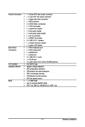
...Š 1 x 4-pin ATX 12V power connector Š 1 x floppy disk drive connector Š 1 x IDE connector Š 4 x SATA 3Gb/s connectors Š 1 x CPU fan header Š 1 x system fan header Š 1 x front panel header Š 1 x front panel audio header Š 1 x CD In connector Š 1 x... Š iTE IT8718 chip Hardware Monitor Š System voltage detection Š CPU temperature detection Š CPU/System fan speed detection Š CPU overheating warning Š CPU/System fan fail warning Š CPU fan speed control BIOS Š 1 x 4 Mbit flash Š Use ...
...Š 1 x 4-pin ATX 12V power connector Š 1 x floppy disk drive connector Š 1 x IDE connector Š 4 x SATA 3Gb/s connectors Š 1 x CPU fan header Š 1 x system fan header Š 1 x front panel header Š 1 x front panel audio header Š 1 x CD In connector Š 1 x... Š iTE IT8718 chip Hardware Monitor Š System voltage detection Š CPU temperature detection Š CPU/System fan speed detection Š CPU overheating warning Š CPU/System fan fail warning Š CPU fan speed control BIOS Š 1 x 4 Mbit flash Š Use ...
Manual
Page 13
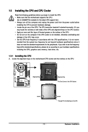
... Alignment Key LGA 775 CPU Alignment Key Pin One Corner of the CPU. 1-3 Installing the CPU and CPU Cooler Read the following guidelines before installing the CPU to your hardware specifications including the CPU, graphics card, memory, hard drive, etc. 1-3-1 Installing the CPU A. mended that the motherboard supports the CPU. (Go to GIGABYTE's website for the peripherals. Hardware Installation...
... Alignment Key LGA 775 CPU Alignment Key Pin One Corner of the CPU. 1-3 Installing the CPU and CPU Cooler Read the following guidelines before installing the CPU to your hardware specifications including the CPU, graphics card, memory, hard drive, etc. 1-3-1 Installing the CPU A. mended that the motherboard supports the CPU. (Go to GIGABYTE's website for the peripherals. Hardware Installation...
Manual
Page 14
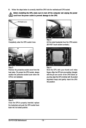
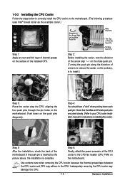
... plate and push the CPU socket lever back into its locked position. Before installing the CPU, make sure to correctly install the CPU into position. GA-P31-S3G Motherboard - 14 - Step 5: Once the CPU is not installed.) Step 4: Hold the CPU with the socket alignment keys) and gently insert the CPU into the motherboard CPU socket. CPU Socket Lever Step 1: Completely...
... plate and push the CPU socket lever back into its locked position. Before installing the CPU, make sure to correctly install the CPU into position. GA-P31-S3G Motherboard - 14 - Step 5: Once the CPU is not installed.) Step 4: Hold the CPU with the socket alignment keys) and gently insert the CPU into the motherboard CPU socket. CPU Socket Lever Step 1: Completely...
Manual
Page 15
...direction of the arrow sign on the male push pin. (Turning the push pin along the direction of the CPU cooler to install.) Step 3: Place the cooler atop the CPU, aligning the four push pins through the pin holes on the motherboard. Push down each push pin. Step ...Female push pins are joined closely. (Refer to the CPU. Use extreme care when removing the CPU cooler because the thermal grease/tape between the CPU cooler and CPU may damage the CPU. - 15 - Inadequately removing the CPU cooler may adhere to your CPU cooler installation manual for instructions on installing the cooler.)...
...direction of the arrow sign on the male push pin. (Turning the push pin along the direction of the CPU cooler to install.) Step 3: Place the cooler atop the CPU, aligning the four push pins through the pin holes on the motherboard. Push down each push pin. Step ...Female push pins are joined closely. (Refer to the CPU. Use extreme care when removing the CPU cooler because the thermal grease/tape between the CPU cooler and CPU may damage the CPU. - 15 - Inadequately removing the CPU cooler may adhere to your CPU cooler installation manual for instructions on installing the cooler.)...
Manual
Page 22
Connect the power supply cable to the CPU. Do not insert the power supply cable into pins under the protective cover when using a 2x12 power supply, remove the protective cover from the main ... 3.3V -12V GND PS_ON(soft On/Off) GND GND GND -5V +5V +5V +5V (Only for 2x12-pin ATX) GND (Only for 2x12-pin ATX) GA-P31-S3G Motherboard - 22 - Before connecting the power connector, first make sure the power supply is compatible with power supplies with 2x10 power connectors. If the 12V...
Connect the power supply cable to the CPU. Do not insert the power supply cable into pins under the protective cover when using a 2x12 power supply, remove the protective cover from the main ... 3.3V -12V GND PS_ON(soft On/Off) GND GND GND -5V +5V +5V +5V (Only for 2x12-pin ATX) GND (Only for 2x12-pin ATX) GA-P31-S3G Motherboard - 22 - Before connecting the power connector, first make sure the power supply is compatible with power supplies with 2x10 power connectors. If the 12V...

Manual
Page 23
.../ Speed Control Sense Speed Control Definition GND +12V Sense • Be sure to connect fan cables to the fan headers to the CPU or the system may hang. • These fan headers are not configuration jumper blocks. The types of floppy disk drives supported are ...2 - 23 - A red power connector wire indicates a positive connection and requires a +12V voltage. 3/4) CPU_FAN/SYS_FAN (Fan Headers) The motherboard has a 4-pin CPU fan header (CPU_FAN) and a 3-pin system fan header (SYS_FAN). Each fan header supplies a +12V power voltage and possesses a foolproof insertion design. Most fans are...
.../ Speed Control Sense Speed Control Definition GND +12V Sense • Be sure to connect fan cables to the fan headers to the CPU or the system may hang. • These fan headers are not configuration jumper blocks. The types of floppy disk drives supported are ...2 - 23 - A red power connector wire indicates a positive connection and requires a +12V voltage. 3/4) CPU_FAN/SYS_FAN (Fan Headers) The motherboard has a 4-pin CPU fan header (CPU_FAN) and a 3-pin system fan header (SYS_FAN). Each fan header supplies a +12V power voltage and possesses a foolproof insertion design. Most fans are...
Manual
Page 34
... Power Management Setup Use this menu to configure all changes and the previous settings remain in effect. You can also carry out this task.) GA-P31-S3G Motherboard - 34 - First enter the profile name (to erase the default profile name, use this function to load the BIOS settings from BIOS...Use this menu to configure the system's PCI & PnP resources. „ PC Health Status Use this menu to see information about autodetected system/CPU temperature, system voltage and fan speed, etc. „ MB Intelligent Tweaker(M.I.T.) Use this menu to configure the clock, frequency and voltages of ...
... Power Management Setup Use this menu to configure all changes and the previous settings remain in effect. You can also carry out this task.) GA-P31-S3G Motherboard - 34 - First enter the profile name (to erase the default profile name, use this function to load the BIOS settings from BIOS...Use this menu to configure the system's PCI & PnP resources. „ PC Health Status Use this menu to see information about autodetected system/CPU temperature, system voltage and fan speed, etc. „ MB Intelligent Tweaker(M.I.T.) Use this menu to configure the clock, frequency and voltages of ...

Manual
Page 37
... only required for entering the BIOS Setup program. (Default) System A password is required every time the system boots, or only when you install a CPU that supports this feature. This feature allows your hard drive. Use the up or down arrow key to select a hard drive, then press the plus... (or ) to move it up or down on the list. First/Second/Third Boot Device Specifies the boot order from the installed hard drives. Capability CPU Multi-Threading (Note) Limit CPUID Max. HDD S.M.A.R.T. to accept. Options are: Floppy, LS120, Hard Disk, CDROM, ZIP, USB-FDD, USB-ZIP, USB-...
... only required for entering the BIOS Setup program. (Default) System A password is required every time the system boots, or only when you install a CPU that supports this feature. This feature allows your hard drive. Use the up or down arrow key to select a hard drive, then press the plus... (or ) to move it up or down on the list. First/Second/Third Boot Device Specifies the boot order from the installed hard drives. Capability CPU Multi-Threading (Note) Limit CPUID Max. HDD S.M.A.R.T. to accept. Options are: Floppy, LS120, Hard Disk, CDROM, ZIP, USB-FDD, USB-ZIP, USB-...

Manual
Page 38
... Screen LOGO Show Allows you to determine whether to display the GIGABYTE Logo at system startup. GA-P31-S3G Motherboard - 38 - to 3 (Note) Allows you install a CPU that supports this feature. When enabled, the CPU core frequency and voltage will be reduced when the CPU is present only if you to determine whether to limit CPUID maximum...
... Screen LOGO Show Allows you to determine whether to display the GIGABYTE Logo at system startup. GA-P31-S3G Motherboard - 38 - to 3 (Note) Allows you install a CPU that supports this feature. When enabled, the CPU core frequency and voltage will be reduced when the CPU is present only if you to determine whether to limit CPUID maximum...
Manual
Page 45
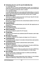
... connection when this field will show "Yes", otherwise it will emit warning sound. Current CPU Temperature Displays current CPU temperature. CPU Warning Temperature Sets the warning threshold for CPU temperature. Enabled allows the CPU fan to run at full speed. (Default: Enabled) - 45 - 2-8 PC Health...Health Status Reset Case Open Status Case Opened Vcore DDR18V +3.3V +12V Current CPU Temperature Current CPU FAN Speed Current SYSTEM FAN Speed CPU Warning Temperature CPU FAN Fail Warning SYSTEM FAN Fail Warning CPU Smart FAN Control [Disabled] No 1.438V 1.840V 3.344V 12.112V 47oC ...
... connection when this field will show "Yes", otherwise it will emit warning sound. Current CPU Temperature Displays current CPU temperature. CPU Warning Temperature Sets the warning threshold for CPU temperature. Enabled allows the CPU fan to run at full speed. (Default: Enabled) - 45 - 2-8 PC Health...Health Status Reset Case Open Status Case Opened Vcore DDR18V +3.3V +12V Current CPU Temperature Current CPU FAN Speed Current SYSTEM FAN Speed CPU Warning Temperature CPU FAN Fail Warning SYSTEM FAN Fail Warning CPU Smart FAN Control [Disabled] No 1.438V 1.840V 3.344V 12.112V 47oC ...

Manual
Page 46
...other unexpected results. (Inadequately altering the settings may result in damage to alter the clock ratio for the installed CPU. GA-P31-S3G Motherboard - 46 - Robust Graphics Booster Robust Graphics Booster (R.G.B.) helps to optimize the system voltage settings. Auto ...MB Intelligent Tweaker(M.I.T.) CMOS Setup Utility-Copyright (C) 1984-2007 Award Software MB Intelligent Tweaker(M.I.T.) Robust Graphics Booster CPU Clock Ratio (Note) CPU Host Clock Control x CPU Host Frequency (Mhz) PCI Express Frequency (Mhz) Performance Enhance System Memory Multiplier (SPD) Memory Frequency (...
...other unexpected results. (Inadequately altering the settings may result in damage to alter the clock ratio for the installed CPU. GA-P31-S3G Motherboard - 46 - Robust Graphics Booster Robust Graphics Booster (R.G.B.) helps to optimize the system voltage settings. Auto ...MB Intelligent Tweaker(M.I.T.) CMOS Setup Utility-Copyright (C) 1984-2007 Award Software MB Intelligent Tweaker(M.I.T.) Robust Graphics Booster CPU Clock Ratio (Note) CPU Host Clock Control x CPU Host Frequency (Mhz) PCI Express Frequency (Mhz) Performance Enhance System Memory Multiplier (SPD) Memory Frequency (...
Manual
Page 47
... allows all voltage control items below to be set memory voltage. Note: Increasing memory voltage may result in accordance with the CPU specifications. System Voltage Control Determines whether to manually set this item to 150 MHz. Normal Supplies the FSB voltage as required...its good performance level. (Default) Extreme Lets the system operate at three different performance levels. This item is configurable only if the CPU Host Clock Control option is the normal operating frequency of the memory being used; Normal Supplies the PCIe bus voltage as required. (...
... allows all voltage control items below to be set memory voltage. Note: Increasing memory voltage may result in accordance with the CPU specifications. System Voltage Control Determines whether to manually set this item to 150 MHz. Normal Supplies the FSB voltage as required...its good performance level. (Default) Extreme Lets the system operate at three different performance levels. This item is configurable only if the CPU Host Clock Control option is the normal operating frequency of the memory being used; Normal Supplies the PCIe bus voltage as required. (...
Manual
Page 48
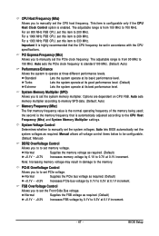
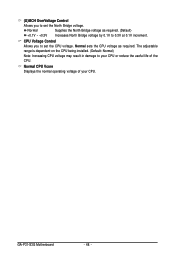
.... The adjustable range is dependent on the CPU being installed. (Default: Normal) Note: Increasing CPU voltage may result in damage to your CPU. Normal CPU Vcore Displays the normal operating voltage of your CPU or reduce the useful life of the CPU. CPU Voltage Control Allows you to set the CPU voltage. GA-P31-S3G Motherboard - 48 - (G)MCH OverVoltage Control Allows...
.... The adjustable range is dependent on the CPU being installed. (Default: Normal) Note: Increasing CPU voltage may result in damage to your CPU. Normal CPU Vcore Displays the normal operating voltage of your CPU or reduce the useful life of the CPU. CPU Voltage Control Allows you to set the CPU voltage. GA-P31-S3G Motherboard - 48 - (G)MCH OverVoltage Control Allows...

Manual
Page 67
...HEALTH setting page Confirmation/execution button Toggles among Easy Mode, Advanced Mode, and Graphics Mode Displays the CPU frequency Shows the supported function(s) Go to GIGABYTE website to update EasyTune 5 Pro Opens EasyTune 5 Pro help file Quits or minimizes the EasyTune 5...memory and reduce the useful life of these components. Unique Features Function LEDs 9. EASY MODE/ADVANCED MODE/ GRAPHICS 7. Help 11. may provide optimizations for CPU and memory, enhancing the performance of these components. - 67 - SMART FAN 4. PC HEALTH 5. and M.I .A. C.I.A./M.I .B. (Note 2), smart ...
...HEALTH setting page Confirmation/execution button Toggles among Easy Mode, Advanced Mode, and Graphics Mode Displays the CPU frequency Shows the supported function(s) Go to GIGABYTE website to update EasyTune 5 Pro Opens EasyTune 5 Pro help file Quits or minimizes the EasyTune 5...memory and reduce the useful life of these components. Unique Features Function LEDs 9. EASY MODE/ADVANCED MODE/ GRAPHICS 7. Help 11. may provide optimizations for CPU and memory, enhancing the performance of these components. - 67 - SMART FAN 4. PC HEALTH 5. and M.I .A. C.I.A./M.I .B. (Note 2), smart ...
Manual
Page 78
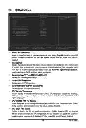
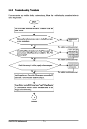
...the ATX main power cable and the 12V power cable. Connect the CPU cooler power cable to start the computer. START Turn off the power. No Correctly insert the memory into the memory socket. A (Continued...) GA-P31-S3G Motherboard - 78 - Remove all peripherals, connecting cables, and power... cord etc. Is the power connector of the CPU cooler connected to solve the problem. Yes Check if the memory is verified and ...
...the ATX main power cable and the 12V power cable. Connect the CPU cooler power cable to start the computer. START Turn off the power. No Correctly insert the memory into the memory socket. A (Continued...) GA-P31-S3G Motherboard - 78 - Remove all peripherals, connecting cables, and power... cord etc. Is the power connector of the CPU cooler connected to solve the problem. Yes Check if the memory is verified and ...
Manual
Page 79
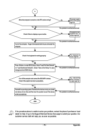
... device, connector, or cable might fail. The problem is verified and solved. The problem is verified and solved. No The power supply, CPU or CPU socket might fail. The problem is working properly. END If the procedure above is unable to see if the device works successfully). A When...the computer is turned on your monitor. Check if the keyboard is verified and solved. Yes Reinstall the operating system. The problem is the CPU cooler running? Reinstall other devices one by one (install one device at one time and then boot the system to solve your problem, contact...
... device, connector, or cable might fail. The problem is verified and solved. The problem is verified and solved. No The power supply, CPU or CPU socket might fail. The problem is working properly. END If the procedure above is unable to see if the device works successfully). A When...the computer is turned on your monitor. Check if the keyboard is verified and solved. Yes Reinstall the operating system. The problem is the CPU cooler running? Reinstall other devices one by one (install one device at one time and then boot the system to solve your problem, contact...


