Manual
Page 4
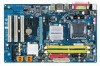
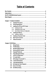
Table of Contents Box Contents ...6 OptionalItems ...6 GA-P31-S3G Motherboard Layout 7 Block Diagram ...8 Chapter 1 Hardware Installation 9 1-1 Installation Precautions 9 1-2 Product Specifications 10 1-3 Installing the CPU and CPU Cooler 13 1-3-1 Installing the CPU 13 1-3-2 Installing the CPU Cooler 15 1-4-1 Dual Channel Memory Configuration 16 1-4 Installing the Memory 16 1-4-2 Installing a Memory 17 1-5 Installing an Expansion Card 18 1-6 Back Panel Connectors...
Table of Contents Box Contents ...6 OptionalItems ...6 GA-P31-S3G Motherboard Layout 7 Block Diagram ...8 Chapter 1 Hardware Installation 9 1-1 Installation Precautions 9 1-2 Product Specifications 10 1-3 Installing the CPU and CPU Cooler 13 1-3-1 Installing the CPU 13 1-3-2 Installing the CPU Cooler 15 1-4-1 Dual Channel Memory Configuration 16 1-4 Installing the Memory 16 1-4-2 Installing a Memory 17 1-5 Installing an Expansion Card 18 1-6 Back Panel Connectors...
Manual
Page 8
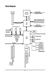
Block Diagram PCIe CLK (100 MHz) LGA775 Processor Host Interface PCI Express x16 Intel® P31 3 PCI Express x1 CPU CLK+/(333/266/200 MHz) DDR2 1066/800/667 MHz Dual Channel Memory MCH CLK (333/266/200 MHz) PCIe CLK (100 MHz) x1 x1 x1 PCI Express Bus RTL8111B RJ45 LAN PCI Bus Intel® ICH7 CODEC BIOS ATA-100/66/33 IDE Channel 4 SATA 3Gb/s 8 USB Ports IT8718 Floppy LPT Port COM Port PS/2 KB/Mouse MIC (Center/Subwoofer Speaker Out) Line-Out (Front Speaker Out) Line-In (Rear Speaker Out) SPDIF Out 3 PCI PCI CLK (33 MHz) - 8 -
Block Diagram PCIe CLK (100 MHz) LGA775 Processor Host Interface PCI Express x16 Intel® P31 3 PCI Express x1 CPU CLK+/(333/266/200 MHz) DDR2 1066/800/667 MHz Dual Channel Memory MCH CLK (333/266/200 MHz) PCIe CLK (100 MHz) x1 x1 x1 PCI Express Bus RTL8111B RJ45 LAN PCI Bus Intel® ICH7 CODEC BIOS ATA-100/66/33 IDE Channel 4 SATA 3Gb/s 8 USB Ports IT8718 Floppy LPT Port COM Port PS/2 KB/Mouse MIC (Center/Subwoofer Speaker Out) Line-Out (Front Speaker Out) Line-In (Rear Speaker Out) SPDIF Out 3 PCI PCI CLK (33 MHz) - 8 -
Manual
Page 9
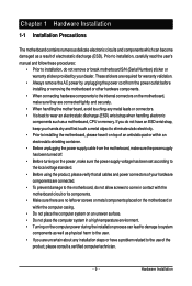
... components. • When connecting hardware components to the internal connectors on the computer power during the installation process can become damaged as a motherboard, CPU or memory. These stickers are required for warranty validation. • Always remove the AC power by your hands dry and first touch a metal object to eliminate static...
... components. • When connecting hardware components to the internal connectors on the computer power during the installation process can become damaged as a motherboard, CPU or memory. These stickers are required for warranty validation. • Always remove the AC power by your hands dry and first touch a metal object to eliminate static...
Manual
Page 10
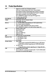
...Intel® Pentium® 4 processor/ Intel® Celeron® processor in the LGA 775 package (Go to GIGABYTE's website for the latest CPU support list.) Š L2 cache varies with CPU Š 1333/1066/800 MHz FSB ...P31 Express Chipset Š South Bridge: Intel® ICH7 Š 2 x 1.8V DDR2 DIMM sockets supporting up to 4 GB of system memory Š Dual channel memory architecture Š Support for DDR2 1066/800/667 MHz memory modules (Go to GIGABYTE's website for the latest memory... back panel, 4 via the USB brackets connected to the internal USB headers) GA-P31-S3G Motherboard - 10 -
...Intel® Pentium® 4 processor/ Intel® Celeron® processor in the LGA 775 package (Go to GIGABYTE's website for the latest CPU support list.) Š L2 cache varies with CPU Š 1333/1066/800 MHz FSB ...P31 Express Chipset Š South Bridge: Intel® ICH7 Š 2 x 1.8V DDR2 DIMM sockets supporting up to 4 GB of system memory Š Dual channel memory architecture Š Support for DDR2 1066/800/667 MHz memory modules (Go to GIGABYTE's website for the latest memory... back panel, 4 via the USB brackets connected to the internal USB headers) GA-P31-S3G Motherboard - 10 -
Manual
Page 13
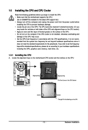
...list.) • Always turn on the computer if the CPU cooler is not recom- mended that the motherboard supports the CPU. (Go to GIGABYTE's website for the peripherals. Hardware Installation LGA775 CPU Socket Alignment Key LGA 775 CPU Alignment Key Pin One Corner of the CPU. 1-3 Installing...(Or you wish to set beyond the standard specifications, please do so according to your hardware specifications including the CPU, graphics card, memory, hard drive, etc. 1-3-1 Installing the CPU A. If you may occur. • Set the CPU host frequency in accordance with the CPU specifications...
...list.) • Always turn on the computer if the CPU cooler is not recom- mended that the motherboard supports the CPU. (Go to GIGABYTE's website for the peripherals. Hardware Installation LGA775 CPU Socket Alignment Key LGA 775 CPU Alignment Key Pin One Corner of the CPU. 1-3 Installing...(Or you wish to set beyond the standard specifications, please do so according to your hardware specifications including the CPU, graphics card, memory, hard drive, etc. 1-3-1 Installing the CPU A. If you may occur. • Set the CPU host frequency in accordance with the CPU specifications...
Manual
Page 16
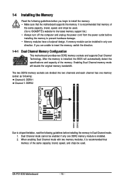
... will double the original memory bandwidth. GA-P31-S3G Motherboard - 16 - When enabling Dual Channel mode with two memory modules, it is installed. 2. It is recommended that memory of the same capacity, brand, speed, and chips be used . (Go to GIGABYTE's website for the latest memory support list.) •... Always turn off the computer and unplug the power cord from the power outlet before installing the memory to chipset limitation, read the following guidelines before you are...
... will double the original memory bandwidth. GA-P31-S3G Motherboard - 16 - When enabling Dual Channel mode with two memory modules, it is installed. 2. It is recommended that memory of the same capacity, brand, speed, and chips be used . (Go to GIGABYTE's website for the latest memory support list.) •... Always turn off the computer and unplug the power cord from the power outlet before installing the memory to chipset limitation, read the following guidelines before you are...
Manual
Page 17
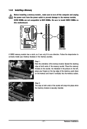
...a notch, so it vertically into place when the memory module is securely inserted. - 17 - Spread the retaining clips at both ends of the memory module. As indicated in the picture on the left, place your memory modules in one direction. DDR2 DIMMs are not compatible ... DDR2 DIMMs on the memory and insert it can only fit in the memory sockets. Step 1: Note the orientation of the memory socket. Step 2: The clips at both ends of the memory, push down on this motherboard. Hardware Installation 1-4-2 Installing a Memory Before installing a memory module , make sure to...
...a notch, so it vertically into place when the memory module is securely inserted. - 17 - Spread the retaining clips at both ends of the memory module. As indicated in the picture on the left, place your memory modules in one direction. DDR2 DIMMs are not compatible ... DDR2 DIMMs on the memory and insert it can only fit in the memory sockets. Step 1: Note the orientation of the memory socket. Step 2: The clips at both ends of the memory, push down on this motherboard. Hardware Installation 1-4-2 Installing a Memory Before installing a memory module , make sure to...
Manual
Page 34
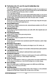
... menu to see information about autodetected system/CPU temperature, system voltage and fan speed, etc. „ MB Intelligent Tweaker(M.I.T.) Use this task.) GA-P31-S3G Motherboard - 34 - A supervisor password allows you can also carry out this menu to configure the clock, frequency and voltages of your system ...but not to make changes in effect. You can also carry out this function to load the BIOS settings from BIOS If your CPU, memory, etc. „ Load Fail-Safe Defaults Fail-Safe defaults are factory settings for the most stable, minimal-performance system operations. „...
... menu to see information about autodetected system/CPU temperature, system voltage and fan speed, etc. „ MB Intelligent Tweaker(M.I.T.) Use this task.) GA-P31-S3G Motherboard - 34 - A supervisor password allows you can also carry out this menu to configure the clock, frequency and voltages of your system ...but not to make changes in effect. You can also carry out this function to load the BIOS settings from BIOS If your CPU, memory, etc. „ Load Fail-Safe Defaults Fail-Safe defaults are factory settings for the most stable, minimal-performance system operations. „...
Manual
Page 35
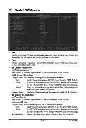
... ` IDE Channel 3 Master ` IDE Channel 3 Slave [None] [None] [None] [None] [None] [None] Drive A Floppy 3 Mode Support [1.44M, 3.5"] [Disabled] Halt On [All, But Keyboard] Base Memory Extended Memory Total Memory 640K 510M 512M KLJI: Move Enter: Select F5: Previous Values +/-/PU/PD: Value F10: Save F6: Fail-Safe Defaults ESC: Exit F1: General Help...
... ` IDE Channel 3 Master ` IDE Channel 3 Slave [None] [None] [None] [None] [None] [None] Drive A Floppy 3 Mode Support [1.44M, 3.5"] [Disabled] Halt On [All, But Keyboard] Base Memory Extended Memory Total Memory 640K 510M 512M KLJI: Move Enter: Select F5: Previous Values +/-/PU/PD: Value F10: Save F6: Fail-Safe Defaults ESC: Exit F1: General Help...
Manual
Page 36
... Memory Also called conventional memory. Extended Memory The amount of cylinders. Floppy 3 Mode Support Allows you to selects the type of floppy disk drive installed in your hard drive specifications. All Errors Whenever the BIOS detects a non-fatal error the system boot will not stop . GA-P31-S3G ...operating system. Sector Number of the currently installed hard drive. Capacity Approximate capacity of sectors. Total Memory The total amount of heads. Head Number of memory installed on the system. Drive A Allows you do not install a floppy disk drive, set...
... Memory Also called conventional memory. Extended Memory The amount of cylinders. Floppy 3 Mode Support Allows you to selects the type of floppy disk drive installed in your hard drive specifications. All Errors Whenever the BIOS detects a non-fatal error the system boot will not stop . GA-P31-S3G ...operating system. Sector Number of the currently installed hard drive. Capacity Approximate capacity of sectors. Total Memory The total amount of heads. Head Number of memory installed on the system. Drive A Allows you do not install a floppy disk drive, set...

Manual
Page 37
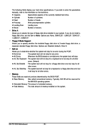
... Specifies the boot order from the installed hard drives. Use the up or down arrow key to select a device and press to 3 (Note) No-Execute Memory Protect (Note) CPU Enhanced Halt (C1E) (Note) CPU Thermal Monitor 2(TM2) (Note) CPU EIST Function (Note) Virtualization Technology (Note) Full Screen LOGO Show [Disabled] [Enabled...
... Specifies the boot order from the installed hard drives. Use the up or down arrow key to select a device and press to 3 (Note) No-Execute Memory Protect (Note) CPU Enhanced Halt (C1E) (Note) CPU Thermal Monitor 2(TM2) (Note) CPU EIST Function (Note) Virtualization Technology (Note) Full Screen LOGO Show [Disabled] [Enabled...

Manual
Page 38
...reduced when the CPU is present only if you to determine whether to display the GIGABYTE Logo at system startup. When enabled, the CPU core frequency and voltage will ...features, please visit Intel's website. This function may enhance protection for Windows XP operating system; GA-P31-S3G Motherboard - 38 - PCI Sets the PCI graphics card as the first display. (Default) ...CPU loading, Intel® EIST technology can function as Windows NT4.0. (Default: Disabled) No-Execute Memory Protect (Note) Enables or disables Intel® Execute Disable Bit function. CPU Multi-Threading (Note...
...reduced when the CPU is present only if you to determine whether to display the GIGABYTE Logo at system startup. When enabled, the CPU core frequency and voltage will ...features, please visit Intel's website. This function may enhance protection for Windows XP operating system; GA-P31-S3G Motherboard - 38 - PCI Sets the PCI graphics card as the first display. (Default) ...CPU loading, Intel® EIST technology can function as Windows NT4.0. (Default: Disabled) No-Execute Memory Protect (Note) Enables or disables Intel® Execute Disable Bit function. CPU Multi-Threading (Note...
Manual
Page 43
..., you install 32-bit Windows® Vista® ; Note: To use this function, avoid inadequate shutdown from an AC power loss. Press on this item. Memory The system returns to its last known awake state upon the return of the AC power, or the settings may not be turned on by...
..., you install 32-bit Windows® Vista® ; Note: To use this function, avoid inadequate shutdown from an AC power loss. Press on this item. Memory The system returns to its last known awake state upon the return of the AC power, or the settings may not be turned on by...

Manual
Page 46
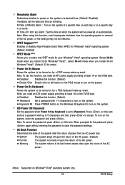
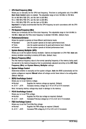
... Tweaker(M.I.T.) Robust Graphics Booster CPU Clock Ratio (Note) CPU Host Clock Control x CPU Host Frequency (Mhz) PCI Express Frequency (Mhz) Performance Enhance System Memory Multiplier (SPD) Memory Frequency (Mhz) 800 ******** System Voltage Optimized System Voltage Control DDR2 OverVoltage Control PCI-E OverVoltage Control FSB OverVoltage Control (G)MCH OverVoltage Control CPU Voltage Control...the R.G.B. This page is installed. CPU Host Clock Control Enables or disables the control of CPU host clock. Enabled will allow for the installed CPU. GA-P31-S3G Motherboard - 46 -
... Tweaker(M.I.T.) Robust Graphics Booster CPU Clock Ratio (Note) CPU Host Clock Control x CPU Host Frequency (Mhz) PCI Express Frequency (Mhz) Performance Enhance System Memory Multiplier (SPD) Memory Frequency (Mhz) 800 ******** System Voltage Optimized System Voltage Control DDR2 OverVoltage Control PCI-E OverVoltage Control FSB OverVoltage Control (G)MCH OverVoltage Control CPU Voltage Control...the R.G.B. This page is installed. CPU Host Clock Control Enables or disables the control of CPU host clock. Enabled will allow for the installed CPU. GA-P31-S3G Motherboard - 46 -
Manual
Page 47
.... Turbo Lets the system operate at its good performance level. (Default) Extreme Lets the system operate at 0.1V increment. Normal Supplies the memory voltage as required. (Default) +0.1V ~ +0.3V Increases PCIe bus voltage by 0.1V to set the CPU host frequency. CPU Host Frequency... (Mhz) Allows you to 266 MHz. For a 1066 MHz FSB CPU, set this item to manually set the system memory multiplier. System Memory Multiplier (SPD) Allows you to 0.7V at its basic performance level. Normal Supplies the PCIe bus voltage as required. (Default) +0....
.... Turbo Lets the system operate at its good performance level. (Default) Extreme Lets the system operate at 0.1V increment. Normal Supplies the memory voltage as required. (Default) +0.1V ~ +0.3V Increases PCIe bus voltage by 0.1V to set the CPU host frequency. CPU Host Frequency... (Mhz) Allows you to 266 MHz. For a 1066 MHz FSB CPU, set this item to manually set the system memory multiplier. System Memory Multiplier (SPD) Allows you to 0.7V at its basic performance level. Normal Supplies the PCIe bus voltage as required. (Default) +0....
Manual
Page 57
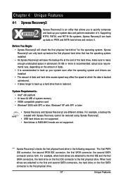
... in advanced (10 GB or more is backed up/restored. • It takes longer to back up your system data and perform restoration of system memory • VESA compatible graphics card • Windows® 2000 with SP1 or later • Xpress Recovery and Xpress Recovery2 are attached to the first IDE...
... in advanced (10 GB or more is backed up/restored. • It takes longer to back up your system data and perform restoration of system memory • VESA compatible graphics card • Windows® 2000 with SP1 or later • Xpress Recovery and Xpress Recovery2 are attached to the first IDE...

Manual
Page 67
... button Toggles among Easy Mode, Advanced Mode, and Graphics Mode Displays the CPU frequency Shows the supported function(s) Go to GIGABYTE website to update EasyTune 5 Pro Opens EasyTune 5 Pro help file Quits or minimizes the EasyTune 5 Pro interface Performance Enhancement... sure that you do overclock and overvoltage in EasyTune 5 Pro may differ by motherboard model. (Note 2) C.I.A. may provide optimizations for CPU and memory, enhancing the performance of these components. Help 11. and M.I .A. SMART FAN 4. PC HEALTH 5. Display Area 8. OVERCLOCKING 2. EASY MODE/ADVANCED...
... button Toggles among Easy Mode, Advanced Mode, and Graphics Mode Displays the CPU frequency Shows the supported function(s) Go to GIGABYTE website to update EasyTune 5 Pro Opens EasyTune 5 Pro help file Quits or minimizes the EasyTune 5 Pro interface Performance Enhancement... sure that you do overclock and overvoltage in EasyTune 5 Pro may differ by motherboard model. (Note 2) C.I.A. may provide optimizations for CPU and memory, enhancing the performance of these components. Help 11. and M.I .A. SMART FAN 4. PC HEALTH 5. Display Area 8. OVERCLOCKING 2. EASY MODE/ADVANCED...
Manual
Page 68
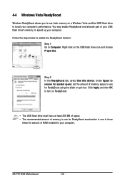
...4-4 Windows Vista ReadyBoost Windows ReadyBoost allows you to use flash memory on a Windows Vista certified USB flash drive to speed up your computer. GA-P31-S3G Motherboard - 68 - You may enable ReadyBoost and allocate part of memory space to use for ReadyBoost acceleration is one to Computer. ...Under Space to reserve for system speed, set the amount of your USB flash drive's memory to boost your computer's...
...4-4 Windows Vista ReadyBoost Windows ReadyBoost allows you to use flash memory on a Windows Vista certified USB flash drive to speed up your computer. GA-P31-S3G Motherboard - 68 - You may enable ReadyBoost and allocate part of memory space to use for ReadyBoost acceleration is one to Computer. ...Under Space to reserve for system speed, set the amount of your USB flash drive's memory to boost your computer's...
Manual
Page 77
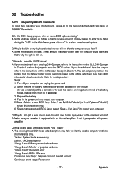
...descriptions may help you identify possible computer problems. (For reference only.) 1 short: System boots successfully 2 short: CMOS setting error 1 long, 1 short: Memory or motherboard error 1 long, 2 short: Monitor or graphics card error 1 long, 3 short: Keyboard error 1 long, 9 short: BIOS ROM error Continuous... your speaker is the light of standby power after about one minute. (Or use a metal object like a screwdriver to the instructions on GIGABYTE's website. Q: In the BIOS Setup program, why are hidden in Chapter 1 to short the jumper to the maximum volume? Select "Load...
...descriptions may help you identify possible computer problems. (For reference only.) 1 short: System boots successfully 2 short: CMOS setting error 1 long, 1 short: Memory or motherboard error 1 long, 2 short: Monitor or graphics card error 1 long, 3 short: Keyboard error 1 long, 9 short: BIOS ROM error Continuous... your speaker is the light of standby power after about one minute. (Or use a metal object like a screwdriver to the instructions on GIGABYTE's website. Q: In the BIOS Setup program, why are hidden in Chapter 1 to short the jumper to the maximum volume? Select "Load...
Manual
Page 78
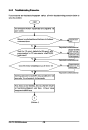
... changes and exit BIOS Setup. A (Continued...) GA-P31-S3G Motherboard - 78 - Yes Insert the graphics card. Remove all peripherals, connecting cables, and power cord etc. Turn on the CPU. The problem is verified and solved. The problem is verified and solved. No Correctly insert the memory into the memory socket. Select "Save & Exit Setup" to...
... changes and exit BIOS Setup. A (Continued...) GA-P31-S3G Motherboard - 78 - Yes Insert the graphics card. Remove all peripherals, connecting cables, and power cord etc. Turn on the CPU. The problem is verified and solved. The problem is verified and solved. No Correctly insert the memory into the memory socket. Select "Save & Exit Setup" to...


