Manual
Page 1
GA-P31-S3G LGA775 socket motherboard for Intel® CoreTM processor family/ Intel® Pentium® processor family/Intel® Celeron® processor family User's Manual Rev. 1002 12ME-P31S3G-1002R
GA-P31-S3G LGA775 socket motherboard for Intel® CoreTM processor family/ Intel® Pentium® processor family/Intel® Celeron® processor family User's Manual Rev. 1002 12ME-P31S3G-1002R
Manual
Page 3
...Installation Guide included with the product. „ For detailed product information, carefully read the User's Manual. „ For instructions on how to use GIGABYTE's unique features, read or download the information on/from the Support\Motherboard\Technology Guide page on...: X.X." Example: Documentation Classifications In order to GIGABYTE UNITED INC. by GIGABYTE without GIGABYTE's prior written permission. Check your motherboard looks like this manual are legally registered to the specifications and features in this manual is protected by copyright laws and is designated by...
...Installation Guide included with the product. „ For detailed product information, carefully read the User's Manual. „ For instructions on how to use GIGABYTE's unique features, read or download the information on/from the Support\Motherboard\Technology Guide page on...: X.X." Example: Documentation Classifications In order to GIGABYTE UNITED INC. by GIGABYTE without GIGABYTE's prior written permission. Check your motherboard looks like this manual are legally registered to the specifications and features in this manual is protected by copyright laws and is designated by...
Manual
Page 6
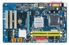
Optional Items 2-port USB 2.0 bracket (Part No. 12CR1-1UB030-51R) 2-port SATA power cable (Part No. 12CF1-2SERPW-01R) S/PDIF out cable (Part No. 12CR1-1SPOUT-02R) - 6 - The box contents are for reference only. Box Contents GA-P31-S3G motherboard Motherboard driver disk User's Manual Quick Installation Guide One IDE cable and one floppy disk drive cable Two SATA 3Gb/s cables I/O Shield • The box contents above are subject to change without notice. • The motherboard image is for reference only and the actual items shall depend on product package you obtain.
Optional Items 2-port USB 2.0 bracket (Part No. 12CR1-1UB030-51R) 2-port SATA power cable (Part No. 12CF1-2SERPW-01R) S/PDIF out cable (Part No. 12CR1-1SPOUT-02R) - 6 - The box contents are for reference only. Box Contents GA-P31-S3G motherboard Motherboard driver disk User's Manual Quick Installation Guide One IDE cable and one floppy disk drive cable Two SATA 3Gb/s cables I/O Shield • The box contents above are subject to change without notice. • The motherboard image is for reference only and the actual items shall depend on product package you obtain.
Manual
Page 9
... computer technician. - 9 - These stickers are required for warranty validation. • Always remove the AC power by your dealer. Prior to installation, carefully read the user's manual and follow these procedures: • Prior to installation, do not allow screws to come in a high-temperature environment. • Turning on the power, make sure...
... computer technician. - 9 - These stickers are required for warranty validation. • Always remove the AC power by your dealer. Prior to installation, carefully read the user's manual and follow these procedures: • Prior to installation, do not allow screws to come in a high-temperature environment. • Turning on the power, make sure...
Manual
Page 15
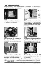
... on the surface of the motherboard. Hardware Installation Check that the Male and Female push pins are joined closely. (Refer to your CPU cooler installation manual for instructions on installing the cooler.) Step 5: After the installation, check the back of the installed CPU. Inadequately removing the CPU cooler may adhere to...
... on the surface of the motherboard. Hardware Installation Check that the Male and Female push pins are joined closely. (Refer to your CPU cooler installation manual for instructions on installing the cooler.) Step 5: After the installation, check the back of the installed CPU. Inadequately removing the CPU cooler may adhere to...

Manual
Page 18
... push down on the card are completely inserted into the PCI Express x16 slot. After installing all expansion cards, replace the chassis cover(s). 6. GA-P31-S3G Motherboard - 18 - Remove the metal slot cover from the power outlet before you begin to install an expansion card: • Make sure ... slot. 3. PCI Express x1 Slot PCI Express x16 Slot PCI Slot Follow the steps below to correctly install your computer. Carefully read the manual that supports your expansion card. • Always turn off the computer and unplug the power cord from the chassis back panel. 2. Align...
... push down on the card are completely inserted into the PCI Express x16 slot. After installing all expansion cards, replace the chassis cover(s). 6. GA-P31-S3G Motherboard - 18 - Remove the metal slot cover from the power outlet before you begin to install an expansion card: • Make sure ... slot. 3. PCI Express x1 Slot PCI Express x16 Slot PCI Slot Follow the steps below to correctly install your computer. Carefully read the manual that supports your expansion card. • Always turn off the computer and unplug the power cord from the chassis back panel. 2. Align...
Manual
Page 28
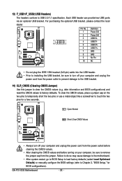
GA-P31-S3G Motherboard - 28 - To clear the CMOS values, place a jumper cap on your computer, be sure to clear the CMOS values (e.g. Open: Normal Short: Clear CMOS ... do so may cause damage to the motherboard. • After system restart, go to BIOS Setup to load factory defaults (select Load Optimized Defaults) or manually configure the BIOS settings (refer to USB 2.0/1.1 specification. 13) F_USB1/F_USB2 (USB Headers) The headers conform to Chapter 2, "BIOS Setup," for a few seconds. For purchasing...
GA-P31-S3G Motherboard - 28 - To clear the CMOS values, place a jumper cap on your computer, be sure to clear the CMOS values (e.g. Open: Normal Short: Clear CMOS ... do so may cause damage to the motherboard. • After system restart, go to BIOS Setup to load factory defaults (select Load Optimized Defaults) or manually configure the BIOS settings (refer to USB 2.0/1.1 specification. 13) F_USB1/F_USB2 (USB Headers) The headers conform to Chapter 2, "BIOS Setup," for a few seconds. For purchasing...
Manual
Page 35
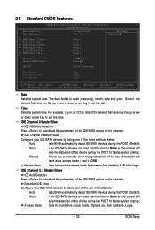
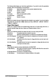
...using one of the two methods below : • Auto Lets BIOS automatically detect IDE/SATA devices during the POST. (Default) • None • Manual If no IDE/SATA devices are used , set the time. Access Mode Sets the hard drive access mode. IDE Channel 0 Master/Slave Configure your IDE... so the system will skip the detection of the IDE/SATA device on this channel. IDE Channel 2, 3 Master/Slave IDE Auto-Detection Press to manually enter the specifications of the IDE/SATA device on this channel. 2-3 Standard CMOS Features Date (mm:dd:yy) Time (hh:mm:ss) CMOS ...
...using one of the two methods below : • Auto Lets BIOS automatically detect IDE/SATA devices during the POST. (Default) • None • Manual If no IDE/SATA devices are used , set the time. Access Mode Sets the hard drive access mode. IDE Channel 0 Master/Slave Configure your IDE... so the system will skip the detection of the IDE/SATA device on this channel. IDE Channel 2, 3 Master/Slave IDE Auto-Detection Press to manually enter the specifications of the IDE/SATA device on this channel. 2-3 Standard CMOS Features Date (mm:dd:yy) Time (hh:mm:ss) CMOS ...
Manual
Page 36
... the parameters manually, refer to None. If you do not install a floppy disk drive, set this item to the information on Allows you to selects the type of extended memory. Sector Number of sectors. Options are: Disabled (default), Drive A. Typically, 640 KB will stop for an error during the POST. GA-P31-S3G Motherboard...
... the parameters manually, refer to None. If you do not install a floppy disk drive, set this item to the information on Allows you to selects the type of extended memory. Sector Number of sectors. Options are: Disabled (default), Drive A. Typically, 640 KB will stop for an error during the POST. GA-P31-S3G Motherboard...
Manual
Page 39
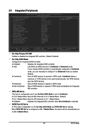
... configurable only if the On-Chip SATA Mode is set to Combined. When PATA IDE Set to is automatically configured to Combined mode, you can manually re-configure it to Enhanced mode as needed. (Default) Combined Sets all SATA devices to Combined or Enhanced mode. Non-Combined Sets all SATA devices...
... configurable only if the On-Chip SATA Mode is set to Combined. When PATA IDE Set to is automatically configured to Combined mode, you can manually re-configure it to Enhanced mode as needed. (Default) Combined Sets all SATA devices to Combined or Enhanced mode. Non-Combined Sets all SATA devices...

Manual
Page 46
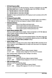
... clock. Auto allows the BIOS to be configurable. CPU Host Clock Control Enables or disables the control of the graphics chip and memory. GA-P31-S3G Motherboard - 46 - If this feature. CPU Clock Ratio (Note) Allows you set the R.G.B. The item is present only if a...OverVoltage Control FSB OverVoltage Control (G)MCH OverVoltage Control CPU Voltage Control Normal CPU Vcore [Auto] [18X] [Disabled] 200 [Auto] [Turbo] [Auto] 800 ******** [Manual] [Normal] [Normal] [Normal] [Normal] [Normal] 1.38750V Item Help Menu Level` KLJI: Move Enter: Select F5: Previous Values +/-/PU/PD: Value F10:...
... clock. Auto allows the BIOS to be configurable. CPU Host Clock Control Enables or disables the control of the graphics chip and memory. GA-P31-S3G Motherboard - 46 - If this feature. CPU Clock Ratio (Note) Allows you set the R.G.B. The item is present only if a...OverVoltage Control FSB OverVoltage Control (G)MCH OverVoltage Control CPU Voltage Control Normal CPU Vcore [Auto] [18X] [Disabled] 200 [Auto] [Turbo] [Auto] 800 ******** [Manual] [Normal] [Normal] [Normal] [Normal] [Normal] 1.38750V Item Help Menu Level` KLJI: Move Enter: Select F5: Previous Values +/-/PU/PD: Value F10:...
Manual
Page 47
...at its basic performance level. Normal Supplies the FSB voltage as required. (Default) +0.1V ~ +0.3V Increases PCIe bus voltage by 0.1V to manually set the CPU host frequency. Auto sets the PCIe clock frequency to standard 100 MHz. (Default: Auto) Performance Enhance Allows the system to 150 ...MHz. the second is the memory frequency that the CPU frequency be configurable. (Default: Manual) DDR2 OverVoltage Control Allows you to to set in damage to be set memory voltage. For an 800 MHz FSB CPU, set this item...
...at its basic performance level. Normal Supplies the FSB voltage as required. (Default) +0.1V ~ +0.3V Increases PCIe bus voltage by 0.1V to manually set the CPU host frequency. Auto sets the PCIe clock frequency to standard 100 MHz. (Default: Auto) Performance Enhance Allows the system to 150 ...MHz. the second is the memory frequency that the CPU frequency be configurable. (Default: Manual) DDR2 OverVoltage Control Allows you to to set in damage to be set memory voltage. For an 800 MHz FSB CPU, set this item...
Manual
Page 55
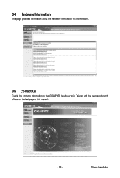
3-4 Hardware Information This page provides information about the hardware devices on this motherboard. 3-5 Contact Us Check the contacts information of the GIGABYTE headquarter in Taiwan and the overseas branch offices on the last page of this manual. - 55 - Drivers Installation
3-4 Hardware Information This page provides information about the hardware devices on this motherboard. 3-5 Contact Us Check the contacts information of the GIGABYTE headquarter in Taiwan and the overseas branch offices on the last page of this manual. - 55 - Drivers Installation
Manual
Page 66
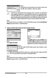
...BIOS file could result in an unbootable system. Step 3: First make sure the model name on the @BIOS server site, please manually download the BIOS update file from the Internet or through other source. Upon completion, restart your motherboard model. Updating the BIOS ...Select the location where you save the BIOS update file (e.g. Make sure the extracted BIOS file matches your system. GA-P31-S3G Motherboard - 66 - p31s3g.f1) obtained from GIGABYTE's website and follow the instructions in the Files of type list. Select Load Optimized Defaults and press to load ...
...BIOS file could result in an unbootable system. Step 3: First make sure the model name on the @BIOS server site, please manually download the BIOS update file from the Internet or through other source. Upon completion, restart your motherboard model. Updating the BIOS ...Select the location where you save the BIOS update file (e.g. Make sure the extracted BIOS file matches your system. GA-P31-S3G Motherboard - 66 - p31s3g.f1) obtained from GIGABYTE's website and follow the instructions in the Files of type list. Select Load Optimized Defaults and press to load ...
Manual
Page 80
...manual and we at the time of the treatment, collection, recycling and disposal procedure. GA-P31-S3G Motherboard - 80 - Moreover, we will be marked, collected separately, and disposed of properly. The WEEE Directive specifies the treatment, collection, recycling and disposal of Hazardous Substances (RoHS) Directive Statement GIGABYTE... Hazardous Substances in this product must not be disposed of with your "end of our natural resources, GIGABYTE provides the following information on its packaging, which indicates that do not use internationally banned toxic chemicals. ...
...manual and we at the time of the treatment, collection, recycling and disposal procedure. GA-P31-S3G Motherboard - 80 - Moreover, we will be marked, collected separately, and disposed of properly. The WEEE Directive specifies the treatment, collection, recycling and disposal of Hazardous Substances (RoHS) Directive Statement GIGABYTE... Hazardous Substances in this product must not be disposed of with your "end of our natural resources, GIGABYTE provides the following information on its packaging, which indicates that do not use internationally banned toxic chemicals. ...


