Manual
Page 11
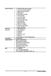
Internal Connectors Š 1 x 24-pin ATX main power connector Š 1 x 4-pin ATX 12V power connector Š 1 x floppy disk drive connector Š 1 x IDE connector Š 4 x SATA 3Gb/s connectors Š 1 x CPU fan header Š...138; 1 x front panel audio header Š 1 x CD In connector Š 1 x S/PDIF Out header Š 2 x USB 2.0/1.1 headers Š 1 x chassis intrusion header Š 1 x power LED header Back Panel Š 1 x PS/2 keyboard port Connectors Š 1 x PS/2 mouse port Š 1 x parallel port Š 1 x serial port Š 4 x USB 2.0/1.1 ports Š ...
Internal Connectors Š 1 x 24-pin ATX main power connector Š 1 x 4-pin ATX 12V power connector Š 1 x floppy disk drive connector Š 1 x IDE connector Š 4 x SATA 3Gb/s connectors Š 1 x CPU fan header Š...138; 1 x front panel audio header Š 1 x CD In connector Š 1 x S/PDIF Out header Š 2 x USB 2.0/1.1 headers Š 1 x chassis intrusion header Š 1 x power LED header Back Panel Š 1 x PS/2 keyboard port Connectors Š 1 x PS/2 mouse port Š 1 x parallel port Š 1 x serial port Š 4 x USB 2.0/1.1 ports Š ...
Manual
Page 25
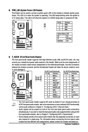
... header supports Intel High Definition audio (HD) and AC'97 audio. For HD Front Panel Audio: Pin No. 8) PWR_LED (System Power LED Header) This header can be present on when the system is in S1 sleep state. For information about connecting the front panel audio module... via the audio software in Chapter 5, "Configuring 2/4/5.1-Channel Audio." • Audio signals will make the device unable to connect a system power LED on each wire instead of the motherboard header. Make sure the wire assignments of the module connector match the pin assignments of a single plug...
... header supports Intel High Definition audio (HD) and AC'97 audio. For HD Front Panel Audio: Pin No. 8) PWR_LED (System Power LED Header) This header can be present on when the system is in S1 sleep state. For information about connecting the front panel audio module... via the audio software in Chapter 5, "Configuring 2/4/5.1-Channel Audio." • Audio signals will make the device unable to connect a system power LED on each wire instead of the motherboard header. Make sure the wire assignments of the module connector match the pin assignments of a single plug...
Manual
Page 26
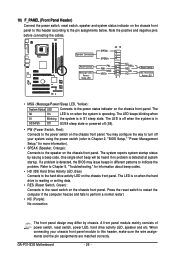
.... You may configure the way to turn off (S5). • PW (Power Switch, Red): Connects to the power switch on the chassis front panel to the pin assignments below. The system reports system startup status by chassis. GA-P31-S3G Motherboard - 26 - The S0 On LED is reading or writing data. • RES (Reset Switch, Green...
.... You may configure the way to turn off (S5). • PW (Power Switch, Red): Connects to the power switch on the chassis front panel to the pin assignments below. The system reports system startup status by chassis. GA-P31-S3G Motherboard - 26 - The S0 On LED is reading or writing data. • RES (Reset Switch, Green...


