
Manual
Page 1
...F5: Previous Values +/-/PU/PD: Value F10: Save F6: Fail-Safe Defaults ESC: Exit F1: General Help F7: Optimized Defaults The BIOS Setup menus described here may differ from the exact settings for storing your computer and press to the SATA disk 4. Set PCH SATA Control... Mode under the Integrated Peripherals menu to enable the Intel® Smart Response Technology: 1. Installing the operating system and drivers to enter BIOS Setup during the POST (Power-On Self-Test). Installing a conventional SATA hard disk and a solid-state drive (SSD): Besides the conventional ...
...F5: Previous Values +/-/PU/PD: Value F10: Save F6: Fail-Safe Defaults ESC: Exit F1: General Help F7: Optimized Defaults The BIOS Setup menus described here may differ from the exact settings for storing your computer and press to the SATA disk 4. Set PCH SATA Control... Mode under the Integrated Peripherals menu to enable the Intel® Smart Response Technology: 1. Installing the operating system and drivers to enter BIOS Setup during the POST (Power-On Self-Test). Installing a conventional SATA hard disk and a solid-state drive (SSD): Besides the conventional ...

Manual
Page 2
...fication area and double-click it to install the operating system. Installing the operating system and drivers to the SATA disk: After setting the BIOS, you can begin to open the Intel Rapid Storage Technology utility. - 2 -
...fication area and double-click it to install the operating system. Installing the operating system and drivers to the SATA disk: After setting the BIOS, you can begin to open the Intel Rapid Storage Technology utility. - 2 -

Manual
Page 3
For product-related information, check on our website at: http://www.gigabyte.com Identifying Your Motherboard Revision The revision number on your motherboard revision before updating motherboard BIOS, drivers, or when looking for technical information. Example: Disclaimer Information in this...be made by any form or by GIGABYTE without GIGABYTE's prior written permission. Check your motherboard looks like this product, GIGABYTE provides the following types of documentations: For quick set-up of GIGABYTE. Documentation Classifications In order to the specifications...
For product-related information, check on our website at: http://www.gigabyte.com Identifying Your Motherboard Revision The revision number on your motherboard revision before updating motherboard BIOS, drivers, or when looking for technical information. Example: Disclaimer Information in this...be made by any form or by GIGABYTE without GIGABYTE's prior written permission. Check your motherboard looks like this product, GIGABYTE provides the following types of documentations: For quick set-up of GIGABYTE. Documentation Classifications In order to the specifications...

Manual
Page 4
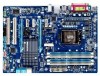
Table of Contents Box Contents...6 Optional Items...6 GA-Z68AP-D3 Motherboard Layout 7 GA-Z68AP-D3 Motherboard Block Diagram 8 Chapter 1 Hardware Installation 9 1-1 Installation Precautions 9 1-2 Product Specifications 10 1-3 Installing the CPU and CPU ... an Expansion Card 18 1-6 Back Panel Connectors 19 1-7 Internal Connectors 21 Chapter 2 BIOS Setup 29 2-1 Startup Screen 30 2-2 The Main Menu 31 2-3 MB Intelligent Tweaker(M.I.T 33 2-4 Standard CMOS Features 41 2-5 Advanced BIOS Features 43 2-6 Integrated Peripherals 45 2-7 Power Management Setup 48 2-8 PC Health Status ...
Table of Contents Box Contents...6 Optional Items...6 GA-Z68AP-D3 Motherboard Layout 7 GA-Z68AP-D3 Motherboard Block Diagram 8 Chapter 1 Hardware Installation 9 1-1 Installation Precautions 9 1-2 Product Specifications 10 1-3 Installing the CPU and CPU ... an Expansion Card 18 1-6 Back Panel Connectors 19 1-7 Internal Connectors 21 Chapter 2 BIOS Setup 29 2-1 Startup Screen 30 2-2 The Main Menu 31 2-3 MB Intelligent Tweaker(M.I.T 33 2-4 Standard CMOS Features 41 2-5 Advanced BIOS Features 43 2-6 Integrated Peripherals 45 2-7 Power Management Setup 48 2-8 PC Health Status ...

Manual
Page 5
... 56 3-4 Contact...57 3-5 System...57 3-6 Download Center 58 3-7 New Utilities...58 Chapter 4 Unique Features 59 4-1 Xpress Recovery2 59 4-2 BIOS Update Utilities 62 4-2-1 Updating the BIOS with the Q-Flash Utility 62 4-2-2 Updating the BIOS with the @BIOS Utility 65 4-3 EasyTune 6...66 4-4 Q-Share...67 4-5 Smart 6™ ...68 4-6 Auto Green...72 4-7 eXtreme Hard Drive (X.H.D 73 4-8 Cloud OC...
... 56 3-4 Contact...57 3-5 System...57 3-6 Download Center 58 3-7 New Utilities...58 Chapter 4 Unique Features 59 4-1 Xpress Recovery2 59 4-2 BIOS Update Utilities 62 4-2-1 Updating the BIOS with the Q-Flash Utility 62 4-2-2 Updating the BIOS with the @BIOS Utility 65 4-3 EasyTune 6...66 4-4 Q-Share...67 4-5 Smart 6™ ...68 4-6 Auto Green...72 4-7 eXtreme Hard Drive (X.H.D 73 4-8 Cloud OC...

Manual
Page 8
GA-Z68AP-D3 Motherboard Block Diagram 1 PCI Express x16 PCIe CLK (100 MHz) LGA1155 CPU CPU CLK+/- (100 MHz) DDR3 2133/1866/1600/ 1333/1066 MHz Dual Channel ... Bus x1 x1 x1 Etron EJ168 Realtek PCIe to PCI RTL8111E Bridge RJ45 2 USB 3.0/2.0 LAN PCI Bus Intel® Z68 CODEC DMI 2.0 FDI HDMI Dual BIOS 2 SATA 6Gb/s 3 SATA 3Gb/s 1 SATA 3Gb/s 1 mSATA or Switch 10 USB 2.0/1.1 LPC Bus iTE IT8728 LPT COM Port PS/2 KB/Mouse MIC (Center/Subwoofer Speaker...
GA-Z68AP-D3 Motherboard Block Diagram 1 PCI Express x16 PCIe CLK (100 MHz) LGA1155 CPU CPU CLK+/- (100 MHz) DDR3 2133/1866/1600/ 1333/1066 MHz Dual Channel ... Bus x1 x1 x1 Etron EJ168 Realtek PCIe to PCI RTL8111E Bridge RJ45 2 USB 3.0/2.0 LAN PCI Bus Intel® Z68 CODEC DMI 2.0 FDI HDMI Dual BIOS 2 SATA 6Gb/s 3 SATA 3Gb/s 1 SATA 3Gb/s 1 mSATA or Switch 10 USB 2.0/1.1 LPC Bus iTE IT8728 LPT COM Port PS/2 KB/Mouse MIC (Center/Subwoofer Speaker...

Manual
Page 12
...Mbit flash ŠŠ Use of licensed AWARD BIOS ŠŠ Support for DualBIOS™ ŠŠ PnP 1.0a, DMI 2.0, SM BIOS 2.4, ACPI 1.0b Unique Features ŠŠ Support for @BIOS ŠŠ Support for Q-Flash ŠŠ Support for Xpress BIOS Rescue ŠŠ Support for Download Center ...138;Š Support for Microsoft® Windows 7/Vista/XP Form Factor ŠŠ ATX Form Factor; 30.5cm x 21.5cm * GIGABYTE reserves the right to make any changes to the integrated graphics port on the CPU/system cooler you install. Hardware ŠŠ System voltage...
...Mbit flash ŠŠ Use of licensed AWARD BIOS ŠŠ Support for DualBIOS™ ŠŠ PnP 1.0a, DMI 2.0, SM BIOS 2.4, ACPI 1.0b Unique Features ŠŠ Support for @BIOS ŠŠ Support for Q-Flash ŠŠ Support for Xpress BIOS Rescue ŠŠ Support for Download Center ...138;Š Support for Microsoft® Windows 7/Vista/XP Form Factor ŠŠ ATX Form Factor; 30.5cm x 21.5cm * GIGABYTE reserves the right to make any changes to the integrated graphics port on the CPU/system cooler you install. Hardware ŠŠ System voltage...

Manual
Page 16
It is installed, the BIOS will double the original memory bandwidth. For optimum performance, when enabling Dual Channel mode with two or four memory modules, it is recommended that the ... - 16 - Enabling Dual Channel memory mode will automatically detect the specifications and capacity of the same capacity, brand, speed, and chips be used . (Go to GIGABYTE's website for the latest supported memory speeds and memory modules.) •• Always turn off the computer and unplug the power cord from the power...
It is installed, the BIOS will double the original memory bandwidth. For optimum performance, when enabling Dual Channel mode with two or four memory modules, it is recommended that the ... - 16 - Enabling Dual Channel memory mode will automatically detect the specifications and capacity of the same capacity, brand, speed, and chips be used . (Go to GIGABYTE's website for the latest supported memory speeds and memory modules.) •• Always turn off the computer and unplug the power cord from the power...

Manual
Page 18
... from the chassis back panel. 222 Align the card with the slot, and press down on your operating system. If necessary, go to BIOS Setup to make any required BIOS changes for your expansion card(s). 777 Install the driver provided with a screw. 555 After installing all expansion cards, replace the chassis cover...
... from the chassis back panel. 222 Align the card with the slot, and press down on your operating system. If necessary, go to BIOS Setup to make any required BIOS changes for your expansion card(s). 777 Install the driver provided with a screw. 555 After installing all expansion cards, replace the chassis cover...

Manual
Page 23
... headers possess a foolproof insertion design. Do not place a jumper cap on the headers. 6) BAT (Battery) The battery provides power to keep the values (such as BIOS configurations, date, and time information) in damage to replace the battery by removing the battery: 111 Turn off your - Overheating may hang. •• These...
... headers possess a foolproof insertion design. Do not place a jumper cap on the headers. 6) BAT (Battery) The battery provides power to keep the values (such as BIOS configurations, date, and time information) in damage to replace the battery by removing the battery: 111 Turn off your - Overheating may hang. •• These...

Manual
Page 25
... the CMOS values and before turning on the two pins to temporarily short the two pins or use a metal object like a screwdriver to Chapter 2, "BIOS Setup," for a few seconds. To clear the CMOS values, place a jumper cap on your computer, be sure to a single solid-state drive. DB_PORT... BIOS Switcher (X58A-OC) 1 M_SATA Voltage measurement module(X58A-OC) PWM Switch (X58A-OC) mSATA DIP 1 23 1 DIP 1 23 1 DIP 1 23 1 DIP 1 23 PCIe power connector...
... the CMOS values and before turning on the two pins to temporarily short the two pins or use a metal object like a screwdriver to Chapter 2, "BIOS Setup," for a few seconds. To clear the CMOS values, place a jumper cap on your computer, be sure to a single solid-state drive. DB_PORT... BIOS Switcher (X58A-OC) 1 M_SATA Voltage measurement module(X58A-OC) PWM Switch (X58A-OC) mSATA DIP 1 23 1 DIP 1 23 1 DIP 1 23 1 DIP 1 23 PCIe power connector...
Manual
Page 26
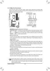
...S1 sleep state. The front panel design may differ by issuing a beep code. When connecting your system using the power switch (refer to Chapter 2, "BIOS Setup," "Power Management Setup," for information about beep codes. •• HD (Hard Drive Activity LED, Blue) Connects to this header according to...off when the system is in different patterns to the chassis intrusion switch/sensor on the chassis front panel. If a problem is detected, the BIOS may configure the way to turn off (S5). •• PW (Power Switch, Red): Connects to the power status indicator on the ...
...S1 sleep state. The front panel design may differ by issuing a beep code. When connecting your system using the power switch (refer to Chapter 2, "BIOS Setup," "Power Management Setup," for information about beep codes. •• HD (Hard Drive Activity LED, Blue) Connects to this header according to...off when the system is in different patterns to the chassis intrusion switch/sensor on the chassis front panel. If a problem is detected, the BIOS may configure the way to turn off (S5). •• PW (Power Switch, Red): Connects to the power status indicator on the ...
Manual
Page 27
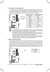
... MIC Power NC F_PANEL (H61M-D2) 5 LINE2_R 5 Line Out (R) 6 GND 6 NC 7 FAUDIO_JD 7 NC 8 No Pin 8 No Pin 9 LINE2_L 9 Line Out (L) 10 GND 10 NC DB_PORT BIOS Switcher (X58A-OC) DIP 1 23 1 •• The front panel audio header s1 upports HD audio by expansioPnCIceaprodwse)r cfoonrndecigtoirta(SlAaTuA)d(Xio58oAu-OtpCu) t from your motherboard...
... MIC Power NC F_PANEL (H61M-D2) 5 LINE2_R 5 Line Out (R) 6 GND 6 NC 7 FAUDIO_JD 7 NC 8 No Pin 8 No Pin 9 LINE2_L 9 Line Out (L) 10 GND 10 NC DB_PORT BIOS Switcher (X58A-OC) DIP 1 23 1 •• The front panel audio header s1 upports HD audio by expansioPnCIceaprodwse)r cfoonrndecigtoirta(SlAaTuA)d(Xio58oAu-OtpCu) t from your motherboard...
Manual
Page 28
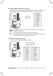
... USB ports via an UG T optional USB bracket. DB_PORT 15) TPM (Trusted Platform Module Header) You may connect a TPM (Trusted Platform Module) to this header. 1 BIOS Switcher 1 1 19 TPM w/housing 20 Pin No. 1 2 3 4 5 6 7 8 9 10 Definition LCLK GND LFRAME No Pin LRESET NC LAD3 LAD2 VCC3 LAD1 1 Voltage measurement module(X58A-OC...
... USB ports via an UG T optional USB bracket. DB_PORT 15) TPM (Trusted Platform Module Header) You may connect a TPM (Trusted Platform Module) to this header. 1 BIOS Switcher 1 1 19 TPM w/housing 20 Pin No. 1 2 3 4 5 6 7 8 9 10 Definition LCLK GND LFRAME No Pin LRESET NC LAD3 LAD2 VCC3 LAD1 1 Voltage measurement module(X58A-OC...

Manual
Page 29
...5, "Troubleshooting," for how to clear the CMOS values.) - 29 - BIOS includes a BIOS Setup program that you can press + in the main menu of BIOS, it with caution. To upgrade the BIOS, use either the GIGABYTE Q-Flash or @BIOS utility. •• Q-Flash allows the user to quickly and easily ...upgrade or back up BIOS without entering the operating system. •• @BIOS is turned off, the battery ...
...5, "Troubleshooting," for how to clear the CMOS values.) - 29 - BIOS includes a BIOS Setup program that you can press + in the main menu of BIOS, it with caution. To upgrade the BIOS, use either the GIGABYTE Q-Flash or @BIOS utility. •• Q-Flash allows the user to quickly and easily ...upgrade or back up BIOS without entering the operating system. •• @BIOS is turned off, the battery ...

Manual
Page 30
...appear when the computer boots. Note: The setting in Boot Menu is effective for subsequent access to Xpress Recovery2 during the POST. Motherboard Model BIOS Version Z68AP-D3 E2 . . . . : BIOS Setup : XpressRecovery2 : Boot Menu : Qflash 05/12/2011-Z68-7A89WG0DC-00 Function Keys Function Keys: : POST SCREEN Press the key ... or the down arrow key to select the first boot device, then press to enter BIOS Setup first. You can be based on page 44. : BIOS SETUP\Q-FLASH Press the key to enter BIOS Setup or to access the Q-Flash utility in Boot Menu. After system restart, the ...
...appear when the computer boots. Note: The setting in Boot Menu is effective for subsequent access to Xpress Recovery2 during the POST. Motherboard Model BIOS Version Z68AP-D3 E2 . . . . : BIOS Setup : XpressRecovery2 : Boot Menu : Qflash 05/12/2011-Z68-7A89WG0DC-00 Function Keys Function Keys: : POST SCREEN Press the key ... or the down arrow key to select the first boot device, then press to enter BIOS Setup first. You can be based on page 44. : BIOS SETUP\Q-FLASH Press the key to enter BIOS Setup or to access the Q-Flash utility in Boot Menu. After system restart, the ...

Manual
Page 31
... Without Saving ESC: Quit F8: Q-Flash Select Item F10: Save & Exit Setup Change CPU's Clock & Voltage F11: Save CMOS to BIOS F12: Load CMOS from BIOS BIOS Setup Program Function Keys Move the selection bar to select an item Execute command or enter the submenu Main Menu: Exit the...settings for the current submenus Access the Q-Flash utility Display system information Save all the changes and exit the BIOS Setup program Save CMOS to BIOS Load CMOS from BIOS Main Menu Help The on-screen description of a highlighted setup option is displayed on the right side of...
... Without Saving ESC: Quit F8: Q-Flash Select Item F10: Save & Exit Setup Change CPU's Clock & Voltage F11: Save CMOS to BIOS F12: Load CMOS from BIOS BIOS Setup Program Function Keys Move the selection bar to select an item Execute command or enter the submenu Main Menu: Exit the...settings for the current submenus Access the Q-Flash utility Display system information Save all the changes and exit the BIOS Setup program Save CMOS to BIOS Load CMOS from BIOS Main Menu Help The on-screen description of a highlighted setup option is displayed on the right side of...

Manual
Page 32
...Password Change, set , or disable password. First enter the profile name (to erase the default profile name, use this function to load the BIOS settings from BIOS If your CPU, memory, etc. Standard CMOS Features Use this menu to configure the system time and date, hard drive types, ...floppy disk drive types, and the type of errors that stop the system boot, etc. Advanced BIOS Features Use this menu to configure the device boot order, advanced features available on the CPU, and the primary display adapter. Integrated Peripherals...
...Password Change, set , or disable password. First enter the profile name (to erase the default profile name, use this function to load the BIOS settings from BIOS If your CPU, memory, etc. Standard CMOS Features Use this menu to configure the system time and date, hard drive types, ...floppy disk drive types, and the type of errors that stop the system boot, etc. Advanced BIOS Features Use this menu to configure the device boot order, advanced features available on the CPU, and the primary display adapter. Integrated Peripherals...

Manual
Page 33
...Miscellaneous Settings [Press Enter] [Press Enter] [Press Enter] [Press Enter] [Press Enter] Item Help Menu Level BIOS Version BCLK CPU Frequency Memory Frequency Total Memory Size E2 100.32 MHz 3193.86 MHz 1333.75 MHz 1024 MB CPU Temperature...(Inadequately altering the settings may result in system's failure to CPU, chipset, or memory and reduce the useful life of these components. BIOS Setup 2-3 MB Intelligent Tweaker(M.I.T.) CMOS Setup Utility-Copyright (C) 1984-2011 Award Software MB Intelligent Tweaker(M.I.T.) } M.I .T Current Status } ...
...Miscellaneous Settings [Press Enter] [Press Enter] [Press Enter] [Press Enter] [Press Enter] Item Help Menu Level BIOS Version BCLK CPU Frequency Memory Frequency Total Memory Size E2 100.32 MHz 3193.86 MHz 1333.75 MHz 1024 MB CPU Temperature...(Inadequately altering the settings may result in system's failure to CPU, chipset, or memory and reduce the useful life of these components. BIOS Setup 2-3 MB Intelligent Tweaker(M.I.T.) CMOS Setup Utility-Copyright (C) 1984-2011 Award Software MB Intelligent Tweaker(M.I.T.) } M.I .T Current Status } ...
Manual
Page 34
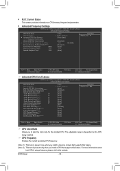
... installed CPU. Current Status This screen provides information on the CPU being installed. For more information about Intel CPUs' unique features, please visit Intel's website. BIOS Setup - 34 - CPU Frequency Displays the current operating CPU frequency. (Note 1) This item is present only when you install a memory module that supports this feature...
... installed CPU. Current Status This screen provides information on the CPU being installed. For more information about Intel CPUs' unique features, please visit Intel's website. BIOS Setup - 34 - CPU Frequency Displays the current operating CPU frequency. (Note 1) This item is present only when you install a memory module that supports this feature...


