User Manual
Page 1
GA-Z77X-UD5H User's Manual Rev. 1001 12ME-Z77XU5H-1001R
GA-Z77X-UD5H User's Manual Rev. 1001 12ME-Z77XU5H-1001R
User Manual
Page 2
Motherboard GA-Z77X-UD5H Feb. 24, 2012 Motherboard GA-Z77X-UD5H Feb. 24, 2012
Motherboard GA-Z77X-UD5H Feb. 24, 2012 Motherboard GA-Z77X-UD5H Feb. 24, 2012

User Manual
Page 4
Table of Contents Box Contents...6 Optional Items...6 GA-Z77X-UD5H Motherboard Layout 7 GA-Z77X-UD5H Motherboard Block Diagram 8 Chapter 1 Hardware Installation 9 1-1 Installation Precautions 9 1-2 Product Specifications 10 1-3 Installing the CPU and CPU Cooler 13 1-3-1 Installing the CPU 13 1-3-2 Installing the CPU ...
Table of Contents Box Contents...6 Optional Items...6 GA-Z77X-UD5H Motherboard Layout 7 GA-Z77X-UD5H Motherboard Block Diagram 8 Chapter 1 Hardware Installation 9 1-1 Installation Precautions 9 1-2 Product Specifications 10 1-3 Installing the CPU and CPU Cooler 13 1-3-1 Installing the CPU 13 1-3-2 Installing the CPU ...
User Manual
Page 6
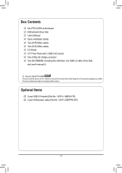
... notice. Optional Items †† 2-port USB 2.0 bracket (Part No. 12CR1-1UB030-5*R) †† 2-port SATA power cable (Part No. 12CF1-2SERPW-0*R) - 6 - Box Contents 55 GA-Z77X-UD5H motherboard 55 Motherboard driver disk 55 User's Manual 55 Quick Installation Guide 55 Two SATA 6Gb/s cables 55 Two SATA 3Gb/s cables 55 I/O Shield 55...
... notice. Optional Items †† 2-port USB 2.0 bracket (Part No. 12CR1-1UB030-5*R) †† 2-port SATA power cable (Part No. 12CF1-2SERPW-0*R) - 6 - Box Contents 55 GA-Z77X-UD5H motherboard 55 Motherboard driver disk 55 User's Manual 55 Quick Installation Guide 55 Two SATA 6Gb/s cables 55 Two SATA 3Gb/s cables 55 I/O Shield 55...
User Manual
Page 7
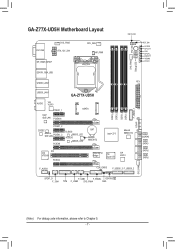
... PW_SW CMOS_SW RST_SW VCORE CPUVTT VSA CPUPLL DDRVTT VDIMM PCHIO SYS_FAN2 Debug LED (Note) ATX USB30_LAN1 AUDIO VIA VL810 PCIEX1_1 Intel® GbE LAN PCIEX16 GA-Z77X-UD5H mSATA PCIEX1_2 CODEC Atheros GbE LAN PCIEX1_3 PCIEX8 B_BIOS BBIOS_LED M_BIOS MBIOS_LED BAT Marvell 88SE9172 Intel® Z77 Marvell 88SE9172 VIA PCI VT6308 PCIEX4 PCIe...
... PW_SW CMOS_SW RST_SW VCORE CPUVTT VSA CPUPLL DDRVTT VDIMM PCHIO SYS_FAN2 Debug LED (Note) ATX USB30_LAN1 AUDIO VIA VL810 PCIEX1_1 Intel® GbE LAN PCIEX16 GA-Z77X-UD5H mSATA PCIEX1_2 CODEC Atheros GbE LAN PCIEX1_3 PCIEX8 B_BIOS BBIOS_LED M_BIOS MBIOS_LED BAT Marvell 88SE9172 Intel® Z77 Marvell 88SE9172 VIA PCI VT6308 PCIEX4 PCIe...
User Manual
Page 8
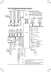
GA-Z77X-UD5H Motherboard Block Diagram 2 PCI Express x8 1 PCI Express x16 2 PCI Express x4+1 PCI Express x8 CPU CLK+/- (100 MHz) PCIe CLK (100 MHz) or or ...
GA-Z77X-UD5H Motherboard Block Diagram 2 PCI Express x8 1 PCI Express x16 2 PCI Express x4+1 PCI Express x8 CPU CLK+/- (100 MHz) PCIe CLK (100 MHz) or or ...
User Manual
Page 30
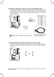
...supports a single SATA device. G.QBOFMPin No. The Marvell 88SE9172 chip supports RAID 0 and RAID 1. ACPI_CPT (GA-IVB) SMB_CPT (GA-IVB) CLR_CMOS CI DIS_ME GP15_CPT (GA-IVB) XDP_CPU XDP_PCH (GA-IVB) F_PANEL (H61M-D2) mSATA PWM Switch (X58A-OC) BIOS Switcher (X58A-OC) 1 M_SATA F_PANEL(NH... will become unavailable. Definition GSATA3 1 GND 2 TXP 7 17 3 TXN 7 16 4 GND 5 RXN 6 RXP 7 GND 7 1 GSATA3 8 BIOS_PH (GA-IVB) A RAID 0 or RAID 1 configuration requires two hard drives. Refer to Chapter 5, "Configuring SATA Hard Drive(s)," for instructions on configuring a RAID array...
...supports a single SATA device. G.QBOFMPin No. The Marvell 88SE9172 chip supports RAID 0 and RAID 1. ACPI_CPT (GA-IVB) SMB_CPT (GA-IVB) CLR_CMOS CI DIS_ME GP15_CPT (GA-IVB) XDP_CPU XDP_PCH (GA-IVB) F_PANEL (H61M-D2) mSATA PWM Switch (X58A-OC) BIOS Switcher (X58A-OC) 1 M_SATA F_PANEL(NH... will become unavailable. Definition GSATA3 1 GND 2 TXP 7 17 3 TXN 7 16 4 GND 5 RXN 6 RXP 7 GND 7 1 GSATA3 8 BIOS_PH (GA-IVB) A RAID 0 or RAID 1 configuration requires two hard drives. Refer to Chapter 5, "Configuring SATA Hard Drive(s)," for instructions on configuring a RAID array...

User Manual
Page 32
... Front Panel Audio: Pin No. If your expansion card. Incorrect connection between the module connector and the motherboard header will be present on each wire (GA-IVB) instead of a single plug. Definition 9 1 1 MIC2_L 1 MIC F_AUDIO(H) F2_PANELG(NNHD) 3 MIC2_R 2 GND 3 MIC Power F_PANEL (H61M..."Configuring 2/4/5.1/7.1-Channel Audio." Definition oltage measurement points(G1.Sniper 3) BIOS Switcher (SW4) 1 1 SPDIFO 2 GND XDP_CPU XDP_PCH (GA-IVB) Hardware Installation - 32 - Make sure the wire assignments of the module connector match the pin assignments of the front ...
... Front Panel Audio: Pin No. If your expansion card. Incorrect connection between the module connector and the motherboard header will be present on each wire (GA-IVB) instead of a single plug. Definition 9 1 1 MIC2_L 1 MIC F_AUDIO(H) F2_PANELG(NNHD) 3 MIC2_R 2 GND 3 MIC Power F_PANEL (H61M..."Configuring 2/4/5.1/7.1-Channel Audio." Definition oltage measurement points(G1.Sniper 3) BIOS Switcher (SW4) 1 1 SPDIFO 2 GND XDP_CPU XDP_PCH (GA-IVB) Hardware Installation - 32 - Make sure the wire assignments of the module connector match the pin assignments of the front ...


