Manual
Page 3
GS-R22T61-RH/GS-R22T81-RH Rack Mount Server Table of Contents Preface...2 Safety, Care and Regulatory Information 5 System Specification 9 System Hardware Installation 11 Chassis Removal and Installation 12 CPU Installation ...13 Heat Sink Installation ...14 Memory Installation ...15 PCI Expansion Card Installation (GC-RLE2N-RH/GC-RFE2N-RH 18 PCI Expansion Card Installation (GC-RFX2N-RH/Optional 20 GS-R22T81-RH Hard Disk Drive Installation 22 GS-R22T61-RH Hard Disk Drive Installation 23 FAN Duct Removal and Installation 24 Appearance of GS-R22T61-RH/GS-R22T81-RH 25 Front View of GS-...
GS-R22T61-RH/GS-R22T81-RH Rack Mount Server Table of Contents Preface...2 Safety, Care and Regulatory Information 5 System Specification 9 System Hardware Installation 11 Chassis Removal and Installation 12 CPU Installation ...13 Heat Sink Installation ...14 Memory Installation ...15 PCI Expansion Card Installation (GC-RLE2N-RH/GC-RFE2N-RH 18 PCI Expansion Card Installation (GC-RFX2N-RH/Optional 20 GS-R22T81-RH Hard Disk Drive Installation 22 GS-R22T61-RH Hard Disk Drive Installation 23 FAN Duct Removal and Installation 24 Appearance of GS-R22T61-RH/GS-R22T81-RH 25 Front View of GS-...
Manual
Page 5
... national electrical codes. This is used in the product's documentation. * Only authorized service technicians should repair laser devices. Precaution for Product with Modems, Telecommunications, ot Local Area Network Options Observe the following guidelines when working with options: * Do not connect or use . * The product should be accessible at all times because it is a safety feature. GS-R22T61-RH/GS-R22T81-RH Rack Mount Server Safety...
... national electrical codes. This is used in the product's documentation. * Only authorized service technicians should repair laser devices. Precaution for Product with Modems, Telecommunications, ot Local Area Network Options Observe the following guidelines when working with options: * Do not connect or use . * The product should be accessible at all times because it is a safety feature. GS-R22T61-RH/GS-R22T81-RH Rack Mount Server Safety...
Manual
Page 6
... or telephone cable into the network interface controller (NIC) receptacle. * Disconnect the modem cable before opening a product enclosure, touching or installing internal components, or touching an uninsulated modem cable or jack. * Do not use a telephone line to report a gas leak while you will be used in accordance with the instruction manual, may be required to take adequate measures. In a domestic environment this information to operate the...
... or telephone cable into the network interface controller (NIC) receptacle. * Disconnect the modem cable before opening a product enclosure, touching or installing internal components, or touching an uninsulated modem cable or jack. * Do not use a telephone line to report a gas leak while you will be used in accordance with the instruction manual, may be required to take adequate measures. In a domestic environment this information to operate the...
Manual
Page 7
GS-R22T61-RH/GS-R22T81-RH Rack Mount Server the FCC. Your telephone company may make such connections themselves, but should contact the appropriate electric inspection authority, or electrician, as set out in the radio interference regulations of service in its facilities, equipment, operations, or procedures that compliance with an Industry Canada-compliant modem) The Canadian Department of your equipment. This...
GS-R22T61-RH/GS-R22T81-RH Rack Mount Server the FCC. Your telephone company may make such connections themselves, but should contact the appropriate electric inspection authority, or electrician, as set out in the radio interference regulations of service in its facilities, equipment, operations, or procedures that compliance with an Industry Canada-compliant modem) The Canadian Department of your equipment. This...
Manual
Page 10
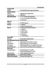
...x VGA port 2 x USB 2.0 dual-port connector Rear I/O P/S 2 Keyboard and Mouse Connectors 1 x Serial port 4 x USB 2.0 ports 1 x VGA connector 2 x GLAN ports 1 x 10/100 LAN port System BIOS: BIOS Type Phoenix BIOS on 8Mb flash ROM Server Management Functions: (Optional device) BMC Chip Server Engines POLIT 2 IPMI 2.0 controller Failure Detection IPMI 2.0 specification of Server management Event Logging 32KB Nonvolatile Memory to Log System Failure Events Remote Management ...
...x VGA port 2 x USB 2.0 dual-port connector Rear I/O P/S 2 Keyboard and Mouse Connectors 1 x Serial port 4 x USB 2.0 ports 1 x VGA connector 2 x GLAN ports 1 x 10/100 LAN port System BIOS: BIOS Type Phoenix BIOS on 8Mb flash ROM Server Management Functions: (Optional device) BMC Chip Server Engines POLIT 2 IPMI 2.0 controller Failure Detection IPMI 2.0 specification of Server management Event Logging 32KB Nonvolatile Memory to Log System Failure Events Remote Management ...
Manual
Page 11
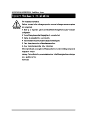
... sections unless you remove or replace any hardware configuration. 2. GS-R22T61-RH/GS-R22T81-RH Rack Mount Server System Hardware Installation Pre-installation Instructions Perform the steps below before you open the server or before performing any component. 1. Unplug all the peripherals connected to it. 3. Place the system unit on a flat and stable surface. 6. Back up all telecommunication cables from the power outlets. 4. Turn off the server before you start installing components may...
... sections unless you remove or replace any hardware configuration. 2. GS-R22T61-RH/GS-R22T81-RH Rack Mount Server System Hardware Installation Pre-installation Instructions Perform the steps below before you open the server or before performing any component. 1. Unplug all the peripherals connected to it. 3. Place the system unit on a flat and stable surface. 6. Back up all telecommunication cables from the power outlets. 4. Turn off the server before you start installing components may...
Manual
Page 39
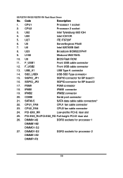
Code Description 1. U190 Winbond W83792G 10. F_USB2 Front USB cable connector 13. SGPIO_JP2 SGPIO connector for processor 2 DIMME1-E2 DIMMF1-F2 39 DIMMD1-D2 DDR3 sockets for BP board 2 17. GS-R22T61-RH/GS-R22T81-RH Rack Mount Server No. U82 Intel Tylersburg-36D IOH 4. U8 BIOS Flash ROM 11. U60 Intel ICH10R 5. USB_A1 USB Type A connector 14. PSMI1 PSMI connector 18. IPMB2 IPMB2 connector 20. CPU1 Processor 1 socket 2. CPU2 Processor 2 socket 3. U27 ITE...
Code Description 1. U190 Winbond W83792G 10. F_USB2 Front USB cable connector 13. SGPIO_JP2 SGPIO connector for processor 2 DIMME1-E2 DIMMF1-F2 39 DIMMD1-D2 DDR3 sockets for BP board 2 17. GS-R22T61-RH/GS-R22T81-RH Rack Mount Server No. U82 Intel Tylersburg-36D IOH 4. U8 BIOS Flash ROM 11. U60 Intel ICH10R 5. USB_A1 USB Type A connector 14. PSMI1 PSMI connector 18. IPMB2 IPMB2 connector 20. CPU1 Processor 1 socket 2. CPU2 Processor 2 socket 3. U27 ITE...
Manual
Page 47
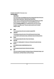
... the items of Phoenix BIOS special enhanced features. (ex: Auto detect fan and temperature status, automatically configure hard disk parameters.) Power This setup page includes all the items of Green function features. Security Change, set, or disable password. This action makes the system reset to the default settings for the highlighted item. To exit the Help Window press . It allows you to use and the possible selections...
... the items of Phoenix BIOS special enhanced features. (ex: Auto detect fan and temperature status, automatically configure hard disk parameters.) Power This setup page includes all the items of Green function features. Security Change, set, or disable password. This action makes the system reset to the default settings for the highlighted item. To exit the Help Window press . It allows you to use and the possible selections...
Manual
Page 62
.... (Default setting) Intel (R) I/OAT Enabled Enable configuration mapped accesses to reduce the MTRR occupation. 512MB Select 512MB as granularity of PCI hole. 1GB Select 1GB as granularity of PCI hole. (Default setting) 2GB Select 2GB as granularity of PCI hole for Port1~Port 10. Coherency Support Enabled Enable Coherency Support. VT-d for Port1~Port 10 Enabled Enable VT-d support for Port 1~Port 10 ports through ATSR structures in ACPI Tables. (Default setting) Disabled Disable VT-d for PCI resource. BIOS Setup...
.... (Default setting) Intel (R) I/OAT Enabled Enable configuration mapped accesses to reduce the MTRR occupation. 512MB Select 512MB as granularity of PCI hole. 1GB Select 1GB as granularity of PCI hole. (Default setting) 2GB Select 2GB as granularity of PCI hole for Port1~Port 10. Coherency Support Enabled Enable Coherency Support. VT-d for Port1~Port 10 Enabled Enable VT-d support for Port 1~Port 10 ports through ATSR structures in ACPI Tables. (Default setting) Disabled Disable VT-d for PCI resource. BIOS Setup...
Manual
Page 64
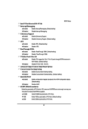
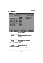
Onboard LAN iSCSI Boot ROM Enabled Enable Onboard LAN iSCSI Boot ROM. Disabled Disable this function. (Defualt setting) Onboard LAN1 Controller Enabled Enable Onboard LAN controller. (Defualt setting) Disabled Disable this function. PCI Configuration BIOS Setup Figure 2-4: PCI Configuration PCI Slot 1/2/3/4/5 Option ROM Enabled Enable this item to initialize device expansion ROM. (Defualt setting) Disabled Disable this function. 64 Onboard VGA Controller Enabled Enable Onboard VGA device. (Defualt setting) Disabled Disable this function.
Onboard LAN iSCSI Boot ROM Enabled Enable Onboard LAN iSCSI Boot ROM. Disabled Disable this function. (Defualt setting) Onboard LAN1 Controller Enabled Enable Onboard LAN controller. (Defualt setting) Disabled Disable this function. PCI Configuration BIOS Setup Figure 2-4: PCI Configuration PCI Slot 1/2/3/4/5 Option ROM Enabled Enable this item to initialize device expansion ROM. (Defualt setting) Disabled Disable this function. 64 Onboard VGA Controller Enabled Enable Onboard VGA device. (Defualt setting) Disabled Disable this function.
Manual
Page 65
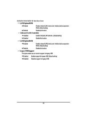
Enabled Enables support for legacy USB (Default setting) Disabled Disables support for legacy USB. GS-R22T61-RH/GS-R22T81-RH Rack Mount Server LAN1Option ROM Enabled Enable onboard LAN1 device and initialize device expansion ROM. (Default setting) Disabled Disable this function. Onboard LAN2 Controller Enabled Enable Onboard LAN controller. (Defualt setting) Disabled Disable this function. LAN2Option ROM Enabled Disabled Enable onboard LAN2 device and initialize device expansion ROM. (Default setting) Disable this function. Legacy USB Support This option allows user to ...
Enabled Enables support for legacy USB (Default setting) Disabled Disables support for legacy USB. GS-R22T61-RH/GS-R22T81-RH Rack Mount Server LAN1Option ROM Enabled Enable onboard LAN1 device and initialize device expansion ROM. (Default setting) Disabled Disable this function. Onboard LAN2 Controller Enabled Enable Onboard LAN controller. (Defualt setting) Disabled Disable this function. LAN2Option ROM Enabled Disabled Enable onboard LAN2 device and initialize device expansion ROM. (Default setting) Disable this function. Legacy USB Support This option allows user to ...
Manual
Page 67
... function. (Default setting) SATA Port 0/1/2/3/4/5 The category identifies the types of Serial SATA hard disk from drive 0 to enable SATA AHCI function for Serial ATA function. System will not work in Legacy mode. Hard drive information should be labled on -board serial ATA function. GS-R22T61-RH/GS-R22T81-RH Rack Mount Server Serial ATA Enabled Disabled Enables on-board serial ATA function. (Default setting) Disables on the outside device casing. SATA RAID Enable Enabled Disabled Enabled SATA RAID function. Disabled this category. Note that has been installed in the...
... function. (Default setting) SATA Port 0/1/2/3/4/5 The category identifies the types of Serial SATA hard disk from drive 0 to enable SATA AHCI function for Serial ATA function. System will not work in Legacy mode. Hard drive information should be labled on -board serial ATA function. GS-R22T61-RH/GS-R22T81-RH Rack Mount Server Serial ATA Enabled Disabled Enables on-board serial ATA function. (Default setting) Disables on the outside device casing. SATA RAID Enable Enabled Disabled Enabled SATA RAID function. Disabled this category. Note that has been installed in the...
Manual
Page 69
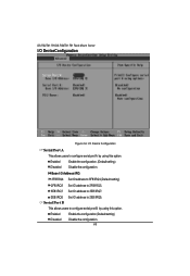
...configuration (Default setting) Disable the configuration. 69 Serial Port B This allows users to configure serial prot B by using this option. Base I /O Device Configuration Serial Port A This allows users to configure serial prot A by using this option. GS-R22T61-RH/GS-R22T81-RH Rack Mount Server I/O DeviceConfiguration Figure 2-6: I /O Address/IRQ 3F8/IRQ4 Set IO address to 3F8/IRQ4.(Default setting) 2F8/IRQ3 Set IO address to 2F8/IRQ3. 3E8/IRQ7 Set IO address to 3E8/IRQ7. 2E8/IRQ5 Set IO address to 2E8/IRQ5. Enabled Disabled Enable the configuration. (Default setting) Disable...
...configuration (Default setting) Disable the configuration. 69 Serial Port B This allows users to configure serial prot B by using this option. Base I /O Device Configuration Serial Port A This allows users to configure serial prot A by using this option. GS-R22T61-RH/GS-R22T81-RH Rack Mount Server I/O DeviceConfiguration Figure 2-6: I /O Address/IRQ 3F8/IRQ4 Set IO address to 3F8/IRQ4.(Default setting) 2F8/IRQ3 Set IO address to 2F8/IRQ3. 3E8/IRQ7 Set IO address to 3E8/IRQ7. 2E8/IRQ5 Set IO address to 2E8/IRQ5. Enabled Disabled Enable the configuration. (Default setting) Disable...
Manual
Page 92
... Restore CPU control word during warm boot Initialize PCI Bus Mastering devices Initialize keyboard controller BIOS ROM checksum Initialize cache before memory autosize 8254 timer initialization 8237 DMA controller initialization Reset Programmable Interrupt Controller Test DRAM refresh Test 8742 Keyboard Controller Set ES segment register to 4 GB Enable A20 line Autosize DRAM Initialize POST Memory Manager Clear 512 KB base RAM RAM failure on address line xxxx* RAM failure on data bits xxxx* of low byte of memory bus Enable...
... Restore CPU control word during warm boot Initialize PCI Bus Mastering devices Initialize keyboard controller BIOS ROM checksum Initialize cache before memory autosize 8254 timer initialization 8237 DMA controller initialization Reset Programmable Interrupt Controller Test DRAM refresh Test 8742 Keyboard Controller Set ES segment register to 4 GB Enable A20 line Autosize DRAM Initialize POST Memory Manager Clear 512 KB base RAM RAM failure on address line xxxx* RAM failure on data bits xxxx* of low byte of memory bus Enable...
Manual
Page 93
... Test extended memory Test extended memory address lines Jump to UserPatch1 Configure advanced cache registers Initialize Multi Processor APIC Enable external and CPU caches Setup System Management Mode (SMM) area Display external L2 cache size Load custom defaults (optional) Display shadow-area message Display possible high address for UMB recovery Display error messages Check for configuration errors Check for keyboard errors Set up hardware interrupt vectors Initialize coprocessor if present Disable onboard Super I/O ports and IRQs Late POST device initialization Detect and install external...
... Test extended memory Test extended memory address lines Jump to UserPatch1 Configure advanced cache registers Initialize Multi Processor APIC Enable external and CPU caches Setup System Management Mode (SMM) area Display external L2 cache size Load custom defaults (optional) Display shadow-area message Display possible high address for UMB recovery Display error messages Check for configuration errors Check for keyboard errors Set up hardware interrupt vectors Initialize coprocessor if present Disable onboard Super I/O ports and IRQs Late POST device initialization Detect and install external...
Manual
Page 94
... Enter SETUP Clear Boot flag Check for errors POST done - prepare to UserPatch2 Build MPTABLE for multi-processor boards Install CD ROM for boot Clear huge ES segment register Fixup Multi Processor table Search for option ROMs. One long, two short beeps on checksum failure Check for SMART Drive (optional) Shadow option ROMs Set up Power Management Initialize security engine (optional) Enable hardware interrupts Determine number of ATA and SCSI drives Set time of ATA drives (optional) Initialize hard-disk controllers Initialize local-bus hard-disk controllers...
... Enter SETUP Clear Boot flag Check for errors POST done - prepare to UserPatch2 Build MPTABLE for multi-processor boards Install CD ROM for boot Clear huge ES segment register Fixup Multi Processor table Search for option ROMs. One long, two short beeps on checksum failure Check for SMART Drive (optional) Shadow option ROMs Set up Power Management Initialize security engine (optional) Enable hardware interrupts Determine number of ATA and SCSI drives Set time of ATA drives (optional) Initialize hard-disk controllers Initialize local-bus hard-disk controllers...
Manual
Page 95
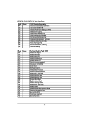
... F7h Beeps 1 For Boot Block in Flash ROM Initialize the chipset Initialize the bridge Initialize the CPU Initialize system timer Initialize system I/O Check force recovery boot Checksum BIOS ROM Go to BIOS Set Huge Segment Initialize Multi Processor Initialize OEM special code Initialize PIC and DMA Initialize Memory type Initialize Memory size Shadow Boot Block System memory test Initialize interrupt vectors Initialize Run Time Clock Initialize video Initialize System Management Mode Output one beep before boot Boot...
... F7h Beeps 1 For Boot Block in Flash ROM Initialize the chipset Initialize the bridge Initialize the CPU Initialize system timer Initialize system I/O Check force recovery boot Checksum BIOS ROM Go to BIOS Set Huge Segment Initialize Multi Processor Initialize OEM special code Initialize PIC and DMA Initialize Memory type Initialize Memory size Shadow Boot Block System memory test Initialize interrupt vectors Initialize Run Time Clock Initialize video Initialize System Management Mode Output one beep before boot Boot...
Manual
Page 96
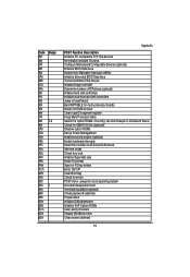
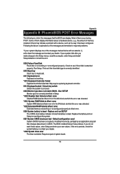
... configured. May require replacing keyboard controller. 0213 Keyboard locked - Replace the battery and run SETUP The CMOS clock battery indicator shows the battery is dead. Run SETUP Monitor type not correctly identified in the 64k block at which the error was detected. *0231 System RAM Failed at offset: nnnn System RAM failed at offset: nnnn Extended memory not working . *0212 Keyboard Controller Failed Keyboard controller failed test. Appexdix Appexdix B PhoenixBIOS POST Error Messages List The following is a list of system board...
... configured. May require replacing keyboard controller. 0213 Keyboard locked - Replace the battery and run SETUP The CMOS clock battery indicator shows the battery is dead. Run SETUP Monitor type not correctly identified in the 64k block at which the error was detected. *0231 System RAM Failed at offset: nnnn System RAM failed at offset: nnnn Extended memory not working . *0212 Keyboard Controller Failed Keyboard controller failed test. Appexdix Appexdix B PhoenixBIOS POST Error Messages List The following is a list of system board...
Manual
Page 97
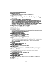
... specified device. GS-R22T61-RH/GS-R22T81-RH Rack Mount Server *0270 Real time clock error Real-Time Clock fails BIOS hardware test. May require setting legal date (1991-2099). 0280 Previous boot incomplete - Default configuration used Previous POST did not complete successfully. On systems with the proper diskette type in Setup. 02D0 System cache error - Cache disabled RAM cache failed and BIOS disabled the cache. Allocation Error for: device Run ISA or EISA Configuration Utility to replace the cache. CD ROM Drive CD ROM Drive...
... specified device. GS-R22T61-RH/GS-R22T81-RH Rack Mount Server *0270 Real time clock error Real-Time Clock fails BIOS hardware test. May require setting legal date (1991-2099). 0280 Previous boot incomplete - Default configuration used Previous POST did not complete successfully. On systems with the proper diskette type in Setup. 02D0 System cache error - Cache disabled RAM cache failed and BIOS disabled the cache. Allocation Error for: device Run ISA or EISA Configuration Utility to replace the cache. CD ROM Drive CD ROM Drive...
Manual
Page 98
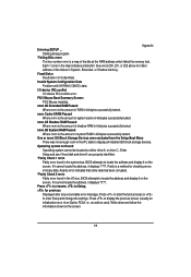
... drive C:. Invalid System Configuration Data Problem with NVRAM (CMOS) data. One or more I2O Block Storage Devices were excluded from the Setup Boot Menu There was not enough room in kilobytes successfully tested. See errors 230, 231, or 232 above for checking errors in kilobytes successfully tested. nnnn Cache SRAM Passed Where nnnn is the amount of an Option ROM, i.e., an add-on card). Operating system not found in kilobytes successfully tested. BIOS...
... drive C:. Invalid System Configuration Data Problem with NVRAM (CMOS) data. One or more I2O Block Storage Devices were excluded from the Setup Boot Menu There was not enough room in kilobytes successfully tested. See errors 230, 231, or 232 above for checking errors in kilobytes successfully tested. nnnn Cache SRAM Passed Where nnnn is the amount of an Option ROM, i.e., an add-on card). Operating system not found in kilobytes successfully tested. BIOS...