User Manual
Page 2
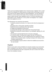
...by the warranty: 1. Be sure to your devices. website. (http://www.gigabyte.com.tw) The following are not detached from the casing prior to transportation of casing water/air-cooling solution technology to the casing or other computer-related devices. 9. English Thank you for thermal dissipation. ...manner other objects due to other than the designed purpose. 2. The five features of 3D Mercury series casing include state-of the "3D Mercury" series, please visit Gigabyte Tech. For further information and specifications of -the-art design, built-in the installation manual. 2 ...
...by the warranty: 1. Be sure to your devices. website. (http://www.gigabyte.com.tw) The following are not detached from the casing prior to transportation of casing water/air-cooling solution technology to the casing or other computer-related devices. 9. English Thank you for thermal dissipation. ...manner other objects due to other than the designed purpose. 2. The five features of 3D Mercury series casing include state-of the "3D Mercury" series, please visit Gigabyte Tech. For further information and specifications of -the-art design, built-in the installation manual. 2 ...
User Manual
Page 3
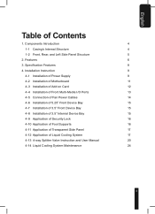
... of Security Lock 16 4-10 Application of Foot Supports 16 4-11 Application of Transparent Side Panel 17 4-12 Application of Contents 1. Specification Features 8 4. Components Introduction 4 1-1 Casing's Internal Structure 4 1-2 Front, Rear, and Left Side Panel Structure 5 2. English Table of Liquid Cooling System 17 4-13 4-way Splitter Valve Instruction and User Manual 20...
... of Security Lock 16 4-10 Application of Foot Supports 16 4-11 Application of Transparent Side Panel 17 4-12 Application of Contents 1. Specification Features 8 4. Components Introduction 4 1-1 Casing's Internal Structure 4 1-2 Front, Rear, and Left Side Panel Structure 5 2. English Table of Liquid Cooling System 17 4-13 4-way Splitter Valve Instruction and User Manual 20...

User Manual
Page 4
... off x 12 b. Extended screw for securing power sup- 4 ply retainer plate. Extended power supply retainer plate. Power Supply Bay 2. AM2 Water block bracket i. Key x 2 e. English 1. Gigabyte Liquid Coolant x 2 Power Extension Cable x 2 c. 3.5" device Securing Runner x 10 d. Tool Enclosure 5 2 3 6 8 7 a. Wire clamp x 2 f. k. Components Introduction...
... off x 12 b. Extended screw for securing power sup- 4 ply retainer plate. Extended power supply retainer plate. Power Supply Bay 2. AM2 Water block bracket i. Key x 2 e. English 1. Gigabyte Liquid Coolant x 2 Power Extension Cable x 2 c. 3.5" device Securing Runner x 10 d. Tool Enclosure 5 2 3 6 8 7 a. Wire clamp x 2 f. k. Components Introduction...
User Manual
Page 6
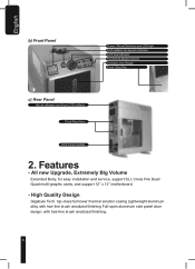
High Quality Design Gigabyte Tech. All new Upgrade, Extremely Big Volume Extended Body, for easy installation and service, support SLI, Cross Fire Dual/ Quad multi-graphic cards, and support ... Front 12cm Fan c) Rear Panel Hot air release vent from LCS radiator Dual Rear fans LCS Tube Outlets 2. Features - top-class full tower thermal solution casing Lightweight aluminum alloy with hair-line brush anodized finishing Full-open aluminum side panel door design, with hair-line brush anodized finishing. 6
High Quality Design Gigabyte Tech. All new Upgrade, Extremely Big Volume Extended Body, for easy installation and service, support SLI, Cross Fire Dual/ Quad multi-graphic cards, and support ... Front 12cm Fan c) Rear Panel Hot air release vent from LCS radiator Dual Rear fans LCS Tube Outlets 2. Features - top-class full tower thermal solution casing Lightweight aluminum alloy with hair-line brush anodized finishing Full-open aluminum side panel door design, with hair-line brush anodized finishing. 6

User Manual
Page 12
... insert the stand offs. Motherboard ATX Mini ATX Micro ATX E-ATX Motherboard screws 9 9 9 12 Code name A1-A9 M1-M9 U1-U9 E1-E12 Case copper post 9 9 9 12 4-3 Installation of Add on cards such as graphics cards and network cards. English 4-2-2 If the motherboard is an LGA775, ...please use the back plate and stick it behind the motherboard. 4-2-5 Use the motherboard screws to secure the motherboard onto the back wall of the case (refer to your motherboard manual to check what type of motherboard you have). 4-2-3 According to become faulty or damaged. 4-2-4 Install the motherboard I/O ...
... insert the stand offs. Motherboard ATX Mini ATX Micro ATX E-ATX Motherboard screws 9 9 9 12 Code name A1-A9 M1-M9 U1-U9 E1-E12 Case copper post 9 9 9 12 4-3 Installation of Add on cards such as graphics cards and network cards. English 4-2-2 If the motherboard is an LGA775, ...please use the back plate and stick it behind the motherboard. 4-2-5 Use the motherboard screws to secure the motherboard onto the back wall of the case (refer to your motherboard manual to check what type of motherboard you have). 4-2-3 According to become faulty or damaged. 4-2-4 Install the motherboard I/O ...

User Manual
Page 13
... causes faults will void your warranty The front panel includes (1) 4 x USB 2.0, 1 x IEEE 1394 and HD or AC'97 audio jack (depending on the motherboard) (2) Basic casing power switch control cable kit Required Tools: None 4-4-1 Insert the USB 2.0 connectors into the corresponding socket on the motherboard (please refer to the motherboard user...
... causes faults will void your warranty The front panel includes (1) 4 x USB 2.0, 1 x IEEE 1394 and HD or AC'97 audio jack (depending on the motherboard) (2) Basic casing power switch control cable kit Required Tools: None 4-4-1 Insert the USB 2.0 connectors into the corresponding socket on the motherboard (please refer to the motherboard user...

User Manual
Page 14
...Definition Pin Definition 1 MIC 6 NC 2 GND 7 NC 3 MIC Power 8 NO Pin 4 NC 9 Line Out(L) 5 Line Out(R) 10 NC 4-4-4 Basic casing power switch control cable kit. board. LED Brown (+)/White (-) 4-4-5 Power switch connector, LCS power supply (including LCS emergency shutdown). Please read the motherboard user manual... Definition 1 MIC2_L 6 FSENSE1 2 GND 7 FAUDIO_JD 3 MIC2_R 8 No Pin 4 -ACZ_DET 9 LINE2_L 5 LINE2_R 10 FSENSE2 Required Tools: None This case includes internal connectors that connect the front and rear fans, making it a 3-pin power connector.
...Definition Pin Definition 1 MIC 6 NC 2 GND 7 NC 3 MIC Power 8 NO Pin 4 NC 9 Line Out(L) 5 Line Out(R) 10 NC 4-4-4 Basic casing power switch control cable kit. board. LED Brown (+)/White (-) 4-4-5 Power switch connector, LCS power supply (including LCS emergency shutdown). Please read the motherboard user manual... Definition 1 MIC2_L 6 FSENSE1 2 GND 7 FAUDIO_JD 3 MIC2_R 8 No Pin 4 -ACZ_DET 9 LINE2_L 5 LINE2_R 10 FSENSE2 Required Tools: None This case includes internal connectors that connect the front and rear fans, making it a 3-pin power connector.
User Manual
Page 15
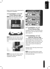
... 3D Mercury provides built-in bays to accommodate up to complete the installation 4-6 Installation of 5.25" Front Device Bay 4-6-1 Open the side panel of the case and remove the mesh drive rail and metal EMI plate of the chassis. The built-in HDD requires securing runners which can be found in...
... 3D Mercury provides built-in bays to accommodate up to complete the installation 4-6 Installation of 5.25" Front Device Bay 4-6-1 Open the side panel of the case and remove the mesh drive rail and metal EMI plate of the chassis. The built-in HDD requires securing runners which can be found in...
User Manual
Page 16
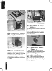
... lock and rotate it 90 degrees according to the diagram to prevent bending of the foot supports. 16 Note: When moving or laying down the case, please swivel the foot support to the closed position to lock and unlock it according to open or retract. Connect it . 4-8-3 In... case the length of the power cable is not sufficient for ensuring the casing is firmly seated on the side panel. English 4-8-2 For installation of the 4th and 5th HDDs, remove the tool...
... lock and rotate it 90 degrees according to the diagram to prevent bending of the foot supports. 16 Note: When moving or laying down the case, please swivel the foot support to the closed position to lock and unlock it according to open or retract. Connect it . 4-8-3 In... case the length of the power cable is not sufficient for ensuring the casing is firmly seated on the side panel. English 4-8-2 For installation of the 4th and 5th HDDs, remove the tool...