User Manual
Page 2
...). 7. The devices inside, including power supply, hard disk, CD-ROM drive, motherboard, ventilator, etc, are not covered by the warranty 1. Incorrect connector installation may cause damage to personnel and devices. The internal cable management and tool-free design provide users with changeable LED colors (blue/white) and the see-through/air inlet side panel, users can customize their own style...
...). 7. The devices inside, including power supply, hard disk, CD-ROM drive, motherboard, ventilator, etc, are not covered by the warranty 1. Incorrect connector installation may cause damage to personnel and devices. The internal cable management and tool-free design provide users with changeable LED colors (blue/white) and the see-through/air inlet side panel, users can customize their own style...
User Manual
Page 3
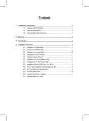
...;cation ...8 4 Installation Instruction ...9 4-1 Installation of Power Supply 9 4-2 Installation of Motherboard 9 4-3 Installation of Interface Card 10 4-4 Installation of Front I/O Panel 11 4-5 Chassis's Internal Structure 12 4-6 Installation of 5.25" Front Device Bay 13 4-7 Installation of 3.5" Front Device Bay 13 4-8 Installation of Built-in HDD (Hard Disc Drive 14 4-9 Power cable installation of the front projector light 14 4-10 DIY Front Bracket of Projector Light 15 4-11 Foot Stand Instruction 16 4-12 Liquid Cooling System Support 17 4-13...
...;cation ...8 4 Installation Instruction ...9 4-1 Installation of Power Supply 9 4-2 Installation of Motherboard 9 4-3 Installation of Interface Card 10 4-4 Installation of Front I/O Panel 11 4-5 Chassis's Internal Structure 12 4-6 Installation of 5.25" Front Device Bay 13 4-7 Installation of 3.5" Front Device Bay 13 4-8 Installation of Built-in HDD (Hard Disc Drive 14 4-9 Power cable installation of the front projector light 14 4-10 DIY Front Bracket of Projector Light 15 4-11 Foot Stand Instruction 16 4-12 Liquid Cooling System Support 17 4-13...

User Manual
Page 4
English English English 1 Components Introduction 1-1 Chassis's Internal Structure 1 4 3 2 8 1 Power supply 5 6 7 2 PCI tool-free fastener 3 Motherboard/panel card 4 5.25" Front device bay English Deutsch Deutsch English 4
English English English 1 Components Introduction 1-1 Chassis's Internal Structure 1 4 3 2 8 1 Power supply 5 6 7 2 PCI tool-free fastener 3 Motherboard/panel card 4 5.25" Front device bay English Deutsch Deutsch English 4
User Manual
Page 5
... transparent projector panel x 1 (Equipped with Poseidon at shipment) a.USB 2.0 b. Motherboard securing screw x 9 d. Basic chassis power front projector light front and rear fans switch control cable kit 5 English English 5 3.5" Floppy 6 Build-in hard disk English English English Deutsch Deutsch 7 Accessory box (Refer to the right figures for the attachments in the tool enclosure) 8 Front cable kit a. Standoff x 9 b. Power supply of f. Power supply of...
... transparent projector panel x 1 (Equipped with Poseidon at shipment) a.USB 2.0 b. Motherboard securing screw x 9 d. Basic chassis power front projector light front and rear fans switch control cable kit 5 English English 5 3.5" Floppy 6 Build-in hard disk English English English Deutsch Deutsch 7 Accessory box (Refer to the right figures for the attachments in the tool enclosure) 8 Front cable kit a. Standoff x 9 b. Power supply of f. Power supply of...
User Manual
Page 6
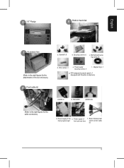
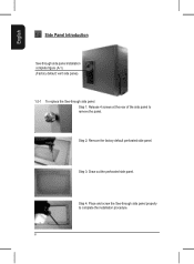
English English English English 1-2 Side Panel Introduction See-through side panel installation complete figure (A-1) (Factory default: vent side panel) 1-2-1 To replace the See-through side panel properly to remove the panel. Step 4: Place and screw the See-through side panel: Step 1: Release 4 screws at the rear of the side panel to complete the installation procedure. 6 Deutsch Deutsch English Step 2: Remove the factory default perforated side panel. Step 3: Draw out the perforated side panel.
English English English English 1-2 Side Panel Introduction See-through side panel installation complete figure (A-1) (Factory default: vent side panel) 1-2-1 To replace the See-through side panel properly to remove the panel. Step 4: Place and screw the See-through side panel: Step 1: Release 4 screws at the rear of the side panel to complete the installation procedure. 6 Deutsch Deutsch English Step 2: Remove the factory default perforated side panel. Step 3: Draw out the perforated side panel.
User Manual
Page 7
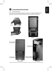
Figure a Figure b Front panel (B-1) Figure c Rear fan (C-1) English Deutsch Deutsch English Front fan (B-2) Drainage outlet(C-2) Front panel (B) Rear panel (C) 7 English English English 1-3 Front and Rear Panel Instruction 1-3-1 To remove front panel: Step 1: Remove the left and right side panels ( see Step 1-2-1 on Page 6) and slightly pull out both sides of the upper (see, Figure a) and lower (see Figure b) fasteners (see Figure c).
Figure a Figure b Front panel (B-1) Figure c Rear fan (C-1) English Deutsch Deutsch English Front fan (B-2) Drainage outlet(C-2) Front panel (B) Rear panel (C) 7 English English English 1-3 Front and Rear Panel Instruction 1-3-1 To remove front panel: Step 1: Remove the left and right side panels ( see Step 1-2-1 on Page 6) and slightly pull out both sides of the upper (see, Figure a) and lower (see Figure b) fasteners (see Figure c).
User Manual
Page 8
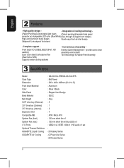
...fication Model Case Type Dimension Front bezel Material Color Side Panel Body Material Net Weight 5.25" drive bay (External) 3.5" drive bay (External) 3.5" drive bay (Internal) Expansion Slot Compatible MB System Fan (front) System Fan (rear) I /O (USBx2,IEEE1394x1, HD audiox1) Dual 12cm silent & shockproof fan (Rear fan w/ LED) Supports water cooling systems - Front bezel I / O Ports Optional Thermal Solutions GIGABYTE Liquid Cooling GIGABYTE Air Cooling : GZ-XA1CA-STB/GZ-XA1CA-STS : Mid-Tower : 200 x 440...
...fication Model Case Type Dimension Front bezel Material Color Side Panel Body Material Net Weight 5.25" drive bay (External) 3.5" drive bay (External) 3.5" drive bay (Internal) Expansion Slot Compatible MB System Fan (front) System Fan (rear) I /O (USBx2,IEEE1394x1, HD audiox1) Dual 12cm silent & shockproof fan (Rear fan w/ LED) Supports water cooling systems - Front bezel I / O Ports Optional Thermal Solutions GIGABYTE Liquid Cooling GIGABYTE Air Cooling : GZ-XA1CA-STB/GZ-XA1CA-STS : Mid-Tower : 200 x 440...
User Manual
Page 9
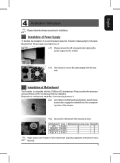
... 4 Installation Instruction Please follow the reference sections for installation. 4-1 Installation of the motherboard (typically supplied by motherboard manufactures). 9 English Motherboard ATX MINI ATX MICRO ATX FLEX ATX Code A1-A9 M1-M9 U1-U9 F1-F6 Motherboard securing screw 9 9 9 6 Standoffs 9 9 9 6 Select proper rear I/O panel of Power Supply To facilitate the installation, it is compatible with securing screws. English Deutsch Deutsch 4-2 Installation of the chassis. 4-2-2 Secure the motherboard...
... 4 Installation Instruction Please follow the reference sections for installation. 4-1 Installation of the motherboard (typically supplied by motherboard manufactures). 9 English Motherboard ATX MINI ATX MICRO ATX FLEX ATX Code A1-A9 M1-M9 U1-U9 F1-F6 Motherboard securing screw 9 9 9 6 Standoffs 9 9 9 6 Select proper rear I/O panel of Power Supply To facilitate the installation, it is compatible with securing screws. English Deutsch Deutsch 4-2 Installation of the chassis. 4-2-2 Secure the motherboard...
User Manual
Page 10
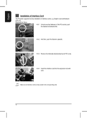
Make sure all interface cards are fully seated in the corresponding slots. 10 Deutsch Deutsch English English English English English 4-3 Installation of Interface Card The Poseidon supports tool-free installation of the PCI socket; Required tool: None 4-3-1 Unlock securing fasteners of interface cards, e.g. Graphic card and Network Card, etc. push the fastener downwards first. 4-3-2 And then, push the fastener upwards. 4-3-3 Remove the internally attached dust-proof PCI cover. 4-3-4 Insert the interface card into the expansion slot with care.
Make sure all interface cards are fully seated in the corresponding slots. 10 Deutsch Deutsch English English English English English 4-3 Installation of Interface Card The Poseidon supports tool-free installation of the PCI socket; Required tool: None 4-3-1 Unlock securing fasteners of interface cards, e.g. Graphic card and Network Card, etc. push the fastener downwards first. 4-3-2 And then, push the fastener upwards. 4-3-3 Remove the internally attached dust-proof PCI cover. 4-3-4 Insert the interface card into the expansion slot with care.
User Manual
Page 11
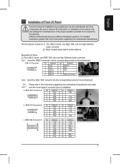
... High Definition Audio connector. (2) Basic chassis power switch control cable kit Required tool: None (1) Two USB 2.0 ports, one IEEE 1394, and one High Definition Audio connector. 4-4-1 Insert the USB2.0 connector into the corresponding socket on installation in the manual. Be sure to the instructions supplied by the motherboard manufacturer and make sure the correct type...
... High Definition Audio connector. (2) Basic chassis power switch control cable kit Required tool: None (1) Two USB 2.0 ports, one IEEE 1394, and one High Definition Audio connector. 4-4-1 Insert the USB2.0 connector into the corresponding socket on installation in the manual. Be sure to the instructions supplied by the motherboard manufacturer and make sure the correct type...
User Manual
Page 12
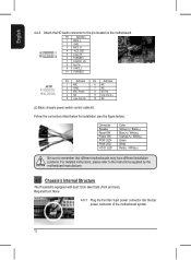
... 4-4-3 Attach the HD Audio connector to the instructions supplied by the motherboard manufacturer. 4-5 Chassis's Internal Structure The Poseidonis equipped with dual 12cm silent fans (front and rear). For detailed instructions, please refer to the pin located on the motherboard. Follow the connectors listed below for installation (see the figure below). LED Color Yellow(+) / Black(-) Blue(+) / White(-) Orange(+) / White...
... 4-4-3 Attach the HD Audio connector to the instructions supplied by the motherboard manufacturer. 4-5 Chassis's Internal Structure The Poseidonis equipped with dual 12cm silent fans (front and rear). For detailed instructions, please refer to the pin located on the motherboard. Follow the connectors listed below for installation (see the figure below). LED Color Yellow(+) / Black(-) Blue(+) / White(-) Orange(+) / White...
User Manual
Page 13
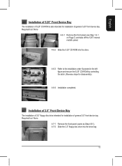
... Deutsch Deutsch English English English English English 4-6 Installation of 5.25" Front Device Bay The installation of 5.25" CD-ROM is also intended for installation of general 3.5" front device bay Required tool: None 4-7-1 Remove the front panel (same as Step 4-6-1). 4-7-2 Slide the 3.5" floppy disc drive into the drive. 4-6-3 Refer to the installation order illustrated in the left figure and...
... Deutsch Deutsch English English English English English 4-6 Installation of 5.25" Front Device Bay The installation of 5.25" CD-ROM is also intended for installation of general 3.5" front device bay Required tool: None 4-7-1 Remove the front panel (same as Step 4-6-1). 4-7-2 Slide the 3.5" floppy disc drive into the drive. 4-6-3 Refer to the installation order illustrated in the left figure and...
User Manual
Page 14
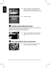
... front projector light 4-pin power cable into the 4-pin connector on both sides of the HDD evenly and slide the HDD into the hard disk drive bay. 4-9 Power cable installation of Built-in HDD (Hard Disc Drive) The Poseidon built-in the accessory box below. Required tools: 6 securing runners (in the accessory box) 4-8-1 Use the runners installed on the motherboard. 14...
... front projector light 4-pin power cable into the 4-pin connector on both sides of the HDD evenly and slide the HDD into the hard disk drive bay. 4-9 Power cable installation of Built-in HDD (Hard Disc Drive) The Poseidon built-in the accessory box below. Required tools: 6 securing runners (in the accessory box) 4-8-1 Use the runners installed on the motherboard. 14...

User Manual
Page 15
...4-10-3 Post the trimmed slide onto the transparent projector panel. 4-10-4 Remove the factory default plate located in the bottom of Projector Light The Poseidon is provided with another transparent projector panel, which can be provided by file name "...panel. (See Figure a and Figure b) 4-10-5 Push forward to search the Poseidon series case products by the user) 4-10-1 Please visit Gigabyte website (http:// gwebmanager1:7001/Products/Chassis/Default. Required tool: transparent projector panel (slides and laser printer or copy machine should be DIY designed and replaced...
...4-10-3 Post the trimmed slide onto the transparent projector panel. 4-10-4 Remove the factory default plate located in the bottom of Projector Light The Poseidon is provided with another transparent projector panel, which can be provided by file name "...panel. (See Figure a and Figure b) 4-10-5 Push forward to search the Poseidon series case products by the user) 4-10-1 Please visit Gigabyte website (http:// gwebmanager1:7001/Products/Chassis/Default. Required tool: transparent projector panel (slides and laser printer or copy machine should be DIY designed and replaced...
User Manual
Page 16
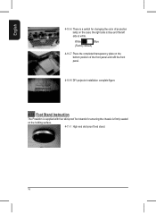
...case; White Blue (Factory default) 4-10-7 Place the completed transparency plate on the bottom position of projection lamp on the holding surface. 4-11-1 High-end skid-proof food stand. English Deutsch Deutsch English 16 English English English 4-10-6 There is a switch for changing the color of the front panel... and refit the front panel. 4-10-8 DIY projector installation complete figure. 4-11 Foot Stand Instruction The Poseidon is supplied with four skid-proof foot stands for ensuring the chassis is white....
...case; White Blue (Factory default) 4-10-7 Place the completed transparency plate on the bottom position of projection lamp on the holding surface. 4-11-1 High-end skid-proof food stand. English Deutsch Deutsch English 16 English English English 4-10-6 There is a switch for changing the color of the front panel... and refit the front panel. 4-10-8 DIY projector installation complete figure. 4-11 Foot Stand Instruction The Poseidon is supplied with four skid-proof foot stands for ensuring the chassis is white....
User Manual
Page 17
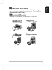
While installing the liquid cooling system, please consult its manual first. 4-13 Recommended Air Cooling The Poseidon is recommended to be used with the Gigabyte Air Cooling series. 17 Deutsch Deutsch English English English English English 4-12 Liquid Cooling System Support The Poseidon series chassis can fully support the Gigabyte 3D Galaxy Liquid cooling kit (also support most of the liquid cooling systems commercially available).
While installing the liquid cooling system, please consult its manual first. 4-13 Recommended Air Cooling The Poseidon is recommended to be used with the Gigabyte Air Cooling series. 17 Deutsch Deutsch English English English English English 4-12 Liquid Cooling System Support The Poseidon series chassis can fully support the Gigabyte 3D Galaxy Liquid cooling kit (also support most of the liquid cooling systems commercially available).