
Manual
Page 2
... 4 Software Install ...5 Prerequisites on remote management PC 5 Install Java Tool ...5 Gigabyte Content Management Network Configuration 6 Using the Web UI...8 Gigabyte Content Management System Console Overview 9 Enter Gigabyte Content Management System Console 10 Properties ...10 Configuration ...11 Network...11 Network Security ...12 Users ...13 Services ...14 IPMI ...15 Time Setting ...17 Sessions ...18 LDAP ...19 Updates ...20 Utilities ...21 Server Information ...22 Power Control ...22 Voltages ...23 Thermal ...24 Fans ...24 Temperature ...25 System Event Log ...26 Event Management...
... 4 Software Install ...5 Prerequisites on remote management PC 5 Install Java Tool ...5 Gigabyte Content Management Network Configuration 6 Using the Web UI...8 Gigabyte Content Management System Console Overview 9 Enter Gigabyte Content Management System Console 10 Properties ...10 Configuration ...11 Network...11 Network Security ...12 Users ...13 Services ...14 IPMI ...15 Time Setting ...17 Sessions ...18 LDAP ...19 Updates ...20 Utilities ...21 Server Information ...22 Power Control ...22 Voltages ...23 Thermal ...24 Fans ...24 Temperature ...25 System Event Log ...26 Event Management...

Manual
Page 12
... port. (Shared NIC Mode) Failover Mode When set to take effect of changes. 11 Configuration Network You can configure the BMC related settings through the BMC port. Shared Mode When set to Dedicate Mode, you can view and modify the network settings on this screen. Dedicate Mode When set to Shared Mode, you can configure the BMC related settings through the BMC or NIC2 port. (Backup Mode) When you finish configuration, click Apply Change. Select the Network Mode from the drop-down list...
... port. (Shared NIC Mode) Failover Mode When set to take effect of changes. 11 Configuration Network You can configure the BMC related settings through the BMC port. Shared Mode When set to Dedicate Mode, you can view and modify the network settings on this screen. Dedicate Mode When set to Shared Mode, you can configure the BMC related settings through the BMC or NIC2 port. (Backup Mode) When you finish configuration, click Apply Change. Select the Network Mode from the drop-down list...

Manual
Page 16
... Connection Mode Settings allows user to select the Console redirection type and to disable individual channels, or change the behavior of the out-of-band interfaces. Once the connection mode is communicating over. 15 Users This may be executed. An Administrator can be configured to be considered the lowest privilege level. The following table shows the Channel Privilege Level. Operator All BMC commands are allowed, including configuration commands...
... Connection Mode Settings allows user to select the Console redirection type and to disable individual channels, or change the behavior of the out-of-band interfaces. Once the connection mode is communicating over. 15 Users This may be executed. An Administrator can be configured to be considered the lowest privilege level. The following table shows the Channel Privilege Level. Operator All BMC commands are allowed, including configuration commands...

Manual
Page 10
... : Update Progress (If byte 2 is 06, this data is available.) e.g. ipmitool -H 10.1.27.150 -U admin -P password raw 0x2e 0x20 0x0a 0x3c 0x00 0x0e 0x00 0x00 0x0a 0x01 0x1b 0x34 0x69 0x6d 0x61 0x67 0x65 0x2e 0x52 0x42 0x55 Command format: raw : 0x69 0x6d 0x61 0x67 0x65 0x2e 0x52 0x42 0x55 = image.RBU [5] Check upload status e.g. GIGA...
... : Update Progress (If byte 2 is 06, this data is available.) e.g. ipmitool -H 10.1.27.150 -U admin -P password raw 0x2e 0x20 0x0a 0x3c 0x00 0x0e 0x00 0x00 0x0a 0x01 0x1b 0x34 0x69 0x6d 0x61 0x67 0x65 0x2e 0x52 0x42 0x55 Command format: raw : 0x69 0x6d 0x61 0x67 0x65 0x2e 0x52 0x42 0x55 = image.RBU [5] Check upload status e.g. GIGA...

Manual
Page 3
... Console (Linux 13 1-5-1 Tomcat Installation Procedure 13 1-5-2 PostgreSQL Installation Procedure 13 1-5-3 Restore dbRMCv0XX.backup 14 1-5-4 pgadminIII Installation Procedure (Optional 15 1-5-5 Login Gigabyte Server Management Console 16 Chapter 2 Gigabyte Server Management Console 17 2-1 Overview...17 2-2 Enter Gigabyte Server Management Console 18 2-2-1 Node Info...18 2-2-1-1 Node ID...20 Power Consumption...20 SEL ...21 Node Detail...21 Chassis ...22 Sensor ...23 Trap IP Destination List...24 Platform Events...25 BMC Update...26 BIOS Update...26 Power Limit...27 IPv6 Configuration...
... Console (Linux 13 1-5-1 Tomcat Installation Procedure 13 1-5-2 PostgreSQL Installation Procedure 13 1-5-3 Restore dbRMCv0XX.backup 14 1-5-4 pgadminIII Installation Procedure (Optional 15 1-5-5 Login Gigabyte Server Management Console 16 Chapter 2 Gigabyte Server Management Console 17 2-1 Overview...17 2-2 Enter Gigabyte Server Management Console 18 2-2-1 Node Info...18 2-2-1-1 Node ID...20 Power Consumption...20 SEL ...21 Node Detail...21 Chassis ...22 Sensor ...23 Trap IP Destination List...24 Platform Events...25 BMC Update...26 BIOS Update...26 Power Limit...27 IPv6 Configuration...

Manual
Page 38
... power limit fail Get SEL fail Get SDR fail Set trap IP/enable destination fail Set platform events fail Set IPv6 trap IP/enable destination fail Get platform events fail Get IPv6 trap IP/enable destination fail Match rack node info fail Match RMC/BMC IP fail Get FRU fail Save Event Log to log file fail Copy catalina file fail Close file channel fail Get power status fail Send chassis command fail Set IPv6 enable/disable configuration fail Get power reading fail Get CPU temperature fail Set boot option fail Set chassis identify fail Power limit deactivate Description Network is not connected...
... power limit fail Get SEL fail Get SDR fail Set trap IP/enable destination fail Set platform events fail Set IPv6 trap IP/enable destination fail Get platform events fail Get IPv6 trap IP/enable destination fail Match rack node info fail Match RMC/BMC IP fail Get FRU fail Save Event Log to log file fail Copy catalina file fail Close file channel fail Get power status fail Send chassis command fail Set IPv6 enable/disable configuration fail Get power reading fail Get CPU temperature fail Set boot option fail Set chassis identify fail Power limit deactivate Description Network is not connected...
Manual
Page 4
... System Block Diagram 14 1-3-1 H270-F4G...14 1-3-2 H270-H70...15 Chapter 2 System Hardware Installation 16 2-1 System Components 17 2-2 Replacing Power Supply Board Cage Cover 18 2-3 Replacing the Motherboard Tray 19 2-4 Removing and Installing the Fan Duct 20 2-5 Installing the CPU 21 2-6 Installing the Heat Sink 22 2-7 Installing the Memory 24 2-7-1 Four Channel Memory Configuration 24 2-7-2 Installing a Memory 25 2-8 Installing the PCI Express Expansion Card 26 2-8-1 Installing Add-on Card (Optional 27 2-9 Installing the Hard Disk Drive 28 2-10 Replacing the Power Supply 29...
... System Block Diagram 14 1-3-1 H270-F4G...14 1-3-2 H270-H70...15 Chapter 2 System Hardware Installation 16 2-1 System Components 17 2-2 Replacing Power Supply Board Cage Cover 18 2-3 Replacing the Motherboard Tray 19 2-4 Removing and Installing the Fan Duct 20 2-5 Installing the CPU 21 2-6 Installing the Heat Sink 22 2-7 Installing the Memory 24 2-7-1 Four Channel Memory Configuration 24 2-7-2 Installing a Memory 25 2-8 Installing the PCI Express Expansion Card 26 2-8-1 Installing Add-on Card (Optional 27 2-9 Installing the Hard Disk Drive 28 2-10 Replacing the Power Supply 29...
Manual
Page 8
... the risk of any kind into the network interface controller (NIC) receptacle. • Disconnect the modem cable before opening a product enclosure, touching or installing internalcompo- This is in accordance with its marked electricalratings and product usage instructions • Do not use this product near water or a heat source.* Set up your computer has a voltage selector switch, make adjustments, or perform procedures on the...
... the risk of any kind into the network interface controller (NIC) receptacle. • Disconnect the modem cable before opening a product enclosure, touching or installing internalcompo- This is in accordance with its marked electricalratings and product usage instructions • Do not use this product near water or a heat source.* Set up your computer has a voltage selector switch, make adjustments, or perform procedures on the...
Manual
Page 12
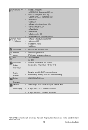
... 4 USB 3.0 ports ( 2 on the rear panel I/O, 2 additional ports via the USB brackets connected to the internal USB headers) ŠŠ 2 x 18-pin power connectors ŠŠ 1 x Front panel header ŠŠ 6 x SATA3 6Gb/s connectors ŠŠ 1 x USB 3.0 header ŠŠ 1 x TPM module connector ŠŠ 1 x SATA SPGIO header ŠŠ 1 x BMC SPGIO header ŠŠ 1 x PMBUS header ŠŠ 1 x IPMB connector ŠŠ 1 x Software RAID key connector ŠŠ 1 x SATA Power connector (H270-H70 Only) ŠŠ 1 x Mananement LAN port cable...
... 4 USB 3.0 ports ( 2 on the rear panel I/O, 2 additional ports via the USB brackets connected to the internal USB headers) ŠŠ 2 x 18-pin power connectors ŠŠ 1 x Front panel header ŠŠ 6 x SATA3 6Gb/s connectors ŠŠ 1 x USB 3.0 header ŠŠ 1 x TPM module connector ŠŠ 1 x SATA SPGIO header ŠŠ 1 x BMC SPGIO header ŠŠ 1 x PMBUS header ŠŠ 1 x IPMB connector ŠŠ 1 x Software RAID key connector ŠŠ 1 x SATA Power connector (H270-H70 Only) ŠŠ 1 x Mananement LAN port cable...
Manual
Page 13
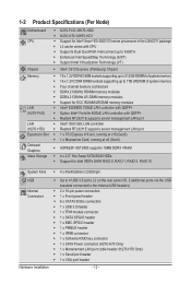
Hardware Installation Rear Panel I/O Front Panel LED/Buttons I/O Controller Hardware Monitor BIOS Environment Ambient Temperature ŠŠ 2 x USB 2.0/3.0 ports ŠŠ 1 x 10/100/1000 Management LAN port ŠŠ 2 x RJ-45 ports (H270-H70 Only) ŠŠ 1 x QSFP+ LAN port (H270-F4G Only) ŠŠ 1 x Serial port ŠŠ 1 x VGA port ŠŠ 1 x Power switch button/status LED ŠŠ 1 x ID switch button/LED ŠŠ 1 x Reset button ŠŠ 1 x NMI button ŠŠ 1 x System status LED ŠŠ 2 x LAN Link/Active LED (LAN1/LAN2) Š...
Hardware Installation Rear Panel I/O Front Panel LED/Buttons I/O Controller Hardware Monitor BIOS Environment Ambient Temperature ŠŠ 2 x USB 2.0/3.0 ports ŠŠ 1 x 10/100/1000 Management LAN port ŠŠ 2 x RJ-45 ports (H270-H70 Only) ŠŠ 1 x QSFP+ LAN port (H270-F4G Only) ŠŠ 1 x Serial port ŠŠ 1 x VGA port ŠŠ 1 x Power switch button/status LED ŠŠ 1 x ID switch button/LED ŠŠ 1 x Reset button ŠŠ 1 x NMI button ŠŠ 1 x System status LED ŠŠ 2 x LAN Link/Active LED (LAN1/LAN2) Š...
Manual
Page 39
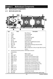
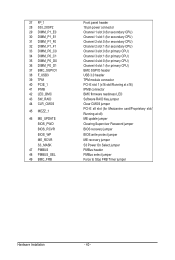
... Code Description Rear VGA port Front VGA header Rear serial port 4 COM2 Front serial port header 5 SW_PWR1 Power button/LED 6 SW_ID ID switch button 7 SW_RST_NMI Reset button (top)/NMI button (buttom) 8 LED_STA System status LED 9 LED_LAN LAN1 (buttom)/LAN2 (top) Active/Link LEDs 10 QSFP_1 QSFP LAN port 11 USB3_LAN1 BMC management LAN port (top)/USB 3.0 ports (buttom) 12 SATA0/SATA1/SATA 2/SATA3/ SATA 6Gb/s connectors SATA4/SATA5 13 BAT1 14 SATA_SGP1 15 DIMM_P0_A0 16 DIMM_P0_A1 Battery socket SATA SGPIO header Channel 1 slot 0 (for primary CPU...
... Code Description Rear VGA port Front VGA header Rear serial port 4 COM2 Front serial port header 5 SW_PWR1 Power button/LED 6 SW_ID ID switch button 7 SW_RST_NMI Reset button (top)/NMI button (buttom) 8 LED_STA System status LED 9 LED_LAN LAN1 (buttom)/LAN2 (top) Active/Link LEDs 10 QSFP_1 QSFP LAN port 11 USB3_LAN1 BMC management LAN port (top)/USB 3.0 ports (buttom) 12 SATA0/SATA1/SATA 2/SATA3/ SATA 6Gb/s connectors SATA4/SATA5 13 BAT1 14 SATA_SGP1 15 DIMM_P0_A0 16 DIMM_P0_A1 Battery socket SATA SGPIO header Channel 1 slot 0 (for primary CPU...
Manual
Page 40
... primary CPU) Channel 3 slot 1 (for primary CPU) Channel 4 slot 0 (for primary CPU) Channel 4 slot 1 (for primary CPU) BMC SGPIO header USB 3.0 header TPM module connector PCI-E slot 1 (x16 slot/Running at x16) IPMB connector BMC firmware readiness LED Software RAID Key jumper Clear CMOS jumper PCI-E x8 slot (for Mezzanine card/Proprietary slot/ Running at x8) ME update jumper Clearing Supervisor Password jumper BIOS recovery jumper BIOS write protect jumper ME recovery jumper S3 Power On Select jumper PMBus header PMBus select jumper Force to Stop FRB Timer jumper Hardware Installation - 40...
... primary CPU) Channel 3 slot 1 (for primary CPU) Channel 4 slot 0 (for primary CPU) Channel 4 slot 1 (for primary CPU) BMC SGPIO header USB 3.0 header TPM module connector PCI-E slot 1 (x16 slot/Running at x16) IPMB connector BMC firmware readiness LED Software RAID Key jumper Clear CMOS jumper PCI-E x8 slot (for Mezzanine card/Proprietary slot/ Running at x8) ME update jumper Clearing Supervisor Password jumper BIOS recovery jumper BIOS write protect jumper ME recovery jumper S3 Power On Select jumper PMBus header PMBus select jumper Force to Stop FRB Timer jumper Hardware Installation - 40...
Manual
Page 41
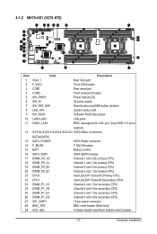
... 3 COM1 Rear VGA port Front VGA header Rear serial port 4 COM2 Front serial port header 5 SW_PWR1 Power button/LED 6 SW_ID ID switch button 7 SW_RST_NMI Reset button (top)/NMI button (buttom) 8 LED_STA System status LED 9 SW_RAID Software RAID Key jumper 10 LAN1/LAN2 LAN ports 11 USB3_LAN1 BMC management LAN port (top)/USB 3.0 ports (buttom) 12 SATA0/SATA1/SATA 2/SATA3/ SATA 6Gb/s connectors SATA4/SATA5 13 SATA_POWER 14 F_MLAN 15 BAT1 16 SATA_SGP1 SATA Power connector F_MLAN header Battery socket SATA SGPIO header 17 DIMM_P0_A0 Channel 1 slot 0 (for primary CPU) 18...
... 3 COM1 Rear VGA port Front VGA header Rear serial port 4 COM2 Front serial port header 5 SW_PWR1 Power button/LED 6 SW_ID ID switch button 7 SW_RST_NMI Reset button (top)/NMI button (buttom) 8 LED_STA System status LED 9 SW_RAID Software RAID Key jumper 10 LAN1/LAN2 LAN ports 11 USB3_LAN1 BMC management LAN port (top)/USB 3.0 ports (buttom) 12 SATA0/SATA1/SATA 2/SATA3/ SATA 6Gb/s connectors SATA4/SATA5 13 SATA_POWER 14 F_MLAN 15 BAT1 16 SATA_SGP1 SATA Power connector F_MLAN header Battery socket SATA SGPIO header 17 DIMM_P0_A0 Channel 1 slot 0 (for primary CPU) 18...
Manual
Page 46
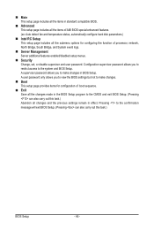
... items of AMI BIOS special enhanced features. (ex: Auto detect fan and temperature status, automatically configure hard disk parameters.) Intel RC Setup This setup page includes all the submenu options for configuration of processor, network, North Bridge, South Bridge, and System event logs. Server Management Server additional features enabled/disabled setup menus. Security Change, set, or disable supervisor and user password. A supervisor password allows you to restrict access to the CMOS and exit BIOS Setup. (Pressing can also...
... items of AMI BIOS special enhanced features. (ex: Auto detect fan and temperature status, automatically configure hard disk parameters.) Intel RC Setup This setup page includes all the submenu options for configuration of processor, network, North Bridge, South Bridge, and System event logs. Server Management Server additional features enabled/disabled setup menus. Security Change, set, or disable supervisor and user password. A supervisor password allows you to restrict access to the CMOS and exit BIOS Setup. (Pressing can also...
Manual
Page 72
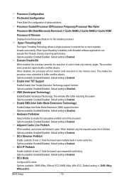
...: Enabled/Disabled. Options available: Enabled/Disabled. Enable Intel TXT Support Enable/Disable Intel Trusted Execution Technology support function. BIOS Setup - 72 - Default setting is Disabled. This will not restrict code execution in same cache line. Adjacent Cache Line Prefetch When enabled, cache lines are fetched in data-only memory pages. Default setting is enabled, multi-threaded software applications can execute their threads, thereby improving performance. When hyper-threading is Enabled. Execute Disable Bit When enabled, the processor...
...: Enabled/Disabled. Options available: Enabled/Disabled. Enable Intel TXT Support Enable/Disable Intel Trusted Execution Technology support function. BIOS Setup - 72 - Default setting is Disabled. This will not restrict code execution in same cache line. Adjacent Cache Line Prefetch When enabled, cache lines are fetched in data-only memory pages. Default setting is enabled, multi-threaded software applications can execute their threads, thereby improving performance. When hyper-threading is Enabled. Execute Disable Bit When enabled, the processor...
Manual
Page 83
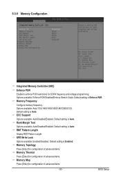
.... ECC Support Options available: Auto/Disabled/Enabled. Default setting is Auto. Rank Margin Tool Options available: Auto/Disabled/Enabled. BIOS Setup Default setting is Auto. RMT Pattern Length Display RMT Pattern Length. SPD Write Lock Options available: Enabled/Disabled. Default setting is Enforce POR. Default setting is Auto. 5-3-5 Memory Configuration Integrated Memory Controller (iMC) Enforce POR Enable to enforce POR restrictions for configuration of advanced items. Memory Map Press [Enter] for DDR4 frequency and voltage programming...
.... ECC Support Options available: Auto/Disabled/Enabled. Default setting is Auto. Rank Margin Tool Options available: Auto/Disabled/Enabled. BIOS Setup Default setting is Auto. RMT Pattern Length Display RMT Pattern Length. SPD Write Lock Options available: Enabled/Disabled. Default setting is Enforce POR. Default setting is Auto. 5-3-5 Memory Configuration Integrated Memory Controller (iMC) Enforce POR Enable to enforce POR restrictions for configuration of advanced items. Memory Map Press [Enter] for DDR4 frequency and voltage programming...
Manual
Page 87
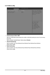
5-3-5-3 Memory Map Socket Interleave Below 4GB Splits the 0-4GB address space between two sockets, so that both sockets get a chunk of local memory below 4GB. Default setting is Disabled. Default setting is Auto. BIOS Setup Channel Interleaving Options available: Auto/1-way Interleave/2-way Interleave/3-way Interleave/4-way Interleave. Default setting is Auto. - 87 - Rank Interleaving Options available: Auto/1-way Interleave/2-way Interleave/4-way Interleave/8-way Interleave. Options available: Disabled/Enabled.
5-3-5-3 Memory Map Socket Interleave Below 4GB Splits the 0-4GB address space between two sockets, so that both sockets get a chunk of local memory below 4GB. Default setting is Disabled. Default setting is Auto. BIOS Setup Channel Interleaving Options available: Auto/1-way Interleave/2-way Interleave/3-way Interleave/4-way Interleave. Default setting is Auto. - 87 - Rank Interleaving Options available: Auto/1-way Interleave/2-way Interleave/4-way Interleave/8-way Interleave. Options available: Disabled/Enabled.
Manual
Page 88
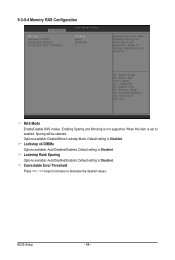
Default setting is Disabled. Default setting is Disabled. When this item is Disabled. Options available: Disable/Mirror/Lockstep Mode. Lockstep Rank Sparing Options available: Auto/Disabled/Enabled. Correctable Error Threshold Press / keys to enabled, Sparing will be selected. Default setting is set to increase or decrease the desired values. Lockstep x4 DIMMs Options available: Auto/Disabled/Enabled. 5-3-5-4 Memory RAS Configuration RAS Mode Enable/Disable RAS modes. BIOS Setup - 88 - Enabling Sparing and Mirroring is not supported.
Default setting is Disabled. Default setting is Disabled. When this item is Disabled. Options available: Disable/Mirror/Lockstep Mode. Lockstep Rank Sparing Options available: Auto/Disabled/Enabled. Correctable Error Threshold Press / keys to enabled, Sparing will be selected. Default setting is set to increase or decrease the desired values. Lockstep x4 DIMMs Options available: Auto/Disabled/Enabled. 5-3-5-4 Memory RAS Configuration RAS Mode Enable/Disable RAS modes. BIOS Setup - 88 - Enabling Sparing and Mirroring is not supported.
Manual
Page 102
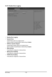
S/W Error Injection Support Enable/Disable software injection error logging function. Options available: Enabled/Disabled. Default setting is Enabled. Options available: Enabled/Disabled. Whea Settings Press [Enter] for configuration of advanced items. Memory Error Enabling Press [Enter] for configuration of advanced items. PCI/PCI Error Enabling Press [Enter] for configuration of advanced items. BIOS Setup - 102 - Default setting is Enabled. 5-3-10 Runtime Error Logging Runtime Error Logging System Errors Enable/Disable system error logging function.
S/W Error Injection Support Enable/Disable software injection error logging function. Options available: Enabled/Disabled. Default setting is Enabled. Options available: Enabled/Disabled. Whea Settings Press [Enter] for configuration of advanced items. Memory Error Enabling Press [Enter] for configuration of advanced items. PCI/PCI Error Enabling Press [Enter] for configuration of advanced items. BIOS Setup - 102 - Default setting is Enabled. 5-3-10 Runtime Error Logging Runtime Error Logging System Errors Enable/Disable system error logging function.
Manual
Page 103
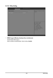
BIOS Setup 5-3-10-1 Whea Setting WHEA Support (Windows Hardware Error Architecture) Enable/Disable WHEA Support. Options available: Enabled/Disabled. Default setting is Enabled. - 103 -
BIOS Setup 5-3-10-1 Whea Setting WHEA Support (Windows Hardware Error Architecture) Enable/Disable WHEA Support. Options available: Enabled/Disabled. Default setting is Enabled. - 103 -