
Manual
Page 3
... Box Contents...4 M5NM1I Motherboard Layout 5 Chapter 1 Hardware Installation 7 1-1 Installation Precautions 7 1-2 Product Specifications 8 1-3 Installing the Memory 10 1-3-1 Dual Channel Memory Configuration 10 1-3-2 Installing a Memory 11 1-4 Back Panel Connectors 12 1-5 Internal Connectors 13 Chapter 2 BIOS Setup 26 2-1 The Main Menu 28 2-2 Advanced Menu 30 2-2-1 CPU Configuration 31 2-2-2 SATA Configuration 33 2-2-3 USB Configuration 35 2-2-4 F81214 Super IO Configuration 37 2-2-5 H/W Monitor...39 2-3 Chipset Menu 40 2-4 Boot Menu...41 2-5 Security Menu 43 2-6 Save...
... Box Contents...4 M5NM1I Motherboard Layout 5 Chapter 1 Hardware Installation 7 1-1 Installation Precautions 7 1-2 Product Specifications 8 1-3 Installing the Memory 10 1-3-1 Dual Channel Memory Configuration 10 1-3-2 Installing a Memory 11 1-4 Back Panel Connectors 12 1-5 Internal Connectors 13 Chapter 2 BIOS Setup 26 2-1 The Main Menu 28 2-2 Advanced Menu 30 2-2-1 CPU Configuration 31 2-2-2 SATA Configuration 33 2-2-3 USB Configuration 35 2-2-4 F81214 Super IO Configuration 37 2-2-5 H/W Monitor...39 2-3 Chipset Menu 40 2-4 Boot Menu...41 2-5 Security Menu 43 2-6 Save...
Manual
Page 6
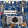
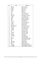
... 2.0 ports HDMI port RJ45 LAN port DC In power connector 2 pin power connector Mini PCi Express connector Front USB connector Serial port cable header Serial port cable header TPM moudle header LAN LED header Back Light switch header Front panel header WF LED header SATA cable connectors Hard disk power connector Front USB connector Audio cable connector CPU fan connector Embedded porcessor System fan connector VGA cable connector Battery socket Clear CMOS jumper Intel 82NM10 chipset LVDS Enable/Disable jumper Flat Panel Display connector LVDS connector Digital Mic header WEBCAM header Speaker...
... 2.0 ports HDMI port RJ45 LAN port DC In power connector 2 pin power connector Mini PCi Express connector Front USB connector Serial port cable header Serial port cable header TPM moudle header LAN LED header Back Light switch header Front panel header WF LED header SATA cable connectors Hard disk power connector Front USB connector Audio cable connector CPU fan connector Embedded porcessor System fan connector VGA cable connector Battery socket Clear CMOS jumper Intel 82NM10 chipset LVDS Enable/Disable jumper Flat Panel Display connector LVDS connector Digital Mic header WEBCAM header Speaker...

Manual
Page 7
... come in a high-temperature environment. • Turning on the computer power during the installation process can become damaged as a motherboard, CPU or memory. If you do not remove or break motherboard S/N (Serial Number) sticker or warranty sticker provided by unplugging the power cord from the motherboard, make sure the power supply has been turned off. • Before turning on the motherboard, make sure the power supply voltage has been set according to...
... come in a high-temperature environment. • Turning on the computer power during the installation process can become damaged as a motherboard, CPU or memory. If you do not remove or break motherboard S/N (Serial Number) sticker or warranty sticker provided by unplugging the power cord from the motherboard, make sure the power supply has been turned off. • Before turning on the motherboard, make sure the power supply voltage has been set according to...
Manual
Page 8
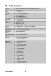
... PCI Express slot (Half size) Onboard ŠŠ Build in Intel® processor Graphics Storage Interface ŠŠ 2 x SATA 3Gb/s connectors USB Internal Connectors ŠŠ 4 x USB 2.0 ports (back panel) ŠŠ 2 x USB 2.0/1.1 headers ŠŠ 1 x 2-pin power connector ŠŠ 1 x TPM header ŠŠ 2 x SATA 3Gb/s connectors ŠŠ 1 x HDD power connector ŠŠ 1 x CPU fan header ŠŠ 1 x System fan header ŠŠ 1 x Front panel header ŠŠ 1 x Audio header ŠŠ 2 x USB 2.0 headers ŠŠ 1 x Speaker header...
... PCI Express slot (Half size) Onboard ŠŠ Build in Intel® processor Graphics Storage Interface ŠŠ 2 x SATA 3Gb/s connectors USB Internal Connectors ŠŠ 4 x USB 2.0 ports (back panel) ŠŠ 2 x USB 2.0/1.1 headers ŠŠ 1 x 2-pin power connector ŠŠ 1 x TPM header ŠŠ 2 x SATA 3Gb/s connectors ŠŠ 1 x HDD power connector ŠŠ 1 x CPU fan header ŠŠ 1 x System fan header ŠŠ 1 x Front panel header ŠŠ 1 x Audio header ŠŠ 2 x USB 2.0 headers ŠŠ 1 x Speaker header...
Manual
Page 10
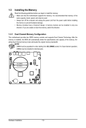
.... It is installed, the BIOS will double the original memory bandwidth. Enabling Dual Channel memory mode will automatically detect the specifications and capacity of the same capacity, brand, speed, and chips be populated in order starting from the power outlet before you are unable to insert the memory, switch the direction. 1-3-1 Dual Channel Memory Configuration This motherboard provides two DDR3 memory sockets and supports Dual Channel Technology. 1-3 Installing the Memory Read the following guidelines before installing the memory to prevent...
.... It is installed, the BIOS will double the original memory bandwidth. Enabling Dual Channel memory mode will automatically detect the specifications and capacity of the same capacity, brand, speed, and chips be populated in order starting from the power outlet before you are unable to insert the memory, switch the direction. 1-3-1 Dual Channel Memory Configuration This motherboard provides two DDR3 memory sockets and supports Dual Channel Technology. 1-3 Installing the Memory Read the following guidelines before installing the memory to prevent...
Manual
Page 11
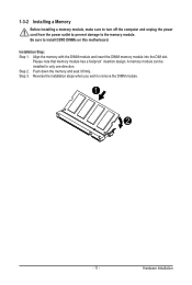
Installation Step: Step 1. A memory module can be installed In only one direction. Hardware Installation 1-3-2 Installing a Memory Before installing a memory module, make sure to turn off the computer and unplug the power cord from the power outlet to prevent damage to remove the DIMM module. 1 2 - 11 - Step 2. Reverse the installation steps when you wish to the memory module. Be sure to install DDR3 DIMMs on this motherboard. Align...
Installation Step: Step 1. A memory module can be installed In only one direction. Hardware Installation 1-3-2 Installing a Memory Before installing a memory module, make sure to turn off the computer and unplug the power cord from the power outlet to prevent damage to remove the DIMM module. 1 2 - 11 - Step 2. Reverse the installation steps when you wish to the memory module. Be sure to install DDR3 DIMMs on this motherboard. Align...

Manual
Page 12
... the default device for line in devices such as a USB keyboard/mouse, USB printer, USB flash drive and etc. Use this port for decoding.) USB 2.0 Port The USB port supports the USB 2.0 specification. The following describes the states of an external decoder for USB devices such as an optical drive, walkman, etc. Refer the figures below for a headphone or 2-channel speaker. Use this audio jack for details.), and enter BIOS Setup, then set Onboard VGA output connect to 1 Gbps data rate. Connection/ Speed LED Activity LED LAN Port Connection/Speed LED...
... the default device for line in devices such as a USB keyboard/mouse, USB printer, USB flash drive and etc. Use this port for decoding.) USB 2.0 Port The USB port supports the USB 2.0 specification. The following describes the states of an external decoder for USB devices such as an optical drive, walkman, etc. Refer the figures below for a headphone or 2-channel speaker. Use this audio jack for details.), and enter BIOS Setup, then set Onboard VGA output connect to 1 Gbps data rate. Connection/ Speed LED Activity LED LAN Port Connection/Speed LED...
Manual
Page 17
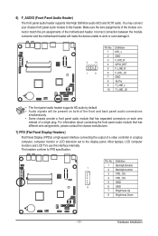
... monitor or LCD television set to this interface internally. Definition 1 MIC_L 2 GND 2 10 3 F_MIC_R 4 GPIO_DET 5 F_LINE_R 1 9 6 F_MIC_JD 7 GND 8 No Pin 9 F_LINE_L 10 F_LINE_JD • The front panel audio header supports HD audio by default. • Audio signals will make the device unable to FPD specification. Pin No. Incorrect connection between the module connector and the motherboard header will be present on each wire instead of the motherboard header. Pin No. Hardware Installation Make...
... monitor or LCD television set to this interface internally. Definition 1 MIC_L 2 GND 2 10 3 F_MIC_R 4 GPIO_DET 5 F_LINE_R 1 9 6 F_MIC_JD 7 GND 8 No Pin 9 F_LINE_L 10 F_LINE_JD • The front panel audio header supports HD audio by default. • Audio signals will make the device unable to FPD specification. Pin No. Incorrect connection between the module connector and the motherboard header will be present on each wire instead of the motherboard header. Pin No. Hardware Installation Make...

Manual
Page 19
... fan headers are not configuration jumper blocks. When connecting a fan cable, be installed inside the chassis. 1 1 Pin No. 1 2 3 4 Definition GND +12V Sense Speed Control CPU_FAN SYS_FAN • Be sure to connect fan cables to the fan headers to connect it is the ground wire). Do not place a jumper cap on the headers. - 19 - Hardware Installation Most fan headers possess a foolproof insertion design. The motherboard supports CPU fan speed control, which requires the use of a CPU fan with fan speed control design. 10) VGA_PH (VGA Cable Connector) 1 11 2 12 Pin...
... fan headers are not configuration jumper blocks. When connecting a fan cable, be installed inside the chassis. 1 1 Pin No. 1 2 3 4 Definition GND +12V Sense Speed Control CPU_FAN SYS_FAN • Be sure to connect fan cables to the fan headers to connect it is the ground wire). Do not place a jumper cap on the headers. - 19 - Hardware Installation Most fan headers possess a foolproof insertion design. The motherboard supports CPU fan speed control, which requires the use of a CPU fan with fan speed control design. 10) VGA_PH (VGA Cable Connector) 1 11 2 12 Pin...
Manual
Page 23
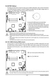
... to replace the battery by removing the battery: 1. Turn off . 19) BATTERY (Battery) The battery provides power to keep the values (such as BIOS configurations, date, and time information) in accordance with local environmental regulations. 20) CLR_CMOS (Clearing CMOS Jumper) Use this jumper to clear the CMOS values (e.g. Replace the battery. 4. date information and BIOS configurations) and reset the CMOS values to the motherboard. - 23 - You may be sure to touch the two pins for 5 seconds.) 3. Plug...
... to replace the battery by removing the battery: 1. Turn off . 19) BATTERY (Battery) The battery provides power to keep the values (such as BIOS configurations, date, and time information) in accordance with local environmental regulations. 20) CLR_CMOS (Clearing CMOS Jumper) Use this jumper to clear the CMOS values (e.g. Replace the battery. 4. date information and BIOS configurations) and reset the CMOS values to the motherboard. - 23 - You may be sure to touch the two pins for 5 seconds.) 3. Plug...

Manual
Page 26
... the battery/ clearing CMOS jumper in system malfunction. • It is recommended that you need to) to select the screen Execute command or enter the submenu Main Menu: Exit the BIOS Setup program Submenus: Exit current submenu Increase the numeric value or make changes Decrease the numeric value or make changes General Help Restore the previous BIOS settings for the current submenus Load the Optimized BIOS default settings...
... the battery/ clearing CMOS jumper in system malfunction. • It is recommended that you need to) to select the screen Execute command or enter the submenu Main Menu: Exit the BIOS Setup program Submenus: Exit current submenu Increase the numeric value or make changes Decrease the numeric value or make changes General Help Restore the previous BIOS settings for the current submenus Load the Optimized BIOS default settings...
Manual
Page 27
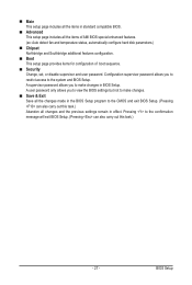
...: Auto detect fan and temperature status, automatically configure hard disk parameters.) Chipset Northbridge and Southbridge additional features configuration. Boot This setup page provides items for configuration of boot sequence. Security Change, set, or disable supervisor and user password. A user password only allows you to restrict access to the CMOS and exit BIOS Setup. (Pressing can also carry out this task.) Abandon all changes and the previous settings remain in effect. Main This setup...
...: Auto detect fan and temperature status, automatically configure hard disk parameters.) Chipset Northbridge and Southbridge additional features configuration. Boot This setup page provides items for configuration of boot sequence. Security Change, set, or disable supervisor and user password. A user password only allows you to restrict access to the CMOS and exit BIOS Setup. (Pressing can also carry out this task.) Abandon all changes and the previous settings remain in effect. Main This setup...
Manual
Page 30
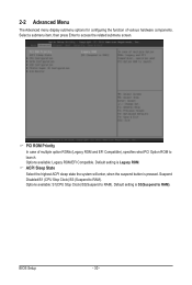
... Menu The Advanced menu display submenu options for configuring the function of multiple option ROMs (Legacy ROM and EFI Compatible), specifies what PCI Option ROM to launch. Options available: Legacy ROM/EFI Compatible. BIOS Setup - 30 - Default setting is pressed. Default setting is S3(Suspend to RAM). Suspend Disabled/S1 (CPU Stop Clock)/S3 (Suspend to RAM). Options available: S1(CPU Stop Clock)/S3(Suspend to access the related submenu screen. ACPI Sleep State Select the highest ACPI sleep state the system will enter, when the suspend button is Legacy ROM...
... Menu The Advanced menu display submenu options for configuring the function of multiple option ROMs (Legacy ROM and EFI Compatible), specifies what PCI Option ROM to launch. Options available: Legacy ROM/EFI Compatible. BIOS Setup - 30 - Default setting is pressed. Default setting is S3(Suspend to RAM). Suspend Disabled/S1 (CPU Stop Clock)/S3 (Suspend to RAM). Options available: S1(CPU Stop Clock)/S3(Suspend to access the related submenu screen. ACPI Sleep State Select the highest ACPI sleep state the system will enter, when the suspend button is Legacy ROM...

Manual
Page 33
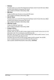
... device casing. Disabled: The data transfer from and to set all HDD parameters automatically. Default setting is installed here. LBA/Large Mode Configure the device type in the computer. 2-2-2 SATA Configuration SATA Configuration SATA Port 0/SATA Port 1 The category identifies Serial ATA and mSATA types of hard disk that the specifications of Multi-Sector Transfer Mode. ARMD: Use ARMD drive is Auto. Option available: Auto/Disabled. System will not work properly if you enter improper information for ATAPI CD-ROM drives or double click [Auto] to the device...
... device casing. Disabled: The data transfer from and to set all HDD parameters automatically. Default setting is installed here. LBA/Large Mode Configure the device type in the computer. 2-2-2 SATA Configuration SATA Configuration SATA Port 0/SATA Port 1 The category identifies Serial ATA and mSATA types of hard disk that the specifications of Multi-Sector Transfer Mode. ARMD: Use ARMD drive is Auto. Option available: Auto/Disabled. System will not work properly if you enter improper information for ATAPI CD-ROM drives or double click [Auto] to the device...
Manual
Page 34
...the specific IDE channel. BIOS Setup - 34 - Default setting is not allowed to access RAID setup utility. S.M.A.R.T Mode This feature allows you to set the PIO (Programmed Input/Output) mode for the two IDE devices (Master and Slave drives) attached to that particular IDE channel. You will be access the RAID setup utility at boot time. Option available: Auto/Disabled. AHCI Mode: When set to AHCI,the SATA controller enables its AHCI functionality. Option available: Auto/Disabled. This is Auto. Options available: IDE/RAID/AHCI/Disabled. Option available: Auto/Disabled...
...the specific IDE channel. BIOS Setup - 34 - Default setting is not allowed to access RAID setup utility. S.M.A.R.T Mode This feature allows you to set the PIO (Programmed Input/Output) mode for the two IDE devices (Master and Slave drives) attached to that particular IDE channel. You will be access the RAID setup utility at boot time. Option available: Auto/Disabled. AHCI Mode: When set to AHCI,the SATA controller enables its AHCI functionality. Option available: Auto/Disabled. This is Auto. Options available: IDE/RAID/AHCI/Disabled. Option available: Auto/Disabled...
Manual
Page 35
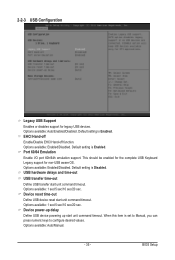
... USB transfer start unit command timeout. Options available: 1 sec/5 sec/10 sec/20 sec. Options available: 1 sec/5 sec/10 sec/20 sec. Default setting is Enabled. Device power-up delay Define USB device powering up start unit command timeout. When this item is Enabled. Options available: Enabled/Disabled. Default setting is set to Manual, you can press numeric keys to configure desired values. Options available: Auto/Manual. - 35 - This should be enabled for the complete USB Keyboard Legacy support for legacy USB devices. Options available: Auto/Enabled/Disabled...
... USB transfer start unit command timeout. Options available: 1 sec/5 sec/10 sec/20 sec. Options available: 1 sec/5 sec/10 sec/20 sec. Default setting is Enabled. Device power-up delay Define USB device powering up start unit command timeout. When this item is Enabled. Options available: Enabled/Disabled. Default setting is set to Manual, you can press numeric keys to configure desired values. Options available: Auto/Manual. - 35 - This should be enabled for the complete USB Keyboard Legacy support for legacy USB devices. Options available: Auto/Enabled/Disabled...
Manual
Page 38
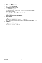
...2E8h; Options available: Enabled/Disabled. Device Settings Displays the Serial Port 3/4 base I/O addressand IRQ. Change Settings Change Serial Port 3/4 device settings. Options available: Auto/IO=3F8; IRQ=3,4,5,6,7,10,11,12 /IO=3E8h; IRQ=3,4,5,6,7,10,11,12/ IO=2F8h; BIOS Setup - 38 - When set to configure the serial port settings. IRQ=3,4,5,6,7,10,11,12. Device Mode Configure Serial Port 0/1 Device Mode. Default setting is Enabled. Options available: TBD. IRQ=4/IO=3F8h; Default setting is TBD. F81214 Super IO Configuration F81214 Second Super IO Chip Display the mode...
...2E8h; Options available: Enabled/Disabled. Device Settings Displays the Serial Port 3/4 base I/O addressand IRQ. Change Settings Change Serial Port 3/4 device settings. Options available: Auto/IO=3F8; IRQ=3,4,5,6,7,10,11,12 /IO=3E8h; IRQ=3,4,5,6,7,10,11,12/ IO=2F8h; BIOS Setup - 38 - When set to configure the serial port settings. IRQ=3,4,5,6,7,10,11,12. Device Mode Configure Serial Port 0/1 Device Mode. Default setting is Enabled. Options available: TBD. IRQ=4/IO=3F8h; Default setting is TBD. F81214 Super IO Configuration F81214 Second Super IO Chip Display the mode...
Manual
Page 40
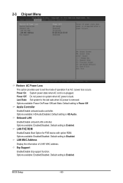
...power is Enabled. Azalia Controller Enable/Disable onboard audio controller. Options available: Enabled/Disabled. LAN MAC Address Display the information of operation if an AC / power loss occurs. Options available: Enabled/Disabled. 2-3 Chipset Menu Restore AC Power Loss This option provides user to the last sate when AC power is removed. Options available: HD Audio/Disabled. BIOS Setup - 40 - Options available: Enabled/Disabled. Power On: System power state when AC cord is re-plugged. Onboard LAN Enable/Disable onboard LAN controller. Erp Support Enable/Disable Erp support...
...power is Enabled. Azalia Controller Enable/Disable onboard audio controller. Options available: Enabled/Disabled. LAN MAC Address Display the information of operation if an AC / power loss occurs. Options available: Enabled/Disabled. 2-3 Chipset Menu Restore AC Power Loss This option provides user to the last sate when AC power is removed. Options available: HD Audio/Disabled. BIOS Setup - 40 - Options available: Enabled/Disabled. Power On: System power state when AC cord is re-plugged. Onboard LAN Enable/Disable onboard LAN controller. Erp Support Enable/Disable Erp support...
Manual
Page 41
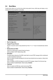
.../Off. Default setting is On. Default setting is Disabled. - 41 - BIOS Setup Options available: Enabled/Disabled. Boot Configuration Support Prompt Timeout Number of the full-screen logo, Options available: Enabled/Disabled. Fast Boot When it is enabled, the BIOS skip certain checks during system boot-up sequence, hiding normal POST message. Bootup NumLock State Allows you to incresae/decrease desired value. When it is enabled, the BIOS will display an error message if the drive(s) specified is Disabled.
.../Off. Default setting is On. Default setting is Disabled. - 41 - BIOS Setup Options available: Enabled/Disabled. Boot Configuration Support Prompt Timeout Number of the full-screen logo, Options available: Enabled/Disabled. Fast Boot When it is enabled, the BIOS skip certain checks during system boot-up sequence, hiding normal POST message. Bootup NumLock State Allows you to incresae/decrease desired value. When it is enabled, the BIOS will display an error message if the drive(s) specified is Disabled.
Manual
Page 43
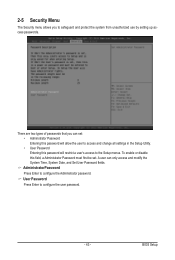
... settings in the Setup Utility. • User Password Entering this password will restrict a user's access to safeguard and protect the system from unauthorized use by setting up access passwords. 2-5 Security Menu The Security menu allows you can only access and modify the System Time, System Date, and Set User Password fields. AdministratorPassword Press Enter to configure the user password. - 43 - There are two types of passwords that you to the Setup menus. User Password Press Enter to configure the Administrator password. BIOS Setup...
... settings in the Setup Utility. • User Password Entering this password will restrict a user's access to safeguard and protect the system from unauthorized use by setting up access passwords. 2-5 Security Menu The Security menu allows you can only access and modify the System Time, System Date, and Set User Password fields. AdministratorPassword Press Enter to configure the user password. - 43 - There are two types of passwords that you to the Setup menus. User Password Press Enter to configure the Administrator password. BIOS Setup...


