Manual
Page 1
M5NM1I Intel® Atom™ D2500/D2550/D2560 processor motherboard User's Manual Rev. 1001
M5NM1I Intel® Atom™ D2500/D2550/D2560 processor motherboard User's Manual Rev. 1001

Manual
Page 3
Table of Contents Box Contents...4 M5NM1I Motherboard Layout 5 Chapter 1 Hardware Installation 7 1-1 Installation Precautions 7 1-2 Product Specifications 8 1-3 Installing the Memory 10 1-3-1 Dual Channel Memory Configuration 10 1-3-2 Installing a Memory 11 1-4 Back Panel Connectors 12 1-5 Internal ...
Table of Contents Box Contents...4 M5NM1I Motherboard Layout 5 Chapter 1 Hardware Installation 7 1-1 Installation Precautions 7 1-2 Product Specifications 8 1-3 Installing the Memory 10 1-3-1 Dual Channel Memory Configuration 10 1-3-2 Installing a Memory 11 1-4 Back Panel Connectors 12 1-5 Internal ...

Manual
Page 4
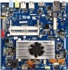
Box Contents M5NM1I motherboard Driver CD Two SATA cables I/O Shield • The box contents above are subject to change without notice. • The motherboard image is for reference only and the actual items shall depend on the product package you obtain. The box contents are for reference only. - 4 -
Box Contents M5NM1I motherboard Driver CD Two SATA cables I/O Shield • The box contents above are subject to change without notice. • The motherboard image is for reference only and the actual items shall depend on the product package you obtain. The box contents are for reference only. - 4 -
Manual
Page 5
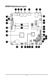
M5NM1I Motherboard Layout 123 4 5 67 34 33 32 31 30 29 28 27 8 9 10 36 35 11 12 13 14 15 17 16 18 26 25 24 23 22 21 20 19 - 5 -
M5NM1I Motherboard Layout 123 4 5 67 34 33 32 31 30 29 28 27 8 9 10 36 35 11 12 13 14 15 17 16 18 26 25 24 23 22 21 20 19 - 5 -

Manual
Page 7
...the power supply has been turned off. • Before turning on the computer power during the installation process can become damaged as a motherboard, CPU or memory. These stickers are required for warranty validation. • Always remove the AC power by your hands dry and first... touch a metal object to eliminate static electricity. • Prior to installing the motherboard, please have it on top of the product, please consult a certified computer technician. - 7 - Prior to installation, carefully read the user's manual...
...the power supply has been turned off. • Before turning on the computer power during the installation process can become damaged as a motherboard, CPU or memory. These stickers are required for warranty validation. • Always remove the AC power by your hands dry and first... touch a metal object to eliminate static electricity. • Prior to installing the motherboard, please have it on top of the product, please consult a certified computer technician. - 7 - Prior to installation, carefully read the user's manual...
Manual
Page 10
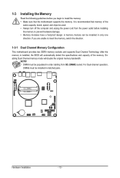
... starting from the power outlet before you are unable to insert the memory, switch the direction. 1-3-1 Dual Channel Memory Configuration This motherboard provides two DDR3 memory sockets and supports Dual Channel Technology. SO_DIMM2 SO_DIMM1 Hardware Installation - 10 - NOTE! • DIMM must be...8226; Always turn off the computer and unplug the power cord from SO_DIMM2 socket. After the memory is recommended that the motherboard supports the memory. Enabling Dual Channel memory mode will automatically detect the specifications and capacity of the same capacity, brand, ...
... starting from the power outlet before you are unable to insert the memory, switch the direction. 1-3-1 Dual Channel Memory Configuration This motherboard provides two DDR3 memory sockets and supports Dual Channel Technology. SO_DIMM2 SO_DIMM1 Hardware Installation - 10 - NOTE! • DIMM must be...8226; Always turn off the computer and unplug the power cord from SO_DIMM2 socket. After the memory is recommended that the motherboard supports the memory. Enabling Dual Channel memory mode will automatically detect the specifications and capacity of the same capacity, brand, ...
Manual
Page 11
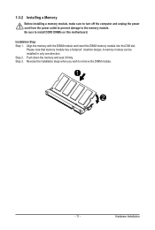
... DIMM module and insert the DIMM memory module into the DIM slot. Reverse the installation steps when you wish to install DDR3 DIMMs on this motherboard. 1-3-2 Installing a Memory Before installing a memory module, make sure to turn off the computer and unplug the power cord from the power outlet to prevent damage...
... DIMM module and insert the DIMM memory module into the DIM slot. Reverse the installation steps when you wish to install DDR3 DIMMs on this motherboard. 1-3-2 Installing a Memory Before installing a memory module, make sure to turn off the computer and unplug the power cord from the power outlet to prevent damage...

Manual
Page 12
... AC3, DTS and 2-channel-LPCM formats. (AC3 and DTS require the use of the LAN port LEDs. Do not rock it straight out from the motherboard. • When removing the cable, pull it side to side to this port. Line In Jack (Blue) The default line in devices such as a USB...
... AC3, DTS and 2-channel-LPCM formats. (AC3 and DTS require the use of the LAN port LEDs. Do not rock it straight out from the motherboard. • When removing the cable, pull it side to side to this port. Line In Jack (Blue) The default line in devices such as a USB...
Manual
Page 13
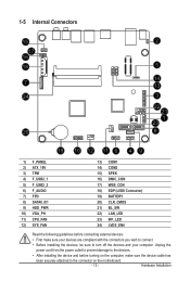
..., make sure your devices are compliant with the connectors you wish to connect. • Before installing the devices, be sure to the connector on the motherboard. - 13 - Hardware Installation Unplug the power cord from the power outlet to prevent damage to the devices. • After installing the device and before connecting...
..., make sure your devices are compliant with the connectors you wish to connect. • Before installing the devices, be sure to the connector on the motherboard. - 13 - Hardware Installation Unplug the power cord from the power outlet to prevent damage to the devices. • After installing the device and before connecting...
Manual
Page 17
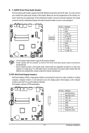
...AC'97 audio. Most laptops, LCD computer monitors and LCD TVs use this header. Incorrect connection between the module connector and the motherboard header will be present on both of the front and back panel audio connections simultaneously. • Some chassis provide a front ... the chassis manufacturer. 7) FPD (Flat Panel Display Headers) Flat Panel Display (FPD)is a high-speed interface connecting the output of the motherboard header. For information about connecting the front panel audio module that has separated connectors on each wire instead of a single plug. Definition 1 ...
...AC'97 audio. Most laptops, LCD computer monitors and LCD TVs use this header. Incorrect connection between the module connector and the motherboard header will be present on both of the front and back panel audio connections simultaneously. • Some chassis provide a front ... the chassis manufacturer. 7) FPD (Flat Panel Display Headers) Flat Panel Display (FPD)is a high-speed interface connecting the output of the motherboard header. For information about connecting the front panel audio module that has separated connectors on each wire instead of a single plug. Definition 1 ...

Manual
Page 19
Hardware Installation The motherboard supports CPU fan speed control, which requires the use of a CPU fan with fan speed control design. Do not place a jumper cap on the headers. - ... Definition RED DDCSDA GND DDSCL GREEN GND GREEN DDC Clock BLUE DDC Data NC NC 11/12) CPU_FAN/SYS_FAN (CPU Fan/System Fan Headers) The motherboard has a 4-pin CPU fan header (CPU_FAN) and a 4-pin System fan header (SYS_FAN) header. When connecting a fan cable, be sure to connect it is the ground...
Hardware Installation The motherboard supports CPU fan speed control, which requires the use of a CPU fan with fan speed control design. Do not place a jumper cap on the headers. - ... Definition RED DDCSDA GND DDSCL GREEN GND GREEN DDC Clock BLUE DDC Data NC NC 11/12) CPU_FAN/SYS_FAN (CPU Fan/System Fan Headers) The motherboard has a 4-pin CPU fan header (CPU_FAN) and a 4-pin System fan header (SYS_FAN) header. When connecting a fan cable, be sure to connect it is the ground...
Manual
Page 23
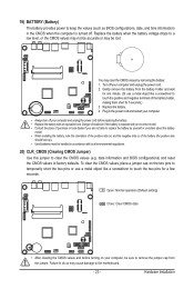
... and unplug the power cord before turning on the two pins to temporarily short the two pins or use a metal object like a screwdriver to the motherboard. - 23 - Plug in accordance with an equivalent one minute. (Or use a metal object like a screwdriver to touch the positive and negative terminals of the battery...
... and unplug the power cord before turning on the two pins to temporarily short the two pins or use a metal object like a screwdriver to the motherboard. - 23 - Plug in accordance with an equivalent one minute. (Or use a metal object like a screwdriver to touch the positive and negative terminals of the battery...

Manual
Page 26
...default values. (Refer to the "Load Optimized Defaults" section in this chapter or introductions of the battery/ clearing CMOS jumper in the CMOS on the motherboard. When the power is turned off, the battery on . • BIOS flashing is potentially risky, if you don't flash the BIOS. Its major... functions include conducting the Power-On Self-Test (POST) during the POST when the power is turned on the motherboard supplies the necessary power to the CMOS to keep the configuration values in system malfunction. • It is recommended that you do not encounter ...
...default values. (Refer to the "Load Optimized Defaults" section in this chapter or introductions of the battery/ clearing CMOS jumper in the CMOS on the motherboard. When the power is turned off, the battery on . • BIOS flashing is potentially risky, if you don't flash the BIOS. Its major... functions include conducting the Power-On Self-Test (POST) during the POST when the power is turned on the motherboard supplies the necessary power to the CMOS to keep the configuration values in system malfunction. • It is recommended that you do not encounter ...
Manual
Page 41
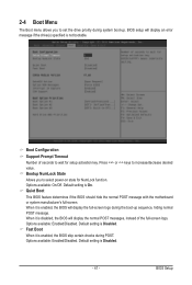
... Disabled. - 41 - Default setting is Disabled. BIOS Setup Quiet Boot This BIOS feature determines if the BIOS should hide the normal POST message with the motherboard or system manufacturer's full-screen. 2-4 Boot Menu The Boot menu allows you to incresae/decrease desired value. Fast Boot When it is enabled, the BIOS...
... Disabled. - 41 - Default setting is Disabled. BIOS Setup Quiet Boot This BIOS feature determines if the BIOS should hide the normal POST message with the motherboard or system manufacturer's full-screen. 2-4 Boot Menu The Boot menu allows you to incresae/decrease desired value. Fast Boot When it is enabled, the BIOS...


