Manual
Page 3
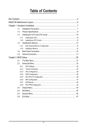
... Box Contents...4 MSQ77DI Motherboard Layout 5 Chapter 1 Hardware Installation 7 1-1 Installation Precautions 7 1-2 Product Specifications 8 1-3 Installing the CPU and CPU Cooler 10 1-3-1 Installing the CPU...10 1-3-2 Installing the CPU Cooler 12 1-4 Installing the Memory 13 1-4-1 Dual Channel Memory Configuration 13 1-4-2 Installing a Memory 14 1-5 Back Panel Connectors 15 1-6 Internal Connectors 17 Chapter 2 BIOS Setup 29 2-1 The Main Menu 31 2-2 Advanced Menu 33 2-2-1 ACPI Settings...34 2-2-2 Trusted Computing 35 2-2-3 CPU Configuration 36 2-2-4 SATA Configuration 38...
... Box Contents...4 MSQ77DI Motherboard Layout 5 Chapter 1 Hardware Installation 7 1-1 Installation Precautions 7 1-2 Product Specifications 8 1-3 Installing the CPU and CPU Cooler 10 1-3-1 Installing the CPU...10 1-3-2 Installing the CPU Cooler 12 1-4 Installing the Memory 13 1-4-1 Dual Channel Memory Configuration 13 1-4-2 Installing a Memory 14 1-5 Back Panel Connectors 15 1-6 Internal Connectors 17 Chapter 2 BIOS Setup 29 2-1 The Main Menu 31 2-2 Advanced Menu 33 2-2-1 ACPI Settings...34 2-2-2 Trusted Computing 35 2-2-3 CPU Configuration 36 2-2-4 SATA Configuration 38...
Manual
Page 6
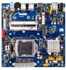
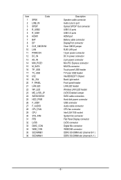
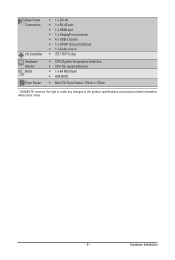
... Out connector USB 3.0 ports USB 3.0 ports HDMI port Battery cable connector DisplayPort connector Clear CMOS jumper RJ45 LAN port 12-pin power connector DC In power connector 2 pin power connector Mini PCi Express connector MSATA connector Touch panel USB header TV tuner USB header Intel BD82Q77 Chipset Back Light switch Front panel header LAN LED header Wireless LAN LED header LVDS Enabled Jumper SATA cable connectors Hard disk power connector USB connector Audio cable connector CPU fan connector Intel LGA1155 socket System fan connector Flat Panel Display connector LVDS connector Digital...
... Out connector USB 3.0 ports USB 3.0 ports HDMI port Battery cable connector DisplayPort connector Clear CMOS jumper RJ45 LAN port 12-pin power connector DC In power connector 2 pin power connector Mini PCi Express connector MSATA connector Touch panel USB header TV tuner USB header Intel BD82Q77 Chipset Back Light switch Front panel header LAN LED header Wireless LAN LED header LVDS Enabled Jumper SATA cable connectors Hard disk power connector USB connector Audio cable connector CPU fan connector Intel LGA1155 socket System fan connector Flat Panel Display connector LVDS connector Digital...

Manual
Page 7
... the motherboard, do not remove or break motherboard S/N (Serial Number) sticker or warranty sticker provided by unplugging the power cord from the motherboard, make sure the power supply has been turned off. • Before turning on the motherboard, make sure the power supply voltage has been set according to the local voltage standard. • Before using the product, please verify that all cables and power connectors of your dealer. Hardware Installation...
... the motherboard, do not remove or break motherboard S/N (Serial Number) sticker or warranty sticker provided by unplugging the power cord from the motherboard, make sure the power supply has been turned off. • Before turning on the motherboard, make sure the power supply voltage has been set according to the local voltage standard. • Before using the product, please verify that all cables and power connectors of your dealer. Hardware Installation...
Manual
Page 8
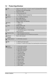
...4GB x 2) Dual channel architecture Support for Intel® Core™ i7, Core™i5, Core™i3 processors/Intel® Pentium® processors in Intel® processor 2 x SATA 6Gb/s connectors USB ŠŠ 4 x USB 3.0 ports (back panel) ŠŠ 5 x USB 2.0/1.1 headers (Card reader/Touch panel/webcam and other devices) Internal Connectors ŠŠ 1 x 12-pin power connector ŠŠ 1 x 2-pin power connector ŠŠ 2 x SATA 6Gb/s connectors ŠŠ 1 x HDD power connector ŠŠ 1 x CPU fan header ŠŠ 1 x System fan header ŠŠ...
...4GB x 2) Dual channel architecture Support for Intel® Core™ i7, Core™i5, Core™i3 processors/Intel® Pentium® processors in Intel® processor 2 x SATA 6Gb/s connectors USB ŠŠ 4 x USB 3.0 ports (back panel) ŠŠ 5 x USB 2.0/1.1 headers (Card reader/Touch panel/webcam and other devices) Internal Connectors ŠŠ 1 x 12-pin power connector ŠŠ 1 x 2-pin power connector ŠŠ 2 x SATA 6Gb/s connectors ŠŠ 1 x HDD power connector ŠŠ 1 x CPU fan header ŠŠ 1 x System fan header ŠŠ...
Manual
Page 9
... port ŠŠ 1 x HDMI port ŠŠ 1 x DisplayPort connector ŠŠ 4 x USB 3.0 ports ŠŠ 1 x SPDIF Out port (Optical) ŠŠ 1 x Audio Line In ŠŠ iTE IT8773 chip ŠŠ CPU/System temperature detection ŠŠ CPU fan speed detection ŠŠ 1 x 64 Mbit flash ŠŠ AMI BIOS ŠŠ Mini ITX Form Factor; 170cm x 170cm * GIGABYTE reserves the right to make any changes to the product specifications...
... port ŠŠ 1 x HDMI port ŠŠ 1 x DisplayPort connector ŠŠ 4 x USB 3.0 ports ŠŠ 1 x SPDIF Out port (Optical) ŠŠ 1 x Audio Line In ŠŠ iTE IT8773 chip ŠŠ CPU/System temperature detection ŠŠ CPU fan speed detection ŠŠ 1 x 64 Mbit flash ŠŠ AMI BIOS ŠŠ Mini ITX Form Factor; 170cm x 170cm * GIGABYTE reserves the right to make any changes to the product specifications...
Manual
Page 10
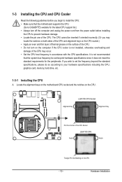
... that the motherboard supports the CPU. (Go to GIGABYTE's website for the peripherals. If you wish to set beyond the standard specifications, please do so according to your hardware specifications including the CPU, graphics card, memory, hard drive, etc. 1-3-1 Installing the CPU A. 1-3 Installing the CPU and CPU Cooler Read the following guidelines before installing the CPU to prevent hardware damage. • Locate the pin one of the CPU. Hardware Installation LGA1155 CPU Socket Alignment Key Alignment Key Pin One...
... that the motherboard supports the CPU. (Go to GIGABYTE's website for the peripherals. If you wish to set beyond the standard specifications, please do so according to your hardware specifications including the CPU, graphics card, memory, hard drive, etc. 1-3-1 Installing the CPU A. 1-3 Installing the CPU and CPU Cooler Read the following guidelines before installing the CPU to prevent hardware damage. • Locate the pin one of the CPU. Hardware Installation LGA1155 CPU Socket Alignment Key Alignment Key Pin One...
Manual
Page 11
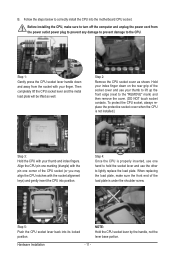
... away from the power outlet power plug to prevent any damage to prevent damage to correctly install the CPU into the motherboard CPU socket. Step 5: Push the CPU socket lever back into position. Follow the steps below to the CPU. Align the CPU pin one marking (triangle) with the pin one hand to hold the socket lever and use the other to the "REMOVE" mark) and then...
... away from the power outlet power plug to prevent any damage to prevent damage to correctly install the CPU into the motherboard CPU socket. Step 5: Push the CPU socket lever back into position. Follow the steps below to the CPU. Align the CPU pin one marking (triangle) with the pin one hand to hold the socket lever and use the other to the "REMOVE" mark) and then...

Manual
Page 13
... brand, speed, and chips be populated in order starting from the power outlet before installing the memory to insert the memory, switch the direction. 1-4-1 Dual Channel Memory Configuration This motherboard provides two DDR3 memory sockets and supports Dual Channel Technology. For Dual-channel operation, DIMMs must be used for optimum performance. 1-4 Installing the Memory Read the following guidelines before installing the memory in Dual Channel mode. 1. When enabling Dual Channel mode with two memory modules, it is installed, the BIOS will double the original memory bandwidth.
... brand, speed, and chips be populated in order starting from the power outlet before installing the memory to insert the memory, switch the direction. 1-4-1 Dual Channel Memory Configuration This motherboard provides two DDR3 memory sockets and supports Dual Channel Technology. For Dual-channel operation, DIMMs must be used for optimum performance. 1-4 Installing the Memory Read the following guidelines before installing the memory in Dual Channel mode. 1. When enabling Dual Channel mode with two memory modules, it is installed, the BIOS will double the original memory bandwidth.
Manual
Page 14
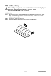
... DIMM memory module into the DIM slot. Hardware Installation Installation Step: Step 1. Step 2. Be sure to remove the DIMM module. 1 2 - 14 - A memory module can be installed In only one direction. Push down the memory and seat it firmly. Please note that memory module has a foolproof insertion design. 1-4-2 Installing a Memory Before installing a memory module, make sure to turn off the computer and unplug the power cord...
... DIMM memory module into the DIM slot. Hardware Installation Installation Step: Step 1. Step 2. Be sure to remove the DIMM module. 1 2 - 14 - A memory module can be installed In only one direction. Push down the memory and seat it firmly. Please note that memory module has a foolproof insertion design. 1-4-2 Installing a Memory Before installing a memory module, make sure to turn off the computer and unplug the power cord...

Manual
Page 15
... is primarily used to connect a video source to a display device such as a computer monitor, though it can support a maximum resolution of the LAN port LEDs. USB 3.0 Ports The USB port supports the USB 3.0 specification. Use this feature, ensure that supports digital optical audio. Line In Jack (Blue) The default line in devices such as a USB keyboard/mouse, USB printer, USB flash drive and etc. Refer the figures below for details.), and enter BIOS Setup, then set Onboard VGA output connect to D-SUB/ HDMI under Advanced BIOS Features...
... is primarily used to connect a video source to a display device such as a computer monitor, though it can support a maximum resolution of the LAN port LEDs. USB 3.0 Ports The USB port supports the USB 3.0 specification. Use this feature, ensure that supports digital optical audio. Line In Jack (Blue) The default line in devices such as a USB keyboard/mouse, USB printer, USB flash drive and etc. Refer the figures below for details.), and enter BIOS Setup, then set Onboard VGA output connect to D-SUB/ HDMI under Advanced BIOS Features...
Manual
Page 21
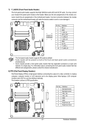
... panel audio header supports HD audio by default. • Audio signals will make the device unable to this interface internally. Most laptops, LCD computer monitors and LCD TVs use this header. Hardware Installation You may connect your chassis front panel audio module to work or even damage it. Pin No. Incorrect connection between the module connector and the motherboard header will be present on each wire instead of a single plug. For information about connecting the front panel audio...
... panel audio header supports HD audio by default. • Audio signals will make the device unable to this interface internally. Most laptops, LCD computer monitors and LCD TVs use this header. Hardware Installation You may connect your chassis front panel audio module to work or even damage it. Pin No. Incorrect connection between the module connector and the motherboard header will be present on each wire instead of a single plug. For information about connecting the front panel audio...
Manual
Page 22
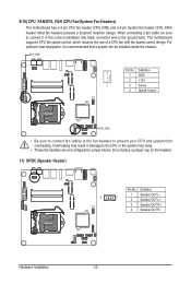
... connector wire is recommended that a system fan be sure to connect it is the ground wire). Hardware Installation - 22 - Do not place a jumper cap on the headers. 11) SPEK (Speaker Header) Pin No. The motherboard supports CPU fan speed control, which requires the use of a CPU fan with fan speed control design. Most fan headers possess a foolproof insertion design. Definition 1 Speaker OUT L- 4 1 2 Speaker OUT L+ 3 Speaker OUT R+ 4 Speaker OUT R- When connecting a fan cable, be installed inside the chassis. SYS_FAN Pin No. 9/10) CPU_FAN/SYS_FAN (CPU Fan/System Fan...
... connector wire is recommended that a system fan be sure to connect it is the ground wire). Hardware Installation - 22 - Do not place a jumper cap on the headers. 11) SPEK (Speaker Header) Pin No. The motherboard supports CPU fan speed control, which requires the use of a CPU fan with fan speed control design. Most fan headers possess a foolproof insertion design. Definition 1 Speaker OUT L- 4 1 2 Speaker OUT L+ 3 Speaker OUT R+ 4 Speaker OUT R- When connecting a fan cable, be installed inside the chassis. SYS_FAN Pin No. 9/10) CPU_FAN/SYS_FAN (CPU Fan/System Fan...
Manual
Page 28
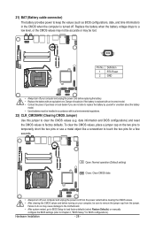
... pins for BIOS configurations). To clear the CMOS values, place a jumper cap on your computer, be sure to remove the jumper cap from the power outlet before clearing the CMOS values. • After clearing the CMOS values and before replacing the battery. • Replace the battery with local environmental regulations. 22) CLR_CMOSHW (Clearing CMOS Jumper) Use this jumper to clear the CMOS values (e.g. Open: Normal operation (Default setting) Close: Clear CMOS data • Always turn off . 21) BAT (Battery cable connector) The battery...
... pins for BIOS configurations). To clear the CMOS values, place a jumper cap on your computer, be sure to remove the jumper cap from the power outlet before clearing the CMOS values. • After clearing the CMOS values and before replacing the battery. • Replace the battery with local environmental regulations. 22) CLR_CMOSHW (Clearing CMOS Jumper) Use this jumper to clear the CMOS values (e.g. Open: Normal operation (Default setting) Close: Clear CMOS data • Always turn off . 21) BAT (Battery cable connector) The battery...
Manual
Page 29
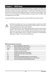
When the power is turned off, the battery on the motherboard supplies the necessary power to the CMOS to select the screen Execute command or enter the submenu Main Menu: Exit the BIOS Setup program Submenus: Exit current submenu Increase the numeric value or make changes Decrease the numeric value or make changes General Help Restore the previous BIOS settings for the current submenus Load the Optimized BIOS default settings for the...
When the power is turned off, the battery on the motherboard supplies the necessary power to the CMOS to select the screen Execute command or enter the submenu Main Menu: Exit the BIOS Setup program Submenus: Exit current submenu Increase the numeric value or make changes Decrease the numeric value or make changes General Help Restore the previous BIOS settings for the current submenus Load the Optimized BIOS default settings for the...
Manual
Page 30
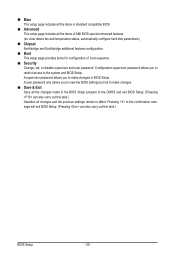
...: Auto detect fan and temperature status, automatically configure hard disk parameters.) Chipset Northbridge and Southbridge additional features configuration. Boot This setup page provides items for configuration of boot sequence. Security Change, set, or disable supervisor and user password. Pressing to make changes in effect. A supervisor password allows you to view the BIOS settings but not to the confirmation message will exit BIOS Setup. (Pressing can also carry out this task.) BIOS Setup...
...: Auto detect fan and temperature status, automatically configure hard disk parameters.) Chipset Northbridge and Southbridge additional features configuration. Boot This setup page provides items for configuration of boot sequence. Security Change, set, or disable supervisor and user password. Pressing to make changes in effect. A supervisor password allows you to view the BIOS settings but not to the confirmation message will exit BIOS Setup. (Pressing can also carry out this task.) BIOS Setup...
Manual
Page 38
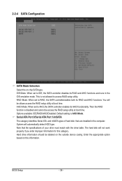
...device casing. BIOS Setup - 38 - Then the RAID function is AHCI Mode. Note that are installed in the IDE emulation mode. The hard disk will be allows access the RAID setup utility at boot time. Default setting is disabled and cannot be labeled on this category. Hard drive information should be access the RAID setup utility at boot time. This is not allowed to AHCI,the SATA controller enables its RAID and AHCI functions and runs in the computer. RAID Mode: When set to access RAID setup utility. Options available: IDE/RAID/AHCI/Disabled. 2-2-4 SATA Configuration...
...device casing. BIOS Setup - 38 - Then the RAID function is AHCI Mode. Note that are installed in the IDE emulation mode. The hard disk will be allows access the RAID setup utility at boot time. Default setting is disabled and cannot be labeled on this category. Hard drive information should be access the RAID setup utility at boot time. This is not allowed to AHCI,the SATA controller enables its RAID and AHCI functions and runs in the computer. RAID Mode: When set to access RAID setup utility. Options available: IDE/RAID/AHCI/Disabled. 2-2-4 SATA Configuration...
Manual
Page 42
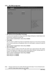
... in response to processor load. Options available: Enabled/Disabled. Default setting for quad-core processors. For more enhanced power-saving state than C1. 2-2-8 CPU PPM Configuration EIST (Enhanced Intel SpeedStep Technology) Conventional Intel SpeedStep Technology switches both voltage and frequency in tandem between high and low levels in system halt state. Options available: Enabled/Disabled. Default setting is Enabled. Turbo Mode When this feature. Default setting is Enabled. Default setting for C3 is enabled, the processor can dynamically overclock one or two of...
... in response to processor load. Options available: Enabled/Disabled. Default setting for quad-core processors. For more enhanced power-saving state than C1. 2-2-8 CPU PPM Configuration EIST (Enhanced Intel SpeedStep Technology) Conventional Intel SpeedStep Technology switches both voltage and frequency in tandem between high and low levels in system halt state. Options available: Enabled/Disabled. Default setting is Enabled. Turbo Mode When this feature. Default setting is Enabled. Default setting for C3 is enabled, the processor can dynamically overclock one or two of...
Manual
Page 43
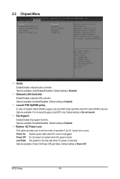
2-3 Chipset Menu Azalia Enable/Disable onboard audio controller. Onboard LAN Controller Enable/Disable onboard LAN controller. Options available: Auto/Enabled/Disabled. Options available: Enabled/Disabled. Power Off: Do not power on system when AC power is removed. Last State: Set system to launch. Launch PXE OpROM policy In case of operation if an AC / power loss occurs. Default setting is Enabled. Restore AC Power Loss This option provides user to set the mode of multiple Option ROMs (Legacy only and UEFI Only) specifies what PCI option ROM to the last sate when ...
2-3 Chipset Menu Azalia Enable/Disable onboard audio controller. Onboard LAN Controller Enable/Disable onboard LAN controller. Options available: Auto/Enabled/Disabled. Options available: Enabled/Disabled. Power Off: Do not power on system when AC power is removed. Last State: Set system to launch. Launch PXE OpROM policy In case of operation if an AC / power loss occurs. Default setting is Enabled. Restore AC Power Loss This option provides user to set the mode of multiple Option ROMs (Legacy only and UEFI Only) specifies what PCI option ROM to the last sate when ...
Manual
Page 44
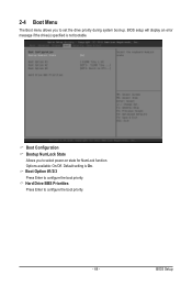
Default setting is not bootable. BIOS Setup Boot Configuration Bootup NumLock State Allows you to configure the boot priority. - 44 - Boot Option #1/2/3 Press Enter to select power-on state for NumLock function. BIOS setup will display an error message if the drive(s) specified is On. Hard Drive BBS Priorities Press Enter to set the drive priority during system boot-up. Options available: On/Off. 2-4 Boot Menu The Boot menu allows you to configure the boot priority.
Default setting is not bootable. BIOS Setup Boot Configuration Bootup NumLock State Allows you to configure the boot priority. - 44 - Boot Option #1/2/3 Press Enter to select power-on state for NumLock function. BIOS setup will display an error message if the drive(s) specified is On. Hard Drive BBS Priorities Press Enter to set the drive priority during system boot-up. Options available: On/Off. 2-4 Boot Menu The Boot menu allows you to configure the boot priority.

Manual
Page 45
... Password Entering this password will allow the user to access and change all settings in the Setup Utility. • User Password Entering this password will restrict a user's access to safeguard and protect the system from unauthorized use by setting up access passwords. Intel ME Function Enable/Disable the Intel ME support function. User Password Press Enter to configure the Administrator password. A user can set . AdministratorPassword Press Enter to configure the user password. BIOS Setup - 45 - Options available: Enabled/Disabled. There are two types of passwords...
... Password Entering this password will allow the user to access and change all settings in the Setup Utility. • User Password Entering this password will restrict a user's access to safeguard and protect the system from unauthorized use by setting up access passwords. Intel ME Function Enable/Disable the Intel ME support function. User Password Press Enter to configure the Administrator password. A user can set . AdministratorPassword Press Enter to configure the user password. BIOS Setup - 45 - Options available: Enabled/Disabled. There are two types of passwords...


