Manual
Page 1
MW50-SV0 LGA2011 sockets R3 motherboard for Intel® E5-1600 V3/E5-2600 V3 series processor User's Manual Rev. 1001
MW50-SV0 LGA2011 sockets R3 motherboard for Intel® E5-1600 V3/E5-2600 V3 series processor User's Manual Rev. 1001
Manual
Page 3
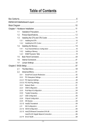
Table of Contents Box Contents...6 MW50-SV0 Motherboard Layout 7 Block Diagram...10 Chapter 1 Hardware Installation 11 1-1 Installation Precautions 11 1-2 Product Specifications 12 1-3 Installing the CPU and CPU Cooler 14 1-3-1 Installing the CPU...14 1-3-2 ...
Table of Contents Box Contents...6 MW50-SV0 Motherboard Layout 7 Block Diagram...10 Chapter 1 Hardware Installation 11 1-1 Installation Precautions 11 1-2 Product Specifications 12 1-3 Installing the CPU and CPU Cooler 14 1-3-1 Installing the CPU...14 1-3-2 ...
Manual
Page 6
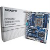
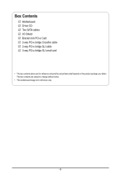
Box Contents Motherboard Driver CD Two SATA cables I/O Shield Bracket mini PCI-e Card 2-way PCI-e bridge Crossfire cable 2-way PCI-e bridge SLI cable 3-way PCI-e bridge SLI small card • The box contents above are subject to change without notice. • The motherboard image is for reference only and the actual items shall depend on the product package you obtain. The box contents are for reference only. - 6 -
Box Contents Motherboard Driver CD Two SATA cables I/O Shield Bracket mini PCI-e Card 2-way PCI-e bridge Crossfire cable 2-way PCI-e bridge SLI cable 3-way PCI-e bridge SLI small card • The box contents above are subject to change without notice. • The motherboard image is for reference only and the actual items shall depend on the product package you obtain. The box contents are for reference only. - 6 -
Manual
Page 7
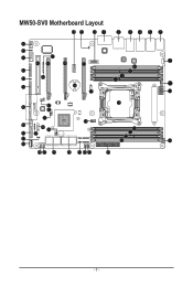
MW50-SV0 Motherboard Layout 50 51 52 1 2 34 5 6 44 43 42 47 45 48 49 53 7 8 41 9 40 46 10 11 12 39 54 55 13 14 38 37 36 35 32 34 26 31 33 30 29 56 16 17 18 19 15 28 27 25 24 23 22 21 20 - 7 -
MW50-SV0 Motherboard Layout 50 51 52 1 2 34 5 6 44 43 42 47 45 48 49 53 7 8 41 9 40 46 10 11 12 39 54 55 13 14 38 37 36 35 32 34 26 31 33 30 29 56 16 17 18 19 15 28 27 25 24 23 22 21 20 - 7 -
Manual
Page 9
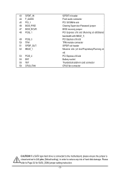
... x16 slot Battery socket Thunderbolt addin-in order to Page 32 for SATA_DOM jumper setting instruction. - 9 - If a SATA type hard drive is connected to the motherboard, please ensure the jumper is closed and set to 2-3 pins (Default setting), in card connector CPU0 fan connector CAUTION! Please refer to reduce any risk...
... x16 slot Battery socket Thunderbolt addin-in order to Page 32 for SATA_DOM jumper setting instruction. - 9 - If a SATA type hard drive is connected to the motherboard, please ensure the jumper is closed and set to 2-3 pins (Default setting), in card connector CPU0 fan connector CAUTION! Please refer to reduce any risk...
Manual
Page 11
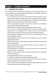
...result of the product, please consult a certified computer technician. - 11 - Hardware Installation Chapter 1 Hardware Installation 1-1 Installation Precautions The motherboard contains numerous delicate electronic circuits and components which can lead to damage to system components as well as physical harm to the user. ...AC power by your hands dry and first touch a metal object to eliminate static electricity. • Prior to installing the motherboard, please have it on top of an antistatic pad or within an electrostatic shielding container. • Before unplugging the power ...
...result of the product, please consult a certified computer technician. - 11 - Hardware Installation Chapter 1 Hardware Installation 1-1 Installation Precautions The motherboard contains numerous delicate electronic circuits and components which can lead to damage to system components as well as physical harm to the user. ...AC power by your hands dry and first touch a metal object to eliminate static electricity. • Prior to installing the motherboard, please have it on top of an antistatic pad or within an electrostatic shielding container. • Before unplugging the power ...
Manual
Page 14
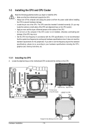
Locate the alignment keys on the motherboard CPU socket and the notches on the CPU Notch - 14 - If you begin to install the CPU: • Make sure that the system bus frequency ... be set the frequency beyond hardware specifications since it does not meet the standard requirements for the peripherals. Notch It is not recommended that the motherboard supports the CPU. • Always turn on the surface of the CPU. • Do not turn off the computer and unplug the power cord from...
Locate the alignment keys on the motherboard CPU socket and the notches on the CPU Notch - 14 - If you begin to install the CPU: • Make sure that the system bus frequency ... be set the frequency beyond hardware specifications since it does not meet the standard requirements for the peripherals. Notch It is not recommended that the motherboard supports the CPU. • Always turn on the surface of the CPU. • Do not turn off the computer and unplug the power cord from...
Manual
Page 15
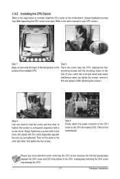
... closest to release it if the CPU is opened.) Step 4: Hold the CPU with the socket alignment keys) and carefully insert the CPU into the motherboard CPU socket. •• Before installing the CPU, make sure to turn off the computer and unplug the power cord from the power outlet to...
... closest to release it if the CPU is opened.) Step 4: Hold the CPU with the socket alignment keys) and carefully insert the CPU into the motherboard CPU socket. •• Before installing the CPU, make sure to turn off the computer and unplug the power cord from the power outlet to...
Manual
Page 17
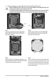
mounting screws with the mounting holes on the motherboard. Begin tightening a screw with a few turns and repeat with a screw driver. Then do the same to the other to tighten the screws in a diagonal sequence ... steps below to correctly install the CPU cooler on the Place the cooler atop the CPU, aligning the four surface of thermal grease on the motherboard. (Actual installation process may damage the CPU. - 17 - Refer to the CPU. Hardware Installation Inadequately removing the CPU cooler may differ depending the CPU cooler...
mounting screws with the mounting holes on the motherboard. Begin tightening a screw with a few turns and repeat with a screw driver. Then do the same to the other to tighten the screws in a diagonal sequence ... steps below to correctly install the CPU cooler on the Place the cooler atop the CPU, aligning the four surface of thermal grease on the motherboard. (Actual installation process may damage the CPU. - 17 - Refer to the CPU. Hardware Installation Inadequately removing the CPU cooler may differ depending the CPU cooler...
Manual
Page 18
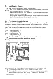
...for optimum performance. It is installed. 2. Four Channel mode cannot be enabled if only one DDR4 memory module is recommended that the motherboard supports the memory. A memory module can be installed in only one DIMM is used . • Always turn off the computer and... one direction. The four DDR4 memory sockets are unable to insert the memory, switch the direction. 1-4-1 Four Channel Memory Configuration This motherboard provides Eight DDR4 memory sockets and supports Four Channel Technology. 1-4 Installing the Memory Read the following guidelines before you are divided into ...
...for optimum performance. It is installed. 2. Four Channel mode cannot be enabled if only one DDR4 memory module is recommended that the motherboard supports the memory. A memory module can be installed in only one DIMM is used . • Always turn off the computer and... one direction. The four DDR4 memory sockets are unable to insert the memory, switch the direction. 1-4-1 Four Channel Memory Configuration This motherboard provides Eight DDR4 memory sockets and supports Four Channel Technology. 1-4 Installing the Memory Read the following guidelines before you are divided into ...
Manual
Page 19
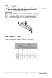
.... Be sure to lock the DIMM module. Step 2. Close the plastic clip at both edges of the DIMM slots to install DDR4 DIMMs on this motherboard. Step 3. Insert the DIMM memory module vertically into the DIMM slot, and push it down. Slot Per Channel (SPC) and DIMM Per Channel (DPC) 1 Slot...
.... Be sure to lock the DIMM module. Step 2. Close the plastic clip at both edges of the DIMM slots to install DDR4 DIMMs on this motherboard. Step 3. Insert the DIMM memory module vertically into the DIMM slot, and push it down. Slot Per Channel (SPC) and DIMM Per Channel (DPC) 1 Slot...
Manual
Page 20
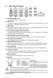
... devices. Use this port. Microphones must be used to 1 Gbps data rate. Serial Port Connects to a back panel connector, first remove the cable from the motherboard. • When removing the cable, pull it side to side to prevent an electrical short inside the cable connector.
... devices. Use this port. Microphones must be used to 1 Gbps data rate. Serial Port Connects to a back panel connector, first remove the cable from the motherboard. • When removing the cable, pull it side to side to prevent an electrical short inside the cable connector.
Manual
Page 21
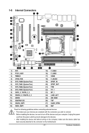
...) SPDIF_OUT 21) TPM 22) FP_1 23) BP_1 24) LAN3_ACT 25) SW_RAID 26) TBT 27) CASE_OPEN 28) BAT Read the following guidelines before turning on the motherboard. - 21 - Unplug the power cord from the power outlet to prevent damage to the devices. • After installing the device and before connecting external devices...
...) SPDIF_OUT 21) TPM 22) FP_1 23) BP_1 24) LAN3_ACT 25) SW_RAID 26) TBT 27) CASE_OPEN 28) BAT Read the following guidelines before turning on the motherboard. - 21 - Unplug the power cord from the power outlet to prevent damage to the devices. • After installing the device and before connecting external devices...
Manual
Page 22
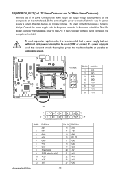
... power consumption be used that can lead to an unstable or unbootable system. If a power supply is turned off and all the components on the motherboard. Before connecting the power connector, first make sure the power supply is used (500W or greater). 1/2) ATX/P12V_AUX1 (2x4 12V Power Connector and 2x12 Main...
... power consumption be used that can lead to an unstable or unbootable system. If a power supply is turned off and all the components on the motherboard. Before connecting the power connector, first make sure the power supply is used (500W or greater). 1/2) ATX/P12V_AUX1 (2x4 12V Power Connector and 2x12 Main...
Manual
Page 23
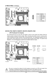
... hang. • These fan headers are not configuration jumper blocks. Do not place a jumper cap on the headers. - 23 - 3) PMBUS (PMBus connector) 1 Pin No. The motherboard supports CPU fan speed control, which requires the use of a CPU fan with fan speed control design. For optimum heat dissipation, it in damage to... is the ground wire). Definition 1 PMBus CLK 2 PMBus DATA 3 PMBus Alert 5 4 GND 5 3.3V Sense 4/5/6/7/8) CPU0_FAN/SYS_FAN0/SYS_FAN1/SYS_FAN2/SYS_FAN3 (CPU Fan/System Fan Headers) The motherboard has one 4-pin CPU fan headers, and four 4-pin system fan headers.
... hang. • These fan headers are not configuration jumper blocks. Do not place a jumper cap on the headers. - 23 - 3) PMBUS (PMBus connector) 1 Pin No. The motherboard supports CPU fan speed control, which requires the use of a CPU fan with fan speed control design. For optimum heat dissipation, it in damage to... is the ground wire). Definition 1 PMBus CLK 2 PMBus DATA 3 PMBus Alert 5 4 GND 5 3.3V Sense 4/5/6/7/8) CPU0_FAN/SYS_FAN0/SYS_FAN1/SYS_FAN2/SYS_FAN3 (CPU Fan/System Fan Headers) The motherboard has one 4-pin CPU fan headers, and four 4-pin system fan headers.
Manual
Page 26
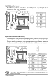
Incorrect connection between the module connector and the motherboard header will make the device unable to this header. You may connect your chassis provides an AC'97 front panel audio module. If your chassis ...; The front panel audio header supports HD audio by default. Make sure the wire assignments of the module connector match the pin assignments of the motherboard header. For purchasing the optional COM port cable, please contact the local dealer. 12 9 10 Pin No. 1 2 3 4 5 6 7 8 9 10 Definition NDCDNSIN NSOUT NDTRGND NDSRNRTSNCTSNRINo Pin 18...
Incorrect connection between the module connector and the motherboard header will make the device unable to this header. You may connect your chassis provides an AC'97 front panel audio module. If your chassis ...; The front panel audio header supports HD audio by default. Make sure the wire assignments of the module connector match the pin assignments of the motherboard header. For purchasing the optional COM port cable, please contact the local dealer. 12 9 10 Pin No. 1 2 3 4 5 6 7 8 9 10 Definition NDCDNSIN NSOUT NDTRGND NDSRNRTSNCTSNRINo Pin 18...
Manual
Page 33
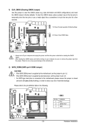
.... 1 2 3 Definition P5V SATA4 Pin7 GND - 33 - Failure to do so may cause damage to the motherboard. 2) SATA_DOM4 (SATA port 4 DOM Jumper) CAUTION! • If the SATA DOM power is supplied by the motherboard, set the jumper to pin 1-2. • If the SATA DOM power is supplied by external power, set... the jumper to pin 2-3. • If a SATA type hard drive is connected to the motherboard, please ensure the jumper is closed and set to 2-3 pins (Default setting), in the following. date information and BIOS configurations) and reset the CMOS...
.... 1 2 3 Definition P5V SATA4 Pin7 GND - 33 - Failure to do so may cause damage to the motherboard. 2) SATA_DOM4 (SATA port 4 DOM Jumper) CAUTION! • If the SATA DOM power is supplied by the motherboard, set the jumper to pin 1-2. • If the SATA DOM power is supplied by external power, set... the jumper to pin 2-3. • If a SATA type hard drive is connected to the motherboard, please ensure the jumper is closed and set to 2-3 pins (Default setting), in the following. date information and BIOS configurations) and reset the CMOS...
Manual
Page 37
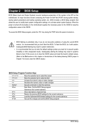
.... BIOS includes a BIOS Setup program that you not alter the default settings (unless you do it is turned off, the battery on the motherboard supplies the necessary power to the CMOS to activate certain system features. Inadequate BIOS flashing may result in Chapter 1 for how to clear the...user to modify basic system configuration settings or to keep the configuration values in the EFI on . • BIOS flashing is turned on the motherboard. Its major functions include conducting the Power-On Self-Test (POST) during the POST when the power is potentially risky, if you need to...
.... BIOS includes a BIOS Setup program that you not alter the default settings (unless you do it is turned off, the battery on the motherboard supplies the necessary power to the CMOS to activate certain system features. Inadequate BIOS flashing may result in Chapter 1 for how to clear the...user to modify basic system configuration settings or to keep the configuration values in the EFI on . • BIOS flashing is turned on the motherboard. Its major functions include conducting the Power-On Self-Test (POST) during the POST when the power is potentially risky, if you need to...
Manual
Page 130
...from the 2002/96/EC WEEE (Waste Electrical and Electronic Equipment) directive. Restriction of Hazardous Substances (RoHS) Directive Statement GIGABYTE products have been carefully selected to the waste collection centers for activation of the treatment, collection, recycling and disposal procedure. ...and ensure that do not use of life" product. We believe that the information contained herein was accurate in all GIGABYTE motherboards fulfill European Union regulations for RoHS (Restriction of Certain Hazardous Substances in Electrical and Electronic Equipment) and WEEE (Waste ...
...from the 2002/96/EC WEEE (Waste Electrical and Electronic Equipment) directive. Restriction of Hazardous Substances (RoHS) Directive Statement GIGABYTE products have been carefully selected to the waste collection centers for activation of the treatment, collection, recycling and disposal procedure. ...and ensure that do not use of life" product. We believe that the information contained herein was accurate in all GIGABYTE motherboards fulfill European Union regulations for RoHS (Restriction of Certain Hazardous Substances in Electrical and Electronic Equipment) and WEEE (Waste ...


