
User Manual
Page 1
All brand names and products are subject to change without notice. GIGABYTE ODIN Power Supply User's Manual ATX 12V version 2.2 power supply Products: ODIN GT / ODIN PRO Models: GE-S800A-D1, GE-S680A-D1, GE-S550A-D1 / GE-M800A-D1, GE-M680A-D1, GE-M550A-D1 Specifications are registered trademarks of their respective companies
All brand names and products are subject to change without notice. GIGABYTE ODIN Power Supply User's Manual ATX 12V version 2.2 power supply Products: ODIN GT / ODIN PRO Models: GE-S800A-D1, GE-S680A-D1, GE-S550A-D1 / GE-M800A-D1, GE-M680A-D1, GE-M550A-D1 Specifications are registered trademarks of their respective companies
User Manual
Page 2
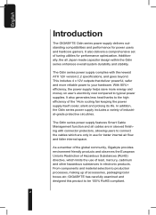
... addition, the Odin series power supply includes a variety of tuning utilities for performance optimization. The Odin series power supply complies with connector protectors, allowing users to your hardware. This includes 4 x 12V outputs that deliver powerful, safer and more energy and money on user's electricity cost compared to the high efficiency of accessories, packaging/color boxes etc; The Odin series power supply features Smart Cable Management function and...
... addition, the Odin series power supply includes a variety of tuning utilities for performance optimization. The Odin series power supply complies with connector protectors, allowing users to your hardware. This includes 4 x 12V outputs that deliver powerful, safer and more energy and money on user's electricity cost compared to the high efficiency of accessories, packaging/color boxes etc; The Odin series power supply features Smart Cable Management function and...

User Manual
Page 3
... Servicing to this power supply unit! Be sure to observe the instructions on installation in damage to the casing or computer-related devices. 9.Any loss/damage caused by the warranty: 1.Using the product incorrectly or in a manner other than the designed purpose. 2.Nonobservance of the proper operation provided. 3.Malfunction due to follow the installation process within the user manual...
... Servicing to this power supply unit! Be sure to observe the instructions on installation in damage to the casing or computer-related devices. 9.Any loss/damage caused by the warranty: 1.Using the product incorrectly or in a manner other than the designed purpose. 2.Nonobservance of the proper operation provided. 3.Malfunction due to follow the installation process within the user manual...
User Manual
Page 4
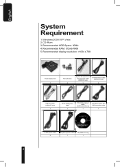
Recommended RAM: 512mb RAM 5. Windows 2000\ XP\ Vista 2. CD -Rom 3. Recommended HDD Space: 30Mb 4. English System Requirement 1. Recommended display resolution: >1024 x 768 Power Supply Unit 1 Fixing Screws 4 System fan speed control and power cable (ODIN GT only) 1 Thermal sensor cable (ODIN GT only) 4 USB Converter (ODIN GT only) 1 PCI-E (Red) power cable 1 PCI-E (Blue) power cable (800W & 680W only) 1 Peripheral power with FDD connector cable 1 S-ATA power cable 2 Peripheral power cable 1 CD (ODIN GT only) 1 4
Recommended RAM: 512mb RAM 5. Windows 2000\ XP\ Vista 2. CD -Rom 3. Recommended HDD Space: 30Mb 4. English System Requirement 1. Recommended display resolution: >1024 x 768 Power Supply Unit 1 Fixing Screws 4 System fan speed control and power cable (ODIN GT only) 1 Thermal sensor cable (ODIN GT only) 4 USB Converter (ODIN GT only) 1 PCI-E (Red) power cable 1 PCI-E (Blue) power cable (800W & 680W only) 1 Peripheral power with FDD connector cable 1 S-ATA power cable 2 Peripheral power cable 1 CD (ODIN GT only) 1 4
User Manual
Page 6
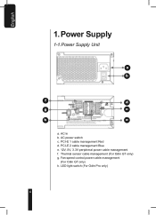
LED light switch (For Odin Pro only) 6 Fan speed control power cable management (For Odin GT only) h. English 1. PCI-E 1 cable management Red d. PCI-E 2 cable management Blue e. 12V, 5V, 3.3V peripheral power cable management f. Thermal sensor cable management (For Odin GT only) g. AC In b. Power Supply 1-1.Power Supply Unit a b f d g c h e a. AC power switch c.
LED light switch (For Odin Pro only) 6 Fan speed control power cable management (For Odin GT only) h. English 1. PCI-E 1 cable management Red d. PCI-E 2 cable management Blue e. 12V, 5V, 3.3V peripheral power cable management f. Thermal sensor cable management (For Odin GT only) g. AC In b. Power Supply 1-1.Power Supply Unit a b f d g c h e a. AC power switch c.

User Manual
Page 7
... power with FDD connector cable i. USB Converter (For Odin GT only) 7 Smart cable management Peripheral power cable h. Smart cable management S-ATA power cable j. Smart cable management System fan speed control and power cable (For Odin GT only) l. Smart cable management - USB Data connector (For Odin GT only) f. Smart cable management PCI-E (Red and Blue) power cable g. Smart cable management Thermal sensor cable (For Odin GT only) k. English 1-2.Power Supply Cables a. 24-pin main power connector b. 8-pin +12V CPU power connector c. 4-pin +12V CPU power connector d. 6-pin PCI-E power...
... power with FDD connector cable i. USB Converter (For Odin GT only) 7 Smart cable management Peripheral power cable h. Smart cable management S-ATA power cable j. Smart cable management System fan speed control and power cable (For Odin GT only) l. Smart cable management - USB Data connector (For Odin GT only) f. Smart cable management PCI-E (Red and Blue) power cable g. Smart cable management Thermal sensor cable (For Odin GT only) k. English 1-2.Power Supply Cables a. 24-pin main power connector b. 8-pin +12V CPU power connector c. 4-pin +12V CPU power connector d. 6-pin PCI-E power...
User Manual
Page 8
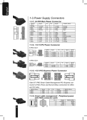
...1-3.Power Supply Connectors 1-3-1. 24-PIN Main Power Connector 18AWG (Wire) Orange Blue Black Green (22AWG) Black Black Black Red Red Red Black Signal +3.3Vdc -12Vdc COM PS-ON COM COM COM +5Vdc +5Vdc +5Vdc COM Pin Pin ...PIN 12V+ 18AWG Signal Pin Pin Signal 18AWG (Wire) (Wire) Yellow +12V2DC 3 1 COM Black Yellow +12V2DC 4 2 COM Black 1-3-3. +12 V PCI Express Power Connector Odin GT, PRO Smart Cable Management PCI-Express con- nector to PSU (There are Red and Blue connectors for differ- Smart cable management - Peripheral power with FDD connector cable Pin Signal 18AWG (Wire...
...1-3.Power Supply Connectors 1-3-1. 24-PIN Main Power Connector 18AWG (Wire) Orange Blue Black Green (22AWG) Black Black Black Red Red Red Black Signal +3.3Vdc -12Vdc COM PS-ON COM COM COM +5Vdc +5Vdc +5Vdc COM Pin Pin ...PIN 12V+ 18AWG Signal Pin Pin Signal 18AWG (Wire) (Wire) Yellow +12V2DC 3 1 COM Black Yellow +12V2DC 4 2 COM Black 1-3-3. +12 V PCI Express Power Connector Odin GT, PRO Smart Cable Management PCI-Express con- nector to PSU (There are Red and Blue connectors for differ- Smart cable management - Peripheral power with FDD connector cable Pin Signal 18AWG (Wire...

User Manual
Page 9
... to connect the rear I/O. Peripheral power with motherboard's users' manual. 9 Pin Signal 1 2 Data - 3 Data + 4 Ground 5 20AWG (Wire) White Green Black Incorrect connector installation may possible burn out the motherboard and other components. USB Data Connector For ODIN GT series power supply only, please refer to the motherboard's user manual for connecting the USB data connector to motherboard's USB port or using the USB converter to observe the instructions on installation in the manual. Peripheral power with SATA HDD connector cable Pin Signal...
... to connect the rear I/O. Peripheral power with motherboard's users' manual. 9 Pin Signal 1 2 Data - 3 Data + 4 Ground 5 20AWG (Wire) White Green Black Incorrect connector installation may possible burn out the motherboard and other components. USB Data Connector For ODIN GT series power supply only, please refer to the motherboard's user manual for connecting the USB data connector to motherboard's USB port or using the USB converter to observe the instructions on installation in the manual. Peripheral power with SATA HDD connector cable Pin Signal...
User Manual
Page 10
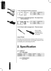
Fan Speed Control connectors Pin Signal 1 Com 2 +5VDC 3 Signal 24 AWG (Wire) Black Red Yellow 1-3-10.Smart Cable Management - Specification 2-1 INPUT 2-1-1 VOLTAGE Model Name GE-S800A-D1 GE-S680A-D1 GE-S550A-D1 Minimum 90 90 90 Nominal ...cause the CPU overheating, and could damage the CPU. 2. Fan Speed Control connectors Pin Signal 24 AWG (Wire) 1 Com Black 2 +5VDC Red 3 Signal Yellow 1-3-11.Smart cable management - English 1-3-9. Thermal sensor Smart cable management Thermal sensor Connector CAUTION Don't place the Thermal sensor between CPU and Cooler;...
Fan Speed Control connectors Pin Signal 1 Com 2 +5VDC 3 Signal 24 AWG (Wire) Black Red Yellow 1-3-10.Smart Cable Management - Specification 2-1 INPUT 2-1-1 VOLTAGE Model Name GE-S800A-D1 GE-S680A-D1 GE-S550A-D1 Minimum 90 90 90 Nominal ...cause the CPU overheating, and could damage the CPU. 2. Fan Speed Control connectors Pin Signal 24 AWG (Wire) 1 Com Black 2 +5VDC Red 3 Signal Yellow 1-3-11.Smart cable management - English 1-3-9. Thermal sensor Smart cable management Thermal sensor Connector CAUTION Don't place the Thermal sensor between CPU and Cooler;...

User Manual
Page 11
... full load (typical) and 115Vac and 230Vac input (For 20%, 50%, 100% load condition) 2-1-6 LEAKAGE CURRENT 3.5mA max. 2-1-7 POWER FACTOR PF> 0.9 Voltage Max Load *1 Min Load Peak Load Regula tion Ripple & Noise 11 2-2 OUTPUT +5V 28.0 A 2.0 A -- +5, -4% 50 mV +3.3V 30.0 A 0.5 A -- +5, -3% 50 mV +12V1 18.0 A 1.0 A -- +5, -4% 120 mV +12V2 18.0 A...last up to 12 seconds with no more than one occurrence per minute. - GE-M680A-D1)/ 550W (GE-S550A-D1; The Combined power of +5V +3.3V is 800W MAX (GE-S800A-D1; GE-M550A-D1) English 2-1-3 CURRENT 115Vac - 8.0A max / 230Vax - 4.0A max 115Vac - 10....
... full load (typical) and 115Vac and 230Vac input (For 20%, 50%, 100% load condition) 2-1-6 LEAKAGE CURRENT 3.5mA max. 2-1-7 POWER FACTOR PF> 0.9 Voltage Max Load *1 Min Load Peak Load Regula tion Ripple & Noise 11 2-2 OUTPUT +5V 28.0 A 2.0 A -- +5, -4% 50 mV +3.3V 30.0 A 0.5 A -- +5, -3% 50 mV +12V1 18.0 A 1.0 A -- +5, -4% 120 mV +12V2 18.0 A...last up to 12 seconds with no more than one occurrence per minute. - GE-M680A-D1)/ 550W (GE-S550A-D1; The Combined power of +5V +3.3V is 800W MAX (GE-S800A-D1; GE-M550A-D1) English 2-1-3 CURRENT 115Vac - 8.0A max / 230Vax - 4.0A max 115Vac - 10....

User Manual
Page 12
English 2-3 REMOTE ON/OFF TTL High/PS-OFF; The DC output voltage will stay within the rating. TTL Low/PS-ON VIL = 0.8V max, IIL = -1.6mAmax@Vin=0.4V VIH = 2.0V min @ Iin=-200uA, VIH = 5.25Vmax@open ... capacitive load as below: +3.3V 1000uF +12V1 2200uF +12V2 2200uF +12V3 2200uF +12V4 2200uF -12V NA +5Vsb 1uF 2-9 RISE TIME 20ms max at 230Vac input 2-5 POWER GOOD DELAY 100-500 msec 2-6 POWER FAIL DELAY >1msec. 2-7 TURN-ON DELAY TIME 2000 msec max. G. 12
English 2-3 REMOTE ON/OFF TTL High/PS-OFF; The DC output voltage will stay within the rating. TTL Low/PS-ON VIL = 0.8V max, IIL = -1.6mAmax@Vin=0.4V VIH = 2.0V min @ Iin=-200uA, VIH = 5.25Vmax@open ... capacitive load as below: +3.3V 1000uF +12V1 2200uF +12V2 2200uF +12V3 2200uF +12V4 2200uF -12V NA +5Vsb 1uF 2-9 RISE TIME 20ms max at 230Vac input 2-5 POWER GOOD DELAY 100-500 msec 2-6 POWER FAIL DELAY >1msec. 2-7 TURN-ON DELAY TIME 2000 msec max. G. 12

User Manual
Page 13
... OTP, or short protection is triggered, the main output will be reset by cycling the DC remote on/off . GE-M800A-D1; The main outputs can trip and shutdown the power supply at 100°C. GE-M680A-D1) +12V3, +12V4 output 38A max (GE-S800A-D1; GE-S680A-D1;...2-10-1.OVER CURRENT PROTECTION No exceeding 240VA every output voltage (Beside of internal current overloading or a cooling fan failure. 2-11 ENVIRONMENT 2-11-1 Operating Temp 13 GE-M800A-D1; temperature sensor, which can be latched off or AC power +5Vsb output is automatically recovered when a fault condition is ...
... OTP, or short protection is triggered, the main output will be reset by cycling the DC remote on/off . GE-M800A-D1; The main outputs can trip and shutdown the power supply at 100°C. GE-M680A-D1) +12V3, +12V4 output 38A max (GE-S800A-D1; GE-S680A-D1;...2-10-1.OVER CURRENT PROTECTION No exceeding 240VA every output voltage (Beside of internal current overloading or a cooling fan failure. 2-11 ENVIRONMENT 2-11-1 Operating Temp 13 GE-M800A-D1; temperature sensor, which can be latched off or AC power +5Vsb output is automatically recovered when a fault condition is ...

User Manual
Page 15
... cards (SLI, crossfire or quad - SLI), please use the PCI-E connector from the power supply to open your old power supply. 3. English 3. Installation Instruction (For a new system, please go directly to your PCI express graphic card's user manual for PCI-E power, please use Smart Cable management PCI-E power connectors. Remove the existing power supply from your computer case. 4. Connect the 4 / 8-pin 12V CPU power connector to your computer case 6. When there is...
... cards (SLI, crossfire or quad - SLI), please use the PCI-E connector from the power supply to open your old power supply. 3. English 3. Installation Instruction (For a new system, please go directly to your PCI express graphic card's user manual for PCI-E power, please use Smart Cable management PCI-E power connectors. Remove the existing power supply from your computer case. 4. Connect the 4 / 8-pin 12V CPU power connector to your computer case 6. When there is...

User Manual
Page 16
... series only) 16 This allows Odin GT power supply to the CPU fan 12. It can be used in high temperature environment. Connect Smart Cable Management - Thermal Sensor cable, use Smart Cable Management power connectors. 11. The thermal tape has an insulating property. With a Smart Cable Management -Fan speed control power connector, users may connect two 3-pin system fans. To connect peripheral devices, please use the thermal tape to stick the thermal...
... series only) 16 This allows Odin GT power supply to the CPU fan 12. It can be used in high temperature environment. Connect Smart Cable Management - Thermal Sensor cable, use Smart Cable Management power connectors. 11. The thermal tape has an insulating property. With a Smart Cable Management -Fan speed control power connector, users may connect two 3-pin system fans. To connect peripheral devices, please use the thermal tape to stick the thermal...
User Manual
Page 17
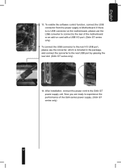
... I/O USB port, please use the converter, which is no USB connector on the motherboard, please use the USB converter to connect to the rear USB port by passing the rear slot. (Odin GT series only) 14. After installation, connect the power cord to Motherboard. To enable the software control function, connect the USB connector from the power supply to the Odin GT power supply unit. English 13. If...
... I/O USB port, please use the converter, which is no USB connector on the motherboard, please use the USB converter to connect to the rear USB port by passing the rear slot. (Odin GT series only) 14. After installation, connect the power cord to Motherboard. To enable the software control function, connect the USB connector from the power supply to the Odin GT power supply unit. English 13. If...
User Manual
Page 18
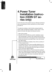
...driver needed for automatic start , please open the ODD folder and double click on the desktop or in the menu for Odin GT. Copy the link into the system step by double clicking on the "Power Tuner" logo on the setup.exe file to install manually. 3. Start up by step. 4. Follow the instruction and install Power... shown as left. (It's possible that a new hardware is found, and there is not a problem; To enable the software control function, please install the power supply management software, "Power Turner", in this manual. We continually refine and improve our products to ...
...driver needed for automatic start , please open the ODD folder and double click on the desktop or in the menu for Odin GT. Copy the link into the system step by double clicking on the "Power Tuner" logo on the setup.exe file to install manually. 3. Start up by step. 4. Follow the instruction and install Power... shown as left. (It's possible that a new hardware is found, and there is not a problem; To enable the software control function, please install the power supply management software, "Power Turner", in this manual. We continually refine and improve our products to ...

User Manual
Page 19
... menu Power Supply Light switch *1 When the button or fan flashes in red, there is clicked, there will be controlled by a click of Current in a window 19 Power Tuner main page The images below display the Power Tuner window; Please check if the system is still in proper condition. *2 When the "all " for single window *2 PSU fan speed...
... menu Power Supply Light switch *1 When the button or fan flashes in red, there is clicked, there will be controlled by a click of Current in a window 19 Power Tuner main page The images below display the Power Tuner window; Please check if the system is still in proper condition. *2 When the "all " for single window *2 PSU fan speed...

User Manual
Page 20
... the sensor to which the PSU use mouse to provide users with a silent power supply; Normal mode: A balance setting between °C & °F Confirm setting Cancel setting Performance mode: High Fan speed to cool down the power supply and system at higher fan speed will automatically rise to keep the system silent; P-Tuner Voltage page Power Supply fan / System fan switch Fan curve Start Voltage Start Temperature...
... the sensor to which the PSU use mouse to provide users with a silent power supply; Normal mode: A balance setting between °C & °F Confirm setting Cancel setting Performance mode: High Fan speed to cool down the power supply and system at higher fan speed will automatically rise to keep the system silent; P-Tuner Voltage page Power Supply fan / System fan switch Fan curve Start Voltage Start Temperature...

User Manual
Page 21
P-Tuner Alarm: Voltage 21 It is safe to adjust the voltage within Intel spec. It may cause the system into protection mode. (Power Tuner only allows the power supply to adjust the voltage setting.) 8. P-Tuner Alarm: Watt 9. English Please don't set the voltage over Intel spec.
P-Tuner Alarm: Voltage 21 It is safe to adjust the voltage within Intel spec. It may cause the system into protection mode. (Power Tuner only allows the power supply to adjust the voltage setting.) 8. P-Tuner Alarm: Watt 9. English Please don't set the voltage over Intel spec.
User Manual
Page 23
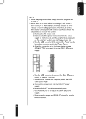
... below , or use ODIN GT PSU jump start kit to the hardware, normally caused by overvoltage or under-voltage protection. Disconnect all the power connectors from the power supply to another computer. Use the USB converter kit to connect the Power supply to motherboard, and the peripheral devices such as in the computer, which the USB cable connects to re-adjust the ODIN GT power supply. Install Power Tuner in...
... below , or use ODIN GT PSU jump start kit to the hardware, normally caused by overvoltage or under-voltage protection. Disconnect all the power connectors from the power supply to another computer. Use the USB converter kit to connect the Power supply to motherboard, and the peripheral devices such as in the computer, which the USB cable connects to re-adjust the ODIN GT power supply. Install Power Tuner in...

