

Manual
Page 1
... System Cover R120-P30 Quick Reference Guide Removing Fan Duct P/N:25ME0-R12000-Q0R Installing Memory Installing Hard Disk Drive Installing PCI Expansion Card Front Panel LED and Buttons System Front and Rear View System Front View System Rear View 1 HDD bays 2 Front USB 2.0 ports 3 Front panel LED and buttons 4 ID switch button 5 Power switch button 1 Power supply module cord socket 2 ID switch button 3 Power swith button 4 LAN ports 5 10G LAN ports 6 VGA port 7 Serial port 8 10/100 Server management LAN port 9 USB 2.0 ports 10 System status LED 11 Low-profile riser card bay
... System Cover R120-P30 Quick Reference Guide Removing Fan Duct P/N:25ME0-R12000-Q0R Installing Memory Installing Hard Disk Drive Installing PCI Expansion Card Front Panel LED and Buttons System Front and Rear View System Front View System Rear View 1 HDD bays 2 Front USB 2.0 ports 3 Front panel LED and buttons 4 ID switch button 5 Power switch button 1 Power supply module cord socket 2 ID switch button 3 Power swith button 4 LAN ports 5 10G LAN ports 6 VGA port 7 Serial port 8 10/100 Server management LAN port 9 USB 2.0 ports 10 System status LED 11 Low-profile riser card bay
Manual
Page 2
... reserved. Changes to their respective owners. The trademarks mentioned in this manual is protected by copyright laws and is the property of GIGABYTE. Copyright © 2015 GIGA-BYTE TECHNOLOGY CO., LTD. No part of this manual may be reproduced, copied, translated, transmitted, or published in the use of this product, GIGABYTE provides the following types of sales, marketing & technical materials...
... reserved. Changes to their respective owners. The trademarks mentioned in this manual is protected by copyright laws and is the property of GIGABYTE. Copyright © 2015 GIGA-BYTE TECHNOLOGY CO., LTD. No part of this manual may be reproduced, copied, translated, transmitted, or published in the use of this product, GIGABYTE provides the following types of sales, marketing & technical materials...
Manual
Page 3
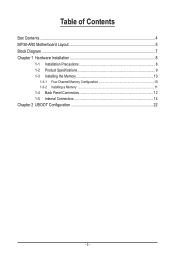
Table of Contents Box Contents...4 MP30-AR0 Motherboard Layout 5 Block Diagram...7 Chapter 1 Hardware Installation 8 1-1 Installation Precautions 8 1-2 Product Specifications 9 1-3 Installing the Memory 10 1-3-1 Four Channel Memory Configuration 10 1-3-2 Installing a Memory 11 1-4 Back Panel Connectors 12 1-5 Internal Connectors 14 Chapter 2 UBOOT Configuration 22 - 3 -
Table of Contents Box Contents...4 MP30-AR0 Motherboard Layout 5 Block Diagram...7 Chapter 1 Hardware Installation 8 1-1 Installation Precautions 8 1-2 Product Specifications 9 1-3 Installing the Memory 10 1-3-1 Four Channel Memory Configuration 10 1-3-2 Installing a Memory 11 1-4 Back Panel Connectors 12 1-5 Internal Connectors 14 Chapter 2 UBOOT Configuration 22 - 3 -
Manual
Page 4
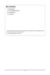
Box Contents Motherboard Four SATA 6Gb/s cables User's Manual I/O Shield • The box contents above are subject to change without notice. • The motherboard image is for reference only and the actual items shall depend on the product package you obtain. The box contents are for reference only. - 4 -
Box Contents Motherboard Four SATA 6Gb/s cables User's Manual I/O Shield • The box contents above are subject to change without notice. • The motherboard image is for reference only and the actual items shall depend on the product package you obtain. The box contents are for reference only. - 4 -

Manual
Page 6
... closed and set to 2-3 pins (Default setting), in order to Page 22 for Server system) System fan connector#2 PMBus header Clear CMOS jumper System fan connector#3 HDD back plane board header Case open intrusion alert header IPMB connector System fan connector#4 SATA port 3 DOM support jumper SATA3 6Gb/s connectors PCI Express x16 slot Battery socket PCI Express x16 slot BMC firmware readiness LED Channel 3 slot 0 Channel 3 slot 1 Channel 4 slot 0 Channel 4 slot 1 CAUTION! Please refer to reduce any risk of hard disk damage. Item Code 1 LED_STA 2 USB2_MLAN...
... closed and set to 2-3 pins (Default setting), in order to Page 22 for Server system) System fan connector#2 PMBus header Clear CMOS jumper System fan connector#3 HDD back plane board header Case open intrusion alert header IPMB connector System fan connector#4 SATA port 3 DOM support jumper SATA3 6Gb/s connectors PCI Express x16 slot Battery socket PCI Express x16 slot BMC firmware readiness LED Channel 3 slot 0 Channel 3 slot 1 Channel 4 slot 0 Channel 4 slot 1 CAUTION! Please refer to reduce any risk of hard disk damage. Item Code 1 LED_STA 2 USB2_MLAN...
Manual
Page 8
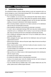
... shielding container. • Before unplugging the power supply cable from the power outlet before installing or removing the motherboard or other hardware components. • When connecting hardware components to the internal connectors on the motherboard, make sure the power supply voltage has been set according to the local voltage standard. • Before using the product, please verify that all cables and power connectors of your hardware components are connected. • To prevent damage to...
... shielding container. • Before unplugging the power supply cable from the power outlet before installing or removing the motherboard or other hardware components. • When connecting hardware components to the internal connectors on the motherboard, make sure the power supply voltage has been set according to the local voltage standard. • Before using the product, please verify that all cables and power connectors of your hardware components are connected. • To prevent damage to...
Manual
Page 9
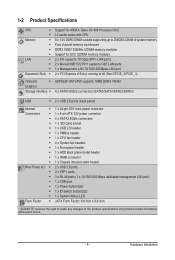
...; 1 x CPU fan header ŠŠ 4 x System fan headers ŠŠ 1 x Front panel header ŠŠ 1 x HDD Back plane borad header ŠŠ 1 x IPMB connector ŠŠ 1 x Chassis intrusion alert header ŠŠ 2 x USB 2.0 ports ŠŠ 2 x SFP+ ports ŠŠ 3 x RJ-45 ports (1 x 10/100/1000 Mbps dedicated management LAN port) ŠŠ 1 x COM port ŠŠ 1 x Power button/LED ŠŠ 1 x ID Switch button/LED ŠŠ 1 x System Status LED Š...
...; 1 x CPU fan header ŠŠ 4 x System fan headers ŠŠ 1 x Front panel header ŠŠ 1 x HDD Back plane borad header ŠŠ 1 x IPMB connector ŠŠ 1 x Chassis intrusion alert header ŠŠ 2 x USB 2.0 ports ŠŠ 2 x SFP+ ports ŠŠ 3 x RJ-45 ports (1 x 10/100/1000 Mbps dedicated management LAN port) ŠŠ 1 x COM port ŠŠ 1 x Power button/LED ŠŠ 1 x ID Switch button/LED ŠŠ 1 x System Status LED Š...
Manual
Page 10
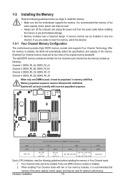
... detect the specifications and capacity of the original memory bandwidth. Four Channel mode cannot be used . • Always turn off the computer and unplug the power cord from the power outlet before installing the memory to insert the memory, switch the direction. When enabling Four Channel mode with two or four memory modules, it must be followed with incorrect populated sequence. The eight DDR3 memory sockets are unable...
... detect the specifications and capacity of the original memory bandwidth. Four Channel mode cannot be used . • Always turn off the computer and unplug the power cord from the power outlet before installing the memory to insert the memory, switch the direction. When enabling Four Channel mode with two or four memory modules, it must be followed with incorrect populated sequence. The eight DDR3 memory sockets are unable...

Manual
Page 11
... to the memory module. Hardware Installation 1-3-2 Installing a Memory Before installing a memory module, make sure to turn off the computer and unplug the power cord from the power outlet to prevent damage to remove the DIMM module. 1 2 2 - 11 - Insert the DIMM memory module vertically into the DIMM slot, and push it down. Note: For dual-channel operation, DIMMs must be installed in matched pairs. Step 2. Step 3. Installation Step: Step 1. Be sure to lock the DIMM module. Close...
... to the memory module. Hardware Installation 1-3-2 Installing a Memory Before installing a memory module, make sure to turn off the computer and unplug the power cord from the power outlet to prevent damage to remove the DIMM module. 1 2 2 - 11 - Insert the DIMM memory module vertically into the DIMM slot, and push it down. Note: For dual-channel operation, DIMMs must be installed in matched pairs. Step 2. Step 3. Installation Step: Step 1. Be sure to lock the DIMM module. Close...
Manual
Page 12
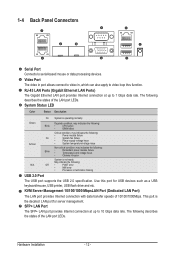
...• NMI error • Processor or terminator missing USB 2.0 Port The USB port supports the USB 2.0 specification. 1-4 Back Panel Connectors Serial Port Connects to video loop thru function. KVM Server Management 10/100/1000 MbpsLAN Port (Dedicated LAN Port) The LAN port provides Internet connection with data transfer speeds of the LAN port LEDs. Video Port The video in port allows connect to video in, which can also apply to serial-based mouse or data processing devices. The following : Blink • • Redundant power module failure Temperature and voltage issue...
...• NMI error • Processor or terminator missing USB 2.0 Port The USB port supports the USB 2.0 specification. 1-4 Back Panel Connectors Serial Port Connects to video loop thru function. KVM Server Management 10/100/1000 MbpsLAN Port (Dedicated LAN Port) The LAN port provides Internet connection with data transfer speeds of the LAN port LEDs. Video Port The video in port allows connect to video in, which can also apply to serial-based mouse or data processing devices. The following : Blink • • Redundant power module failure Temperature and voltage issue...
Manual
Page 13
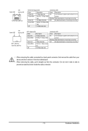
... Yellow Blink rate 1 Gbps data rate Identify 1 Gbps data rate Off 100 Mbps data rate Link/Activity LED: State Description On Link between system and network or no access Blinking Data transmission or receiving is occurring Off No data transmission or receiving is occurring • When removing the cable connected to a back panel connector, first remove the cable from your device and then remove it from the motherboard. • When removing the cable, pull...
... Yellow Blink rate 1 Gbps data rate Identify 1 Gbps data rate Off 100 Mbps data rate Link/Activity LED: State Description On Link between system and network or no access Blinking Data transmission or receiving is occurring Off No data transmission or receiving is occurring • When removing the cable connected to a back panel connector, first remove the cable from your device and then remove it from the motherboard. • When removing the cable, pull...

Manual
Page 14
... Fan) 8) SYS_FAN4 (System Fan) 9) SATA2/3/0/1 11 5 1 10) IPMB 11) FP_1 12) BP_1 13) CASE_OPE 14) LED_BMC 15) BAT1 16) SATA_DOM0 17) CLR_CMOS Read the following guidelines before turning on the computer, make sure your devices are compliant with the connectors you wish to connect. • Before installing the devices, be sure to the connector on the motherboard. Unplug the power cord...
... Fan) 8) SYS_FAN4 (System Fan) 9) SATA2/3/0/1 11 5 1 10) IPMB 11) FP_1 12) BP_1 13) CASE_OPE 14) LED_BMC 15) BAT1 16) SATA_DOM0 17) CLR_CMOS Read the following guidelines before turning on the computer, make sure your devices are compliant with the connectors you wish to connect. • Before installing the devices, be sure to the connector on the motherboard. Unplug the power cord...
Manual
Page 15
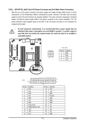
... to the CPU. The power connector possesses a foolproof design. Before connecting the power connector, first make sure the power supply is recommended that a power supply that does not provide the required power, the result can withstand high power consumption be used (500W or greater). If the 12V power connector is not connected, the computer will not start. • To meet expansion requirements, it is turned off and all the components on the motherboard.
... to the CPU. The power connector possesses a foolproof design. Before connecting the power connector, first make sure the power supply is recommended that a power supply that does not provide the required power, the result can withstand high power consumption be used (500W or greater). If the 12V power connector is not connected, the computer will not start. • To meet expansion requirements, it is turned off and all the components on the motherboard.
Manual
Page 16
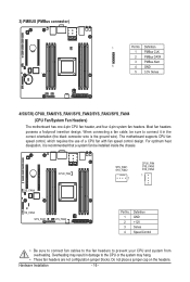
... the headers. The motherboard supports CPU fan speed control, which requires the use of a CPU fan with fan speed control design. 3) PMBUS (PMBus connector) 1 Pin No. When connecting a fan cable, be sure to connect it is the ground wire). SYS_FAN4 CPU0_FAN SYS_FAN1 SYS_FAN2 1 CPU0_FAN SYS_FAN3 SYS_FAN4 1 SYS_FAN3 SYS_FAN1 SYS_FAN2 Pin No. 1 2 3 4 Definition GND +12V Sense Speed Control • Be sure to connect fan cables to the fan headers to the CPU or the system may...
... the headers. The motherboard supports CPU fan speed control, which requires the use of a CPU fan with fan speed control design. 3) PMBUS (PMBus connector) 1 Pin No. When connecting a fan cable, be sure to connect it is the ground wire). SYS_FAN4 CPU0_FAN SYS_FAN1 SYS_FAN2 1 CPU0_FAN SYS_FAN3 SYS_FAN4 1 SYS_FAN3 SYS_FAN1 SYS_FAN2 Pin No. 1 2 3 4 Definition GND +12V Sense Speed Control • Be sure to connect fan cables to the fan headers to the CPU or the system may...

Manual
Page 17
Hardware Installation Definition 1 Clock 2 GND 3 3 Data - 17 - If more than two hard drives are configured, the total number of hard drives must be an even number. • A RAID 10 configuration requires four hard drives. (Note) When a RAID configuration is built across the SATA 6Gb/s channels, the system performance of the RAID configuration may vary depends on the devices are compatible with SATA 3Gb/s and 1.5Gb/s standard. Please see page 22 for SATA DOM jumper setting. 7 SATA2...
Hardware Installation Definition 1 Clock 2 GND 3 3 Data - 17 - If more than two hard drives are configured, the total number of hard drives must be an even number. • A RAID 10 configuration requires four hard drives. (Note) When a RAID configuration is built across the SATA 6Gb/s channels, the system performance of the RAID configuration may vary depends on the devices are compatible with SATA 3Gb/s and 1.5Gb/s standard. Please see page 22 for SATA DOM jumper setting. 7 SATA2...
Manual
Page 18
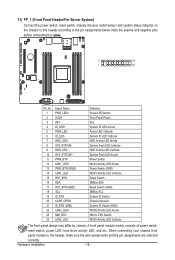
... power switch, reset switch, power LED, hard drive activity LED, and etc. When connecting your chassis front panel module to this header according to the pin assignments below. ID_LED- Hardware Installation - 18 - SYS_STATUS+ PWR_BTN LAN1_LED+ PWR_BTN (GND) LAN1_LED- Definition Power LED Anode Front Panel Power Key System ID LED Anode Power LED Cathode System ID LED Cathode HDD Activity LED Anode System Fault LED Cathode HDD Activity LED Cathode System Fault LED Anode Power Switch NIC#1 Activity LED Anode Power Switch (GND) NIC#1 Activity LED Cathode Reset Switch SMBus SDA Reset...
... power switch, reset switch, power LED, hard drive activity LED, and etc. When connecting your chassis front panel module to this header according to the pin assignments below. ID_LED- Hardware Installation - 18 - SYS_STATUS+ PWR_BTN LAN1_LED+ PWR_BTN (GND) LAN1_LED- Definition Power LED Anode Front Panel Power Key System ID LED Anode Power LED Cathode System ID LED Cathode HDD Activity LED Anode System Fault LED Cathode HDD Activity LED Cathode System Fault LED Anode Power Switch NIC#1 Activity LED Anode Power Switch (GND) NIC#1 Activity LED Cathode Reset Switch SMBus SDA Reset...
Manual
Page 19
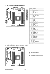
12) BP_1 (HDD Back Plane Board Hearders) 12 25 26 13) CASE_OPEN (Case open intrusion alert header) Pin No. 1 2 3 4 5 6 7 8 9 10 11 12 13 14 15 16 17 18 19 20 21 22 23 24 25 26 Definition BP_SGP_CLK NC BP_SGP_GLD FAN_GATE_N BP_SGP_DOUT GND KEY Reset GND BP_LED_A_N BP_LED_G_N GND BP_SGP_DIN NC GND SMB_BP_DATA GND SMB_BP_CLK P_3V3_AUX BMC_ACK P_3V3_AUX BMC_REQ GND KEY BP_PRESENSE GND Open: Normal operation. Closed: Active chassis intrustion alert. Hardware Installation - 19 -
12) BP_1 (HDD Back Plane Board Hearders) 12 25 26 13) CASE_OPEN (Case open intrusion alert header) Pin No. 1 2 3 4 5 6 7 8 9 10 11 12 13 14 15 16 17 18 19 20 21 22 23 24 25 26 Definition BP_SGP_CLK NC BP_SGP_GLD FAN_GATE_N BP_SGP_DOUT GND KEY Reset GND BP_LED_A_N BP_LED_G_N GND BP_SGP_DIN NC GND SMB_BP_DATA GND SMB_BP_CLK P_3V3_AUX BMC_ACK P_3V3_AUX BMC_REQ GND KEY BP_PRESENSE GND Open: Normal operation. Closed: Active chassis intrustion alert. Hardware Installation - 19 -
Manual
Page 20
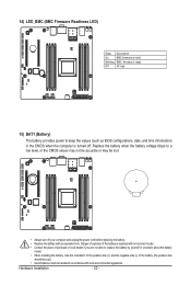
... the power cord before replacing the battery. • Replace the battery with an equivalent one. Danger of the battery (the positive side should face up). • Used batteries must be lost. • Always turn off . 14) LED_BMC (BMC Firmware Readiness LED) State Description On BMC firmware is initial Blinking BMC firmware is ready Off AC loss 15) BAT1 (Battery) The battery provides power to keep the values (such as BIOS configurations, date...
... the power cord before replacing the battery. • Replace the battery with an equivalent one. Danger of the battery (the positive side should face up). • Used batteries must be lost. • Always turn off . 14) LED_BMC (BMC Firmware Readiness LED) State Description On BMC firmware is initial Blinking BMC firmware is ready Off AC loss 15) BAT1 (Battery) The battery provides power to keep the values (such as BIOS configurations, date...

Manual
Page 21
... power cord from the jumper. Hardware Installation 16) SATA_DOM0 (SATA port 3 Jumper) CAUTION! • If the SATA DOM power is supplied by the motherboard, set the jumper to pin 1-2. • If the SATA DOM power is supplied by external power, set the jumper to pin 2-3. • If a SATA type hard drive is connected to the motherboard, please ensure the jumper is closed and set to 2-3 pins (Default setting), in the following. date information and BIOS configurations) and reset the CMOS values to remove the jumper...
... power cord from the jumper. Hardware Installation 16) SATA_DOM0 (SATA port 3 Jumper) CAUTION! • If the SATA DOM power is supplied by the motherboard, set the jumper to pin 1-2. • If the SATA DOM power is supplied by external power, set the jumper to pin 2-3. • If a SATA type hard drive is connected to the motherboard, please ensure the jumper is closed and set to 2-3 pins (Default setting), in the following. date information and BIOS configurations) and reset the CMOS values to remove the jumper...
Manual
Page 23
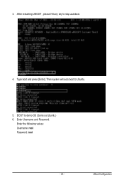
Then system will auto boot to stop autoboot. 4. After restarting UBOOT , please Hit any key to Ubuntu. 5. Type boot and press [Enter]. BOOT to demo OS (Same as Ubuntu ) 6. 3. UBoot Configuration Enter Username and Password. Enter the following values: Username: root Password: root - 23 -
Then system will auto boot to stop autoboot. 4. After restarting UBOOT , please Hit any key to Ubuntu. 5. Type boot and press [Enter]. BOOT to demo OS (Same as Ubuntu ) 6. 3. UBoot Configuration Enter Username and Password. Enter the following values: Username: root Password: root - 23 -
