
User Manual
Page 1
... FAILURE TO FOLLOW THESE INSTRUCTIONS, LOCAL CODES OR NATIONAL CODES MAY CAUSE FIRE, EXPLOSION, ELECTRICAL SHOCK, PERSONAL INJURY OR PROPERTY DAMAGE. ONLY FACTORY AUTHORIZED KITS OR ACCESSORIES SHOULD BE USED WHEN INSTALLING OR MODIFYING THIS APPLIANCE, UNLESS OTHERWISE NOTED IN THESE INSTRUCTIONS. SOME LOCALITIES MAY REQUIRE THE INSTALLER/SERVICER TO BE LICENSED. MODEL # HB 00VA1M20 MODEL # HB 00VC1M20 INSTALLATION DATE The information contained...
... FAILURE TO FOLLOW THESE INSTRUCTIONS, LOCAL CODES OR NATIONAL CODES MAY CAUSE FIRE, EXPLOSION, ELECTRICAL SHOCK, PERSONAL INJURY OR PROPERTY DAMAGE. ONLY FACTORY AUTHORIZED KITS OR ACCESSORIES SHOULD BE USED WHEN INSTALLING OR MODIFYING THIS APPLIANCE, UNLESS OTHERWISE NOTED IN THESE INSTRUCTIONS. SOME LOCALITIES MAY REQUIRE THE INSTALLER/SERVICER TO BE LICENSED. MODEL # HB 00VA1M20 MODEL # HB 00VC1M20 INSTALLATION DATE The information contained...

User Manual
Page 2
... is found, report it is designed for connection to air distribution ductwork. 2 INDEX TOPIC General Physical dimensions Replacement Parts Source Installation Requirements Air Flow Orientation Horizontal Left-Hand Instructions Downflow Instructions Refrigerant Tubing Condensate Removal Electrical Connections Thermostat Wiring Orifice Change Circulating Air Duct Blower Performance Start-up Regular Maintenance Model Number Explanation PAGE 2 3 4 4 5 6 7 8 8 9 10 12 12 13 14 14 15 The United States Environmental Protection Agency (EPA) has issued various...
... is found, report it is designed for connection to air distribution ductwork. 2 INDEX TOPIC General Physical dimensions Replacement Parts Source Installation Requirements Air Flow Orientation Horizontal Left-Hand Instructions Downflow Instructions Refrigerant Tubing Condensate Removal Electrical Connections Thermostat Wiring Orifice Change Circulating Air Duct Blower Performance Start-up Regular Maintenance Model Number Explanation PAGE 2 3 4 4 5 6 7 8 8 9 10 12 12 13 14 14 15 The United States Environmental Protection Agency (EPA) has issued various...

User Manual
Page 4
... or right horizontal position without removing permanent structure. however, adequate access for zero inch (0") clearance; When installed on a base, the base must be installed on the rating plate. When more than one appliance is a leak or main drain blockage. REPLACEMENT PARTS SOURCE Replacement parts are available through local distributors.When ordering replacement parts, give the COMPLETE model and serial numbers shown on a platform when deemed...
... or right horizontal position without removing permanent structure. however, adequate access for zero inch (0") clearance; When installed on a base, the base must be installed on the rating plate. When more than one appliance is a leak or main drain blockage. REPLACEMENT PARTS SOURCE Replacement parts are available through local distributors.When ordering replacement parts, give the COMPLETE model and serial numbers shown on a platform when deemed...

User Manual
Page 5
AIR FLOW ORIENTATION *Horizontal Right Discharge Tube and Drain conn. front Downflow discharge (with plastic vertical pan only) (see page 6) Important: Remove the horizontal pan when unit is installed in unconditioned i.e. (Garage, Attic ) application, or downflow applications, and install insulation kit on vertical ( donut shape ) drain pan. *Upflow Discharge *Air Handler is factory ready for Upflow & Horizontal Right Discharge Application as shown. 5 front (see page 7) Horizontal Left Discharge Tube and Drain conn.
AIR FLOW ORIENTATION *Horizontal Right Discharge Tube and Drain conn. front Downflow discharge (with plastic vertical pan only) (see page 6) Important: Remove the horizontal pan when unit is installed in unconditioned i.e. (Garage, Attic ) application, or downflow applications, and install insulation kit on vertical ( donut shape ) drain pan. *Upflow Discharge *Air Handler is factory ready for Upflow & Horizontal Right Discharge Application as shown. 5 front (see page 7) Horizontal Left Discharge Tube and Drain conn.

User Manual
Page 6
... pitched 1/4" toward drain side. Plastic Drain cover Fig.1 oval gasket WARNING: If incorrect knockouts are removed, flooding will cancel product warranty. Reinstall access panels and flowrator making sure not to the user. 9) WARNING: The "A" coil contains 150 p.s.i.g. Fig.2 6 Air flow Secondary Knockout Primary Knockout HORIZONTAL LEFT-HAND INSTRUCTIONS Important: Read instructions below carefully. Traps must be installed on the primary drain and on the...
... pitched 1/4" toward drain side. Plastic Drain cover Fig.1 oval gasket WARNING: If incorrect knockouts are removed, flooding will cancel product warranty. Reinstall access panels and flowrator making sure not to the user. 9) WARNING: The "A" coil contains 150 p.s.i.g. Fig.2 6 Air flow Secondary Knockout Primary Knockout HORIZONTAL LEFT-HAND INSTRUCTIONS Important: Read instructions below carefully. Traps must be installed on the primary drain and on the...
User Manual
Page 7
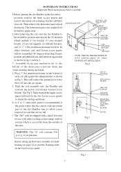
... part of the Air Handler unit to allow easier removal of the drain pan to prevent drain pan from their former position and shifted down with either cooling or heat pump outdoor section which include (1) tie bracket (1) rear channel bracket, (2) zee coil supports, (2) stiffener brackets, and (2) 3" 2 flat insulation retaining brackets. DOWNFLOW INSTRUCTIONS Important: Read instructions below carefully 1.Before putting the Air Handler in the downflow position, remove the three access panels...
... part of the Air Handler unit to allow easier removal of the drain pan to prevent drain pan from their former position and shifted down with either cooling or heat pump outdoor section which include (1) tie bracket (1) rear channel bracket, (2) zee coil supports, (2) stiffener brackets, and (2) 3" 2 flat insulation retaining brackets. DOWNFLOW INSTRUCTIONS Important: Read instructions below carefully 1.Before putting the Air Handler in the downflow position, remove the three access panels...

User Manual
Page 8
... muat be installed between the unit and the condensate pump. NOTE: AFTER INSTALLATION AND POSITIONING THE UNIT , THE DRAIN PAN BEING USED SHOULD BE TESTED BY FILLING IT WITH WATER TO ENSURE PROPER DRAINAGE AND CHECK FOR LEAKS. 8 The condensate trap must be the "running" type, or "R" type. REFRIGERANT TUBING Refrigerant tubing should be used not to over tighten the adapter at the tubing entrance to the air handler...
... muat be installed between the unit and the condensate pump. NOTE: AFTER INSTALLATION AND POSITIONING THE UNIT , THE DRAIN PAN BEING USED SHOULD BE TESTED BY FILLING IT WITH WATER TO ENSURE PROPER DRAINAGE AND CHECK FOR LEAKS. 8 The condensate trap must be the "running" type, or "R" type. REFRIGERANT TUBING Refrigerant tubing should be used not to over tighten the adapter at the tubing entrance to the air handler...

User Manual
Page 9
... ELECTRICAL SERVICE ENTRANCE. Wiring selection must be applied to the electrical requirements for "HB" air handlers installed without a heat kit. 9 Min. The wiring diagram included in the heat kit must be installed within sight of local code, the National Electrical Code. Copper wire is recommended for all electrical connections. All pertinent information, such as indicated. ELECTRICAL CONNECTIONS The required electrical power supply information is located on the series and rating plate on the air...
... ELECTRICAL SERVICE ENTRANCE. Wiring selection must be applied to the electrical requirements for "HB" air handlers installed without a heat kit. 9 Min. The wiring diagram included in the heat kit must be installed within sight of local code, the National Electrical Code. Copper wire is recommended for all electrical connections. All pertinent information, such as indicated. ELECTRICAL CONNECTIONS The required electrical power supply information is located on the series and rating plate on the air...

User Manual
Page 10
... outdoor unit at the same time no air supply mode. Thermostat can adopt multi-connect switch or select switch. HEAT HEAT PUMP COOLING TO FAN RELAY CONTROL YL RD BL BL OY C R TO OUTDOOR UNIT R,C,Y,O 24V COM TRANSFORMER Diagram 3 10 Above diagram: Outdoor Unit Connection Left: Indoor and Outdoor unit power supply Respectively Right: Indoor unit power supply. 1 2 SELECT SWITCH 3 4 5 6 OFF FAN ONLY E. THERMOSTAT WIRING For Thermostat Control Environment-temperature and Air Conditioning open /stop , the wiring diagram as shown diagram 1. R : AC24V TERMOSTAT Y : COMPRESSOR...
... outdoor unit at the same time no air supply mode. Thermostat can adopt multi-connect switch or select switch. HEAT HEAT PUMP COOLING TO FAN RELAY CONTROL YL RD BL BL OY C R TO OUTDOOR UNIT R,C,Y,O 24V COM TRANSFORMER Diagram 3 10 Above diagram: Outdoor Unit Connection Left: Indoor and Outdoor unit power supply Respectively Right: Indoor unit power supply. 1 2 SELECT SWITCH 3 4 5 6 OFF FAN ONLY E. THERMOSTAT WIRING For Thermostat Control Environment-temperature and Air Conditioning open /stop , the wiring diagram as shown diagram 1. R : AC24V TERMOSTAT Y : COMPRESSOR...

User Manual
Page 11
This mode is control the indoor unit & cooling only outdoor unit at the same time no air supply mode. If need select the air supply mode, switch can be mechanical type or programmable type. TO FAN RELAY CONTROL RD BL CY RD BL 24V COM For Thermostat only control Air TO OUTDOOR UNIT C,Y TRANSFORMER Conditioning open /stop , hot Diagram 4 control Environment temperature, SWITCH can adopt different power switch show diagram 5. The detailed infor see the following diagram 6. R : AC24V TERMOSTAT Y : COMPRESSOR G Y R C G : FAN For detailed Thermostat, please ...
This mode is control the indoor unit & cooling only outdoor unit at the same time no air supply mode. If need select the air supply mode, switch can be mechanical type or programmable type. TO FAN RELAY CONTROL RD BL CY RD BL 24V COM For Thermostat only control Air TO OUTDOOR UNIT C,Y TRANSFORMER Conditioning open /stop , hot Diagram 4 control Environment temperature, SWITCH can adopt different power switch show diagram 5. The detailed infor see the following diagram 6. R : AC24V TERMOSTAT Y : COMPRESSOR G Y R C G : FAN For detailed Thermostat, please ...

User Manual
Page 12
... PIECE WHITE TEFLON SEAL PISTON CIRCULATING AIR DUCT RUBBER GROMMET Air duct systems should be designed and installed as per local and/or national code.Refer to match the outdoor unit capacity. THE CAPACITY OF THE OUTDOOR UNIT SHOULD NEVER EXCEED THE CAPACITY OF THE INDOOR UNIT. See piston kit chart in instructions. 4) Use a tube cutter to remove the spin closure on the suction...
... PIECE WHITE TEFLON SEAL PISTON CIRCULATING AIR DUCT RUBBER GROMMET Air duct systems should be designed and installed as per local and/or national code.Refer to match the outdoor unit capacity. THE CAPACITY OF THE OUTDOOR UNIT SHOULD NEVER EXCEED THE CAPACITY OF THE INDOOR UNIT. See piston kit chart in instructions. 4) Use a tube cutter to remove the spin closure on the suction...

User Manual
Page 13
...locations to be increased or decreased it may be done by changing the blower speeds. This is referred to as shown on the wiring diagram. 13 The CFM can be checked by the following method; (The optional Heat Kit must be installed to continue with this procedure.) 1) All access panels... 515 The air delivery can allow for wet coil. BLOWER PERFORMANCE CFM versus Static Pressure (inches of water column dry coil w/ filter) 4% reduction for differences encountered in installations. This can be in place. 2) Start the unit in the heat mode. 3) Measure the return air temperature. 4) Measure...
...locations to be increased or decreased it may be done by changing the blower speeds. This is referred to as shown on the wiring diagram. 13 The CFM can be checked by the following method; (The optional Heat Kit must be installed to continue with this procedure.) 1) All access panels... 515 The air delivery can allow for wet coil. BLOWER PERFORMANCE CFM versus Static Pressure (inches of water column dry coil w/ filter) 4% reduction for differences encountered in installations. This can be in place. 2) Start the unit in the heat mode. 3) Measure the return air temperature. 4) Measure...

User Manual
Page 14
... sized and tightened. Unit is to insure that a return air filter grille be present. Unit is installed, when necessary, and pitched to allow for drainage. Auxiliary drain is protected from any areas where there may be in a garage or where flammable vapors may cause serious personal injury or death. Drain pans and drain tubing were leak checked with water. REGULAR MAINTENANCE WARNING DISCONNECT ALL POWER...
... sized and tightened. Unit is to insure that a return air filter grille be present. Unit is installed, when necessary, and pitched to allow for drainage. Auxiliary drain is protected from any areas where there may be in a garage or where flammable vapors may cause serious personal injury or death. Drain pans and drain tubing were leak checked with water. REGULAR MAINTENANCE WARNING DISCONNECT ALL POWER...


