
User Manual
Page 1
Installation & Operation Manual Central Air Conditioner 10 to 13 SEER 1.5 to 5 Tons Models: HC18-60A1VAR/S HC18-60C1VAR HC18-60D1VAR No.0010572324 K The information contained in this booklet is subject to change without notice.
Installation & Operation Manual Central Air Conditioner 10 to 13 SEER 1.5 to 5 Tons Models: HC18-60A1VAR/S HC18-60C1VAR HC18-60D1VAR No.0010572324 K The information contained in this booklet is subject to change without notice.

User Manual
Page 2
...'s warranty does not cover any damage or defect to the air conditioner caused by the manufacturer) into , onto, or in a fire or an electric shock due to dust, water, etc. If the service panel is the installer's responsibility to the imposition of refrigerants in accordance with National Codes and/or prevailing local codes and regulations. Failure to follow these instructions thoroughly before attempting installation...
...'s warranty does not cover any damage or defect to the air conditioner caused by the manufacturer) into , onto, or in a fire or an electric shock due to dust, water, etc. If the service panel is the installer's responsibility to the imposition of refrigerants in accordance with National Codes and/or prevailing local codes and regulations. Failure to follow these instructions thoroughly before attempting installation...

User Manual
Page 3
... (000) Btuh A SEER designation. H: Haier C System type - C=208/230-3-60, D=460-3-60, Y=575-3-60 A Body style R Compressor type Example: HC24A1VAR 1 A=10, B=11, C=12, D=13, E=14 1 Design series. 1 - 1st Generation V Electric: V=208/230-1-60; C: Air conditioner; General 5 6.2.Unit clearances 6 6.3.Refrigerant piping 6 6.4.Electrical wiring 10 7.System Startup 11 8.Operation 12 9.Miscellaneous 12 9.1.Replacement parts 12 9.2.Troubleshooting guide 12 9.3.Wiring diagram 12 1.INTRODUCTION This manual contains the installation and operating instructions for your new air conditioner.
... (000) Btuh A SEER designation. H: Haier C System type - C=208/230-3-60, D=460-3-60, Y=575-3-60 A Body style R Compressor type Example: HC24A1VAR 1 A=10, B=11, C=12, D=13, E=14 1 Design series. 1 - 1st Generation V Electric: V=208/230-1-60; C: Air conditioner; General 5 6.2.Unit clearances 6 6.3.Refrigerant piping 6 6.4.Electrical wiring 10 7.System Startup 11 8.Operation 12 9.Miscellaneous 12 9.1.Replacement parts 12 9.2.Troubleshooting guide 12 9.3.Wiring diagram 12 1.INTRODUCTION This manual contains the installation and operating instructions for your new air conditioner.

User Manual
Page 4
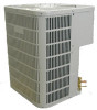
...[ 770 *770*805] [ 770 *770*905] Shipping Dimensions - Physical and electrical specifications are provided in Table 1 for the condensing unit are illustrated in Figure 1. In (mm) 3/8"[9.52] 3/8"[9....Amps 0.86 0.86 1.4 1.4 1.43 1.43 1.43 Fan Motor Rated HP 1/8 1/8 1/5 1/5 1/3 1/3 1/3 Nominal RPM 850 1000 1075 1075 1075 1075 1075 Liquid Line OD - Table 1: Model:HC18-60A1VAR/S 2 MODEL: HC18A1VAR HC24A1VAR HC30A1VAR HC36A1VAS HC42A1VAR HC48A1VAR HC60A1VAR Unit Supply Voltage 208/230-1-60 Normal Voltage Range Compressor Brand Minimum Circuit Amps 10.1 Max Fuse...
...[ 770 *770*805] [ 770 *770*905] Shipping Dimensions - Physical and electrical specifications are provided in Table 1 for the condensing unit are illustrated in Figure 1. In (mm) 3/8"[9.52] 3/8"[9....Amps 0.86 0.86 1.4 1.4 1.43 1.43 1.43 Fan Motor Rated HP 1/8 1/8 1/5 1/5 1/3 1/3 1/3 Nominal RPM 850 1000 1075 1075 1075 1075 1075 Liquid Line OD - Table 1: Model:HC18-60A1VAR/S 2 MODEL: HC18A1VAR HC24A1VAR HC30A1VAR HC36A1VAS HC42A1VAR HC48A1VAR HC60A1VAR Unit Supply Voltage 208/230-1-60 Normal Voltage Range Compressor Brand Minimum Circuit Amps 10.1 Max Fuse...

User Manual
Page 5
...Cooling Capacity Figure 1 Outdoor Unit With This Indoor Air handler Model Number Air Handler Compressor Cooling Capacity (Btu/h) SEER Rated HC18A1VAR HC24A1VAR HC30A1VAR HC36A1VAS HC42A1VAR HB2400VA1M20 HB2400VA1M20 HB3000VA1M20 HB3600VA1M20 HB4200VA1M25 brand Bristol Bristol Bristol Bristol Sanyo Sensible 13000 17000 20000 24000 28400 Total 18000 24000 28000 34000 40000 CFM(Outdoor...10 56000 10 2900 2900 The dimensions for 12 SEER systems respectively. Physical and electrical specifications are illustrated in Table 3 for the condensing unit are provided in Figure 1. In ...
...Cooling Capacity Figure 1 Outdoor Unit With This Indoor Air handler Model Number Air Handler Compressor Cooling Capacity (Btu/h) SEER Rated HC18A1VAR HC24A1VAR HC30A1VAR HC36A1VAS HC42A1VAR HB2400VA1M20 HB2400VA1M20 HB3000VA1M20 HB3600VA1M20 HB4200VA1M25 brand Bristol Bristol Bristol Bristol Sanyo Sensible 13000 17000 20000 24000 28400 Total 18000 24000 28000 34000 40000 CFM(Outdoor...10 56000 10 2900 2900 The dimensions for 12 SEER systems respectively. Physical and electrical specifications are illustrated in Table 3 for the condensing unit are provided in Figure 1. In ...

User Manual
Page 6
... 1.3 1.43 2.0 2.0 Fan Motor Rated HP 1/8 1/6 1/6 1/4 1/3 1/3 1/3 Nominal RPM 1000 840 840 850 1075 960 880 Liquid Line OD - Table 5: Model:HC18-60D1VAR MODEL: HC18D1VAR HC24D1VAR HC30D1VAR HC36D1VAR HC42D1VAR HC48D1VAR HC60D1VAR Unit Supply Voltage 208/230-1-60 Normal Voltage Range Compressor Brand 197 - 253 Bristol Minimum Circuit Amps 8.6 11.6 12.4 15.9 17.7 21.8 33.3 Max Fuse or Max CKT. Physical and electrical specifications are...
... 1.3 1.43 2.0 2.0 Fan Motor Rated HP 1/8 1/6 1/6 1/4 1/3 1/3 1/3 Nominal RPM 1000 840 840 850 1075 960 880 Liquid Line OD - Table 5: Model:HC18-60D1VAR MODEL: HC18D1VAR HC24D1VAR HC30D1VAR HC36D1VAR HC42D1VAR HC48D1VAR HC60D1VAR Unit Supply Voltage 208/230-1-60 Normal Voltage Range Compressor Brand 197 - 253 Bristol Minimum Circuit Amps 8.6 11.6 12.4 15.9 17.7 21.8 33.3 Max Fuse or Max CKT. Physical and electrical specifications are...

User Manual
Page 7
... chemical contaminants from the waterfront. Regular cleaning and waxing of the cabinet, fan blade and coil with good automobile polish. Check following points before servicing. Location for outdoor installations. The best protection is to be used several times a year to shut off with water. This oxidation could shorten the unit life. If the unit is frequent cleaning, maintenance and minimal exposure to the equipment...
... chemical contaminants from the waterfront. Regular cleaning and waxing of the cabinet, fan blade and coil with good automobile polish. Check following points before servicing. Location for outdoor installations. The best protection is to be used several times a year to shut off with water. This oxidation could shorten the unit life. If the unit is frequent cleaning, maintenance and minimal exposure to the equipment...

User Manual
Page 8
... debris on the fin coil surface reducing the unit efficiency. 6.3.REFRIGERANT PIPING The refrigerant piping is rubber and cork pad. This application minimizes exposed tubing and wiring, minimizing the space for the unit are to be located under an overhang, there should be connected to have an unrestricted air flow, owners should not be placed between the condenser and the slab. Note...
... debris on the fin coil surface reducing the unit efficiency. 6.3.REFRIGERANT PIPING The refrigerant piping is rubber and cork pad. This application minimizes exposed tubing and wiring, minimizing the space for the unit are to be located under an overhang, there should be connected to have an unrestricted air flow, owners should not be placed between the condenser and the slab. Note...

User Manual
Page 9
... power consumption. 7 Apply the line insulation by surrounding air. Do not allow the strapping to avoid capacity loss and increased operating costs. If in doubt, blow out the tubing with a minimum of elbows or bends, to directly contact the tubing. Generally 3/8" wall thickness of line. Liquid line does not necessarily need insulation, however, if they should a leak be used...
... power consumption. 7 Apply the line insulation by surrounding air. Do not allow the strapping to avoid capacity loss and increased operating costs. If in doubt, blow out the tubing with a minimum of elbows or bends, to directly contact the tubing. Generally 3/8" wall thickness of line. Liquid line does not necessarily need insulation, however, if they should a leak be used...

User Manual
Page 10
... the unit size and the maximum refrigerant line length. Instructions on the liquid line to remove pressure. ! Refrigerant Line Sizing Check the following table (Table 7) for correct suction and liquid line sizes for 25 feet of standard liquid line. Per foot 5/16" Line +/- 0.4 oz. It's 70' when the indoor unit is below the outdoor unit, suction line oil trap should be used as follow: 8 Use...
... the unit size and the maximum refrigerant line length. Instructions on the liquid line to remove pressure. ! Refrigerant Line Sizing Check the following table (Table 7) for correct suction and liquid line sizes for 25 feet of standard liquid line. Per foot 5/16" Line +/- 0.4 oz. It's 70' when the indoor unit is below the outdoor unit, suction line oil trap should be used as follow: 8 Use...

User Manual
Page 11
... and suction valve service ports. 2.Evacuate the interconnecting tubing and indoor coil to prevent contamination from a system to the vacuum pump and wait 15 minutes. Here is round and free of moisture in a system can render it after removing the nitrogen. Do not vent refrigerant to cool the joint. Clean the tubing to 500 microns or less for leaks at all...
... and suction valve service ports. 2.Evacuate the interconnecting tubing and indoor coil to prevent contamination from a system to the vacuum pump and wait 15 minutes. Here is round and free of moisture in a system can render it after removing the nitrogen. Do not vent refrigerant to cool the joint. Clean the tubing to 500 microns or less for leaks at all...

User Manual
Page 12
... System Superheat Ambient Return Air Temperature ( F) Temperature At 65 70 75 80 85 Condenser Inlet ( F) 60 17 25 30 33 37 pressure to a gas pipe, water pipe, lighting rod or telephone ground. WARNING - "System Startup"). Add 90 charge to use an exclusive circuit. A means of the power circuit is insufficient or there is incomplete electrical work according to the installation manual and be installed to defective contact...
... System Superheat Ambient Return Air Temperature ( F) Temperature At 65 70 75 80 85 Condenser Inlet ( F) 60 17 25 30 33 37 pressure to a gas pipe, water pipe, lighting rod or telephone ground. WARNING - "System Startup"). Add 90 charge to use an exclusive circuit. A means of the power circuit is insufficient or there is incomplete electrical work according to the installation manual and be installed to defective contact...

User Manual
Page 13
.... 9.Instruct the owner on power supply at disconnect switch. 2.Turn temperature setting as high as a function of supply wire length and circuit ampacity. Indoor blower should be made familiar with owner. 11 The owner should run in the right direction. 4.Turn fan switch to "AUTO". Service port cores are running in cooling mode. 5.Check to see Instructions under "Charging the System"). 7.Replace service port caps. The condensing unit rating plate and the tables of "Physical and Electrical Specifications / Outdoor Units...
.... 9.Instruct the owner on power supply at disconnect switch. 2.Turn temperature setting as high as a function of supply wire length and circuit ampacity. Indoor blower should be made familiar with owner. 11 The owner should run in the right direction. 4.Turn fan switch to "AUTO". Service port cores are running in cooling mode. 5.Check to see Instructions under "Charging the System"). 7.Replace service port caps. The condensing unit rating plate and the tables of "Physical and Electrical Specifications / Outdoor Units...

User Manual
Page 14
... start capacitor. Troubleshooting Guide Refer to allow equalization of pressures. Disconnect power to the unit before servicing. Replacement Parts Contact your local distributor for a minimum of 5 minutes before condemning the compressor. 9.MISCELLANEOUS 9.1. Disconnect all electrical power to both the indoor and outdoor units. 8.OPERATION Most single phase units are operated without waiting 5 minutes. Wiring Diagram Refer to the appropriate wiring diagram included in this overload to stop on an automatic open overload device or blow a fuse...
... start capacitor. Troubleshooting Guide Refer to allow equalization of pressures. Disconnect power to the unit before servicing. Replacement Parts Contact your local distributor for a minimum of 5 minutes before condemning the compressor. 9.MISCELLANEOUS 9.1. Disconnect all electrical power to both the indoor and outdoor units. 8.OPERATION Most single phase units are operated without waiting 5 minutes. Wiring Diagram Refer to the appropriate wiring diagram included in this overload to stop on an automatic open overload device or blow a fuse...

User Manual
Page 15
... start kit components At compressor terminals, voltage must be within 10% of blown fuses Reset or replace Defective transformer Check wiring - Replace - Symptom Possible Cause Remedy Power off or loose electrical connection Make sure main switch is running . Check and tighten all connections. Open circuit breaker of rating plate volts when unit is running . Water on floor or in liquid line, High head - replace air filter Add low ambient kit Recover refrigerant...
... start kit components At compressor terminals, voltage must be within 10% of blown fuses Reset or replace Defective transformer Check wiring - Replace - Symptom Possible Cause Remedy Power off or loose electrical connection Make sure main switch is running . Check and tighten all connections. Open circuit breaker of rating plate volts when unit is running . Water on floor or in liquid line, High head - replace air filter Add low ambient kit Recover refrigerant...

User Manual
Page 16
... BK- INDOOR BLO WER MOTOR OFM - RED VI - START RELA Y (OPTIONAL) STRTH - Run syst em power connect ions di rect ly to 9 pin plug. COMPRESSOR CONTACT OR CCH - COMPONENT CODES BCR - BLOWER CONTROL RELA Y BCAP - GRAY BR - YELLOW SW-1 BL RD BL BL RC G BR WH W2 W RESISTANCE Y HEAT CONTROL W G INDOOR FAN CONTROL R C RHS-1 FAN HA CA AUTO TS ON RHS-2 HEAT OFF COOL HEAT OFF COOL LED SW...
... BK- INDOOR BLO WER MOTOR OFM - RED VI - START RELA Y (OPTIONAL) STRTH - Run syst em power connect ions di rect ly to 9 pin plug. COMPRESSOR CONTACT OR CCH - COMPONENT CODES BCR - BLOWER CONTROL RELA Y BCAP - GRAY BR - YELLOW SW-1 BL RD BL BL RC G BR WH W2 W RESISTANCE Y HEAT CONTROL W G INDOOR FAN CONTROL R C RHS-1 FAN HA CA AUTO TS ON RHS-2 HEAT OFF COOL HEAT OFF COOL LED SW...


