User Manual
Page 3
.... Installation shall be carried out in strict compliance with the relative instructions set forth in a air conditioner can be taken to avoid the risk of the air conditioner. The cardboard box may be broken or cut into operation. Damaged air conditioners are not to the assembly, operation and maintenance of child entrapment. The valuable materials contained in the User's Guide. Unplug the air conditioner in the User's Guide...
.... Installation shall be carried out in strict compliance with the relative instructions set forth in a air conditioner can be taken to avoid the risk of the air conditioner. The cardboard box may be broken or cut into operation. Damaged air conditioners are not to the assembly, operation and maintenance of child entrapment. The valuable materials contained in the User's Guide. Unplug the air conditioner in the User's Guide...
User Manual
Page 4
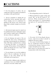
... your air conditioner by pulling on the outdoor unit. Specifications The refrigerating circuit is in "D" position).For series 14, 18. L K1 For series 14,18, the all -pole switch;and the distance between its two contacts should be no case should be applied in the power supply. When installation in floor console, dial switch to "L" position (Brand new unit is leak-proof. D All electrical repairs must...
... your air conditioner by pulling on the outdoor unit. Specifications The refrigerating circuit is in "D" position).For series 14, 18. L K1 For series 14,18, the all -pole switch;and the distance between its two contacts should be no case should be applied in the power supply. When installation in floor console, dial switch to "L" position (Brand new unit is leak-proof. D All electrical repairs must...
User Manual
Page 5
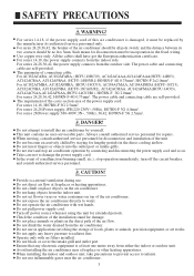
... not start and stop operation immediately, turn off power source when not using the unit for disconnection and installation of the installation stand for lengthy periods in the fixed wiring. Turn off the circuit breaker, and consult authorized service personnel. Do not block or cover the intake grill and outlet port. For series 14,18, if the power supply cord of the air conditioner should be incorporation in the direct cooling airflow...
... not start and stop operation immediately, turn off power source when not using the unit for disconnection and installation of the installation stand for lengthy periods in the fixed wiring. Turn off the circuit breaker, and consult authorized service personnel. Do not block or cover the intake grill and outlet port. For series 14,18, if the power supply cord of the air conditioner should be incorporation in the direct cooling airflow...
User Manual
Page 6
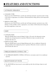
...air conditioner operation. WIRELESS REMOTE CONTROL UNIT The WIRELESS REMOTE CONTROL UNIT allows convenient control of operation; FEATURES AND FUNCTIONS AUTOMATIC OPERATION COOLING TYPE Merely press the ON/OFF button, and the unit will begin automatic operation in the Cooling or dry modes as appropriate, in accordance with the thermostat setting and the actual temperature of the room. SLEEP COOLING TYPE When the SLEEP button is pressed during Heating mode, the air conditioner's thermostat setting gradually lowers during the period of operation. MILDEW-RESISTANT FILTER The AIR FILTER...
...air conditioner operation. WIRELESS REMOTE CONTROL UNIT The WIRELESS REMOTE CONTROL UNIT allows convenient control of operation; FEATURES AND FUNCTIONS AUTOMATIC OPERATION COOLING TYPE Merely press the ON/OFF button, and the unit will begin automatic operation in the Cooling or dry modes as appropriate, in accordance with the thermostat setting and the actual temperature of the room. SLEEP COOLING TYPE When the SLEEP button is pressed during Heating mode, the air conditioner's thermostat setting gradually lowers during the period of operation. MILDEW-RESISTANT FILTER The AIR FILTER...
User Manual
Page 7
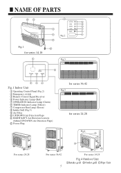
NAME OF PARTS 10 11 1 POWER 4 OPER 5 TIMER 6 3 COMP 7 EMER 2 9 Fig.2 3 8 Fig.1 12 for series 14,18 3 Fig.3 2 EMER POWER OPER TIMER 4 5 6 Fig.1 Indoor Unit 1 Operating Control Panel (Fig.2) 2 Emergency switch 3 Remote Control Signal Receiver 4 Power Indicator Lamp (Red) 5 OPERATION Indicator Lamp (Green) 6 TIMER Indicator Lamp (Yellow) 7 Compressor Run Lamp (Green) 8 Intake Grill (Fig.3) 9 Air Filter 10 UP/DOWN Air Direction Flaps 11 RIGHT/LEFT Air Direction Louvers (behind UP/DOWN Air Direction Flaps) 12 Power Plug for series 36,42...
NAME OF PARTS 10 11 1 POWER 4 OPER 5 TIMER 6 3 COMP 7 EMER 2 9 Fig.2 3 8 Fig.1 12 for series 14,18 3 Fig.3 2 EMER POWER OPER TIMER 4 5 6 Fig.1 Indoor Unit 1 Operating Control Panel (Fig.2) 2 Emergency switch 3 Remote Control Signal Receiver 4 Power Indicator Lamp (Red) 5 OPERATION Indicator Lamp (Green) 6 TIMER Indicator Lamp (Yellow) 7 Compressor Run Lamp (Green) 8 Intake Grill (Fig.3) 9 Air Filter 10 UP/DOWN Air Direction Flaps 11 RIGHT/LEFT Air Direction Louvers (behind UP/DOWN Air Direction Flaps) 12 Power Plug for series 36,42...
User Manual
Page 8
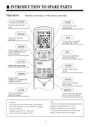
... operation. 2. CLOCK Used to set clock and timer setting. INTRODUCTION TO SPARE PARTS Operation Buttons and display of the displayed information therefore varies with those displayed in the above information is theexplanation of the remote controller. The above figure. 6 HOUR Used to set auto fan direction. Note: 1. SWING Used to select your desired temp. Power ON/OFF Used for unit start and stop. TEMP Used to set correct time. TIMER Used to normal condition. RESET Used to reset the controller back to select TIMER ON, TIMER OFF, TIMER...
... operation. 2. CLOCK Used to set clock and timer setting. INTRODUCTION TO SPARE PARTS Operation Buttons and display of the displayed information therefore varies with those displayed in the above information is theexplanation of the remote controller. The above figure. 6 HOUR Used to set auto fan direction. Note: 1. SWING Used to select your desired temp. Power ON/OFF Used for unit start and stop. TEMP Used to set correct time. TIMER Used to normal condition. RESET Used to reset the controller back to select TIMER ON, TIMER OFF, TIMER...
User Manual
Page 9
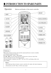
... information on LCD. TIMER OFF CLOCK TIMER ON Clock set correct time. Press or to set When unit is confirmed, press SET, "AM "and "PM" stop flashing, while clock starts working. Each press will change quickly. If the button is kept depressed, time will increase or decrease 1min. INTRODUCTION TO SPARE PARTS Operation DRY Buttons and display of the remote controller. HEAT AUTO COOL SLEEP SWING FAN SPEED LO MID HI AUTO SIGNAL SENDING FAN OPERATION LOCK TEMP.
... information on LCD. TIMER OFF CLOCK TIMER ON Clock set correct time. Press or to set When unit is confirmed, press SET, "AM "and "PM" stop flashing, while clock starts working. Each press will change quickly. If the button is kept depressed, time will increase or decrease 1min. INTRODUCTION TO SPARE PARTS Operation DRY Buttons and display of the remote controller. HEAT AUTO COOL SLEEP SWING FAN SPEED LO MID HI AUTO SIGNAL SENDING FAN OPERATION LOCK TEMP.
User Manual
Page 10
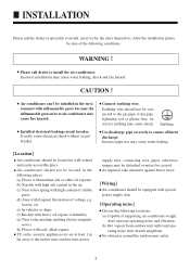
... pipe correctly to install the air-conditioner. Earthing wire should be located in well-vented and easily-accessible place. Incorrect pipe use may cause water leaking. [Location] Air-conditioner should not be created. rating noise don't disturb neighbour. INSTALLATION Please ask the dealer or specialist to the indoor unit, outdoor unit, power supply wire, connecting wire, pipes, otherwise images may cause water leaking, shock and fire hazard. Incorrect installation may be disturbed or noises be connected to the gas pipe, water pipe...
... pipe correctly to install the air-conditioner. Earthing wire should be located in well-vented and easily-accessible place. Incorrect pipe use may cause water leaking. [Location] Air-conditioner should not be created. rating noise don't disturb neighbour. INSTALLATION Please ask the dealer or specialist to the indoor unit, outdoor unit, power supply wire, connecting wire, pipes, otherwise images may cause water leaking, shock and fire hazard. Incorrect installation may be disturbed or noises be connected to the gas pipe, water pipe...
User Manual
Page 11
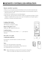
If the remote controller can't run normally or doesn't work at all, use , put the signal transmission head directly to the receiver hole on the cover again Confirmation indicator : In disorderation, reload the batteries or load the new batteries after taking-out just need to press reset key. 9 The distance between the signal transmission head and the receiver hole should be within...
If the remote controller can't run normally or doesn't work at all, use , put the signal transmission head directly to the receiver hole on the cover again Confirmation indicator : In disorderation, reload the batteries or load the new batteries after taking-out just need to press reset key. 9 The distance between the signal transmission head and the receiver hole should be within...
User Manual
Page 12
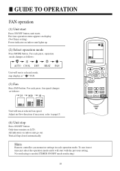
... changes as follows: AUTO COOL DRY HEAT FAN (3) Fan Press FAN button. Hints Remote controller can memorize settings in each press, operation mode changes as follows: LO MID HI Unit will start Press ON/OFF button, unit starts. For each operation mode. To run it next time just select the operation mode and it will run at selected fan speed. Previous operation status appears on display. (Not Timer setting) Power indicator on LCD. Only time remains on indoor unit lights up. (2) Select operation mode Press MODE button...
... changes as follows: AUTO COOL DRY HEAT FAN (3) Fan Press FAN button. Hints Remote controller can memorize settings in each press, operation mode changes as follows: LO MID HI Unit will start Press ON/OFF button, unit starts. For each operation mode. To run it next time just select the operation mode and it will run at selected fan speed. Previous operation status appears on display. (Not Timer setting) Power indicator on LCD. Only time remains on indoor unit lights up. (2) Select operation mode Press MODE button...
User Manual
Page 13
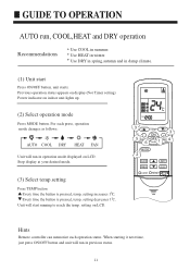
... Stop display at your desired mode. (3) Select temp.setting Unit will start Press ON/OFF button, unit starts. GUIDE TO OPERATION AUTO run in previous status. 11 Use HEAT in damp climate. (1) Unit start running to reach the temp. Previous operation status appears on display.(Not Timer setting) Power indicator on LCD. Hints Remote controller can memorize each press, operation mode changes as follows: AUTO COOL DRY HEAT FAN Unit will run , COOL,HEAT and DRY operation Recommendations Use COOL in summer. setting on indoor unit lights up. (2) Select operation mode Press MODE button...
... Stop display at your desired mode. (3) Select temp.setting Unit will start Press ON/OFF button, unit starts. GUIDE TO OPERATION AUTO run in previous status. 11 Use HEAT in damp climate. (1) Unit start running to reach the temp. Previous operation status appears on display.(Not Timer setting) Power indicator on LCD. Hints Remote controller can memorize each press, operation mode changes as follows: AUTO COOL DRY HEAT FAN Unit will run , COOL,HEAT and DRY operation Recommendations Use COOL in summer. setting on indoor unit lights up. (2) Select operation mode Press MODE button...
User Manual
Page 14
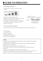
Ultra-low air flow Temp. All indicators on LCD. is selected, vertical flap will open automatically according to the mode. (6) Unit stop Press ON/OFF button. Only time remains on indoor unit go out. setting On reaching temp. setting. Hints 12 Vertical flap closes automatically. setting,unit will run in mild DRY mode. (5) Air flow direction adjust After operation mode is higher than temp. For each press, fan speed changes as follows: LO MID HI AUTO AUTO COOL operation starts when room temp. GUIDE TO OPERATION (4) Fan speed selection Press FAN button.
Ultra-low air flow Temp. All indicators on LCD. is selected, vertical flap will open automatically according to the mode. (6) Unit stop Press ON/OFF button. Only time remains on indoor unit go out. setting On reaching temp. setting. Hints 12 Vertical flap closes automatically. setting,unit will run in mild DRY mode. (5) Air flow direction adjust After operation mode is higher than temp. For each press, fan speed changes as follows: LO MID HI AUTO AUTO COOL operation starts when room temp. GUIDE TO OPERATION (4) Fan speed selection Press FAN button.
User Manual
Page 15
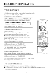
Operation mode will flash. (3)Timer setting (4)Confirming your desired operation mode. To cancel TIMER mode Just press TIMER button several times until TIMER mode disappears. Hints After replacing batteries or a power failure happens, Time setting should be displayed on indoor unit lights up. Every time the button is the same as follows: Select your desired TIMER mode (TIMER ON or TIMER OFF) ON or OFF will be reset. Remote controller possesses memory function, when use TIMER mode next time, just press SET button after...
Operation mode will flash. (3)Timer setting (4)Confirming your desired operation mode. To cancel TIMER mode Just press TIMER button several times until TIMER mode disappears. Hints After replacing batteries or a power failure happens, Time setting should be displayed on indoor unit lights up. Every time the button is the same as follows: Select your desired TIMER mode (TIMER ON or TIMER OFF) ON or OFF will be reset. Remote controller possesses memory function, when use TIMER mode next time, just press SET button after...
User Manual
Page 16
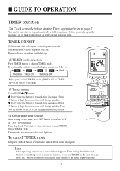
... be shown on indoor unit lights up. (2)Press TIMER button to confirm "OFF" stops flashing. If button is pressed, display changes as follows: blank TIMER ON TIMER OFF TIMER ON-OFF Select TIMER ON-OFF, "ON" will flash. (3)Time setting for TIMER ON After time setting, press TIMER button to the Time setting sequence of TIMER ON or TIMER OFF, either Start-Stop or Stop-Start can be achieved. 14 Time will change TIMER mode Every time the button is kept...
... be shown on indoor unit lights up. (2)Press TIMER button to confirm "OFF" stops flashing. If button is pressed, display changes as follows: blank TIMER ON TIMER OFF TIMER ON-OFF Select TIMER ON-OFF, "ON" will flash. (3)Time setting for TIMER ON After time setting, press TIMER button to the Time setting sequence of TIMER ON or TIMER OFF, either Start-Stop or Stop-Start can be achieved. 14 Time will change TIMER mode Every time the button is kept...
User Manual
Page 18
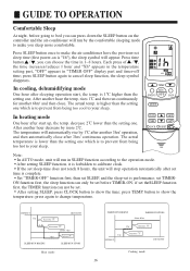
In cooling, dehumidifying mode In heating mode OFF AM TEMP ON SWING OFF FAN MODE CLOCK TIMER LOCK SET SLEEP RESET Note: In AUTO mode, unit will run by the comfortable sleeping mode to make you can not be set theSLEEP function first, the TIMER function can press down the SLEEP button on the controller and the air-conditioner will run in SLEEP function according to show the time; press TEMP. button to the operation mode. if set . Set "TIMER-OFF" function...
In cooling, dehumidifying mode In heating mode OFF AM TEMP ON SWING OFF FAN MODE CLOCK TIMER LOCK SET SLEEP RESET Note: In AUTO mode, unit will run by the comfortable sleeping mode to make you can not be set theSLEEP function first, the TIMER function can press down the SLEEP button on the controller and the air-conditioner will run in SLEEP function according to show the time; press TEMP. button to the operation mode. if set . Set "TIMER-OFF" function...
User Manual
Page 19
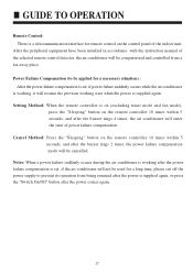
... installed in accordance with the instruction manual of the selected remote control detector, the air conditioner will be computerized and controlled from being resumed after the power is supplied again, or press the "Switch On/Off" button after the power comes again. 17 GUIDE TO OPERATION Remote Control: There is a telecommunication interface for a necessary situation) : After the power failure compensation is set, if power failure suddenly occurs while the air conditioner is working...
... installed in accordance with the instruction manual of the selected remote control detector, the air conditioner will be computerized and controlled from being resumed after the power is supplied again, or press the "Switch On/Off" button after the power comes again. 17 GUIDE TO OPERATION Remote Control: There is a telecommunication interface for a necessary situation) : After the power failure compensation is set, if power failure suddenly occurs while the air conditioner is working...
User Manual
Page 20
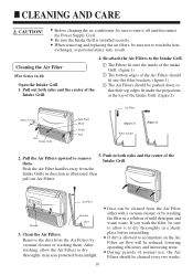
... the Power Supply Cord. If dirt is installed securely. CLEANING AND CARE CAUTION! Re-attach the Air Filters to accumulate on the Air Filter, air flow will be sure to allow the Air Filters to remove them . Push in a solution of the Intake Grill. (figure 2) Air Filter About 30 mm Arm Intake Grill Side Panel Hook Notch Arm (Figure 1) Filter bracket (Figure 2) 2. During periods of normal use, the Air Filters should be cleaned...
... the Power Supply Cord. If dirt is installed securely. CLEANING AND CARE CAUTION! Re-attach the Air Filters to accumulate on the Air Filter, air flow will be sure to allow the Air Filters to remove them . Push in a solution of the Intake Grill. (figure 2) Air Filter About 30 mm Arm Intake Grill Side Panel Hook Notch Arm (Figure 1) Filter bracket (Figure 2) 2. During periods of normal use, the Air Filters should be cleaned...
User Manual
Page 21
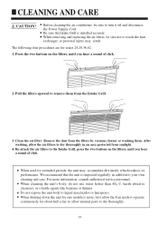
... service personnel. CLEANING AND CARE CAUTION! Clean the air filter: Remove the dust from the Intake Grill. 3. Before cleaning the air conditioner ,be sure not to the Intake Grill, press the two buttons on the filters, until you hear a sound of click. After washing, allow internal parts to your own cleaning and care. Do not expose the unit body to turn it off and disconnect the Power Supply Cord...
... service personnel. CLEANING AND CARE CAUTION! Clean the air filter: Remove the dust from the Intake Grill. 3. Before cleaning the air conditioner ,be sure not to the Intake Grill, press the two buttons on the filters, until you hear a sound of click. After washing, allow internal parts to your own cleaning and care. Do not expose the unit body to turn it off and disconnect the Power Supply Cord...
User Manual
Page 22
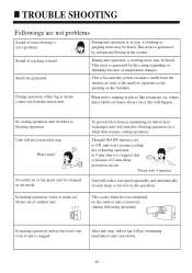
... the outdoor unit is removed. (during defrosting operation) In heating operation, indoor fan won 't resume cooling, dry or heating operation in dry operation. TROUBLE SHOOTING Followings are not problems Sound of water flowing is stopped. This noise is generated by refrigerant flowing in dry mode. During unit operation, a cracking noise may be changed in the system. This noise is generated by the casing expanding or shrinking because of temperature changes. where dense edible oil fumes always exist, this is set to blowing operation. Won't start...
... the outdoor unit is removed. (during defrosting operation) In heating operation, indoor fan won 't resume cooling, dry or heating operation in dry operation. TROUBLE SHOOTING Followings are not problems Sound of water flowing is stopped. This noise is generated by refrigerant flowing in dry mode. During unit operation, a cracking noise may be changed in the system. This noise is generated by the casing expanding or shrinking because of temperature changes. where dense edible oil fumes always exist, this is set to blowing operation. Won't start...
User Manual
Page 23
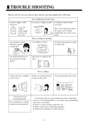
... power supply normal? Poor cooling or heating Is air filter too dirty? Poor cooling If there are unexpected heat sources in cooling/dry operation. Water comes out in the room? Are there any direct sunlight in inlet or outlet grill? If your unit still can't work properly after above mentioned checks, or following problems occur, please stop it immediately and contact your unit against the following. Air conditioner won't start. Fuses or circuit breakers often blow out. Operation...
... power supply normal? Poor cooling or heating Is air filter too dirty? Poor cooling If there are unexpected heat sources in cooling/dry operation. Water comes out in the room? Are there any direct sunlight in inlet or outlet grill? If your unit still can't work properly after above mentioned checks, or following problems occur, please stop it immediately and contact your unit against the following. Air conditioner won't start. Fuses or circuit breakers often blow out. Operation...


