User Manual
Page 2
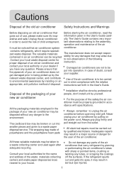
... the waste materials collecting centers and waste paper disposal services nearest to your new air conditioner may be taken to unplug the air conditioner before openning inlet grill. All these valuable materials may be disposed without any parts of your house. erative and safe. The User's Guide contains very impor- If the refrigerant spurts out and gets into eyes, it 's inop- Always...
... the waste materials collecting centers and waste paper disposal services nearest to your new air conditioner may be taken to unplug the air conditioner before openning inlet grill. All these valuable materials may be disposed without any parts of your house. erative and safe. The User's Guide contains very impor- If the refrigerant spurts out and gets into eyes, it 's inop- Always...
User Manual
Page 3
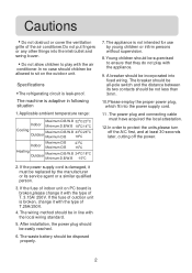
... the air conditioner.In no case should children be allowed to sit on PC board is adaptive in line with the type of the air conditoner.Do not put fingers or any other things into the inlet/outlet and swing louver. If the fuse of indoor unit on the outdoor unit. The wiring method should be incorporated into the power supply cord. 11 .The power plug...
... the air conditioner.In no case should children be allowed to sit on PC board is adaptive in line with the type of the air conditoner.Do not put fingers or any other things into the inlet/outlet and swing louver. If the fuse of indoor unit on the outdoor unit. The wiring method should be incorporated into the power supply cord. 11 .The power plug...
User Manual
Page 4
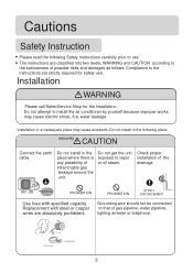
Do not attempt to install the air conditioner by yourself because improper works may cause accidents. Do not install in a inadequate place may cause electric shock, fire, water leakage. Replacement with specified capacity. Compliance to use . Do not install in the following Safety Instructions carefully prior to the instructions are absolutely prohibited. FUSE STEEL WIRE COPPERWIRE 3 Installation in the place where there is any possibility of...
Do not attempt to install the air conditioner by yourself because improper works may cause accidents. Do not install in a inadequate place may cause electric shock, fire, water leakage. Replacement with specified capacity. Compliance to use . Do not install in the following Safety Instructions carefully prior to the instructions are absolutely prohibited. FUSE STEEL WIRE COPPERWIRE 3 Installation in the place where there is any possibility of...
User Manual
Page 7
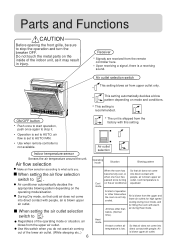
... sleeping etc..) 6 The unit is blown upper air outlet. During Dry mode, so that air does not come into direct contact with people. Air outlet selection Operating mode Situation Blowing pattern Cool mode When the room has become fully cool, or when one hour has passed since turning on mode and conditions. Do not touch the metal parts on the operating mode/situation. Use when remote controller is a receiving sound. Indoor temperature sensor Senses the air temperature around the unit. This setting...
... sleeping etc..) 6 The unit is blown upper air outlet. During Dry mode, so that air does not come into direct contact with people. Air outlet selection Operating mode Situation Blowing pattern Cool mode When the room has become fully cool, or when one hour has passed since turning on mode and conditions. Do not touch the metal parts on the operating mode/situation. Use when remote controller is a receiving sound. Indoor temperature sensor Senses the air temperature around the unit. This setting...

User Manual
Page 9
Remote controller's operation When in use, put the signal transmission head directly to the receiver hole on the cover again. Load the battery: Be sure that the loading is confirmed, press SET, "AM" or "PM" stop flashing, while clock starts working. request as illustrated. Put on the indoor unit. Confirmation indicator: After pressing power ON/OFF, if no display, reload the batteries. Used two new same-typed batteries when loading...
Remote controller's operation When in use, put the signal transmission head directly to the receiver hole on the cover again. Load the battery: Be sure that the loading is confirmed, press SET, "AM" or "PM" stop flashing, while clock starts working. request as illustrated. Put on the indoor unit. Confirmation indicator: After pressing power ON/OFF, if no display, reload the batteries. Used two new same-typed batteries when loading...
User Manual
Page 10
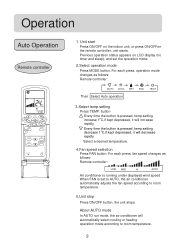
... displayed wind speed When FAN is pressed, temp.setting decrease 1oC,if kept depressed, it will automatically select cooling or heating operation mode according to room temperature. 5.Unit stop Press ON/OFF button, the unit stops. Operation Auto Operation Remote controller 4 5 1. Unit start Press ON/OFF on LCD display (no timer and sleep), and set to AUTO, the air conditioner automatically adjusts the fan speed according to room temperature. 9 For each press, fan speed changes as follows: Remote controller: AUTO COOL DRY FAN Then Select Auto operation HEAT 3.Select temp.setting...
... displayed wind speed When FAN is pressed, temp.setting decrease 1oC,if kept depressed, it will automatically select cooling or heating operation mode according to room temperature. 5.Unit stop Press ON/OFF button, the unit stops. Operation Auto Operation Remote controller 4 5 1. Unit start Press ON/OFF on LCD display (no timer and sleep), and set to AUTO, the air conditioner automatically adjusts the fan speed according to room temperature. 9 For each press, fan speed changes as follows: Remote controller: AUTO COOL DRY FAN Then Select Auto operation HEAT 3.Select temp.setting...
User Manual
Page 11
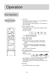
... time the button is set to AUTO, the air conditioner automatically adjusts the fan speed according to room temperature. 5.Unit stop Press ON/OFF button, the unit stops. 10 For each press, fan speed changes as follows: Remote controller: AUTO COOL DRY FAN HEAT Then Select Cool operation 3.Select temp.setting Press TEMP. Unit start Press ON/OFF on LCD display (no timer and sleep). 2.Select operation mode Press MODE button. Previous operation status appears on the indoor unit, or press ON/OFFon the remote controller, unit starts. Operation Cool Operation Remote controller 1. For...
... time the button is set to AUTO, the air conditioner automatically adjusts the fan speed according to room temperature. 5.Unit stop Press ON/OFF button, the unit stops. 10 For each press, fan speed changes as follows: Remote controller: AUTO COOL DRY FAN HEAT Then Select Cool operation 3.Select temp.setting Press TEMP. Unit start Press ON/OFF on LCD display (no timer and sleep). 2.Select operation mode Press MODE button. Previous operation status appears on the indoor unit, or press ON/OFFon the remote controller, unit starts. Operation Cool Operation Remote controller 1. For...
User Manual
Page 12
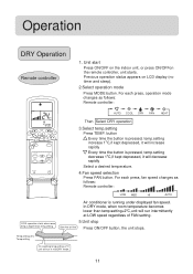
... in mild DRY mode. 11 Operation DRY Operation Remote controller 1. Previous operation status appears on the indoor unit, or press ON/OFFon the remote controller, unit starts. For each press, operation mode changes as follows: Remote controller: LOW MED HI AUTO COOL operation starts when room temp.is higher than temp.setting+2oC,unit will run intermittently at LOW speed regardless of FAN setting. 5.Unit stop Ultra-low air flow Press ON/OFF button, the unit stops. Unit start Press ON/OFF on LCD display (no timer and sleep). 2.Select operation mode Press MODE button.
... in mild DRY mode. 11 Operation DRY Operation Remote controller 1. Previous operation status appears on the indoor unit, or press ON/OFFon the remote controller, unit starts. For each press, operation mode changes as follows: Remote controller: LOW MED HI AUTO COOL operation starts when room temp.is higher than temp.setting+2oC,unit will run intermittently at LOW speed regardless of FAN setting. 5.Unit stop Ultra-low air flow Press ON/OFF button, the unit stops. Unit start Press ON/OFF on LCD display (no timer and sleep). 2.Select operation mode Press MODE button.

User Manual
Page 13
...4.Unit stop Press ON/OFF button, the unit stops. For each press, fan speed changes as follows: Remote controller: AUTO COOL DRY FAN Then Select FAN operation HEAT 3.Fan speed selection Press FAN button. And temp. Previous operation status appears on the indoor unit, or press ON/OFFon the remote controller, unit starts. In FAN mode, SLEEP operation is disabled. setting is not available. 12 Unit start Press ON/OFF on LCD display (no timer and sleep). 2.Select operation mode Press MODE button. Operation FAN Operation Remote controller 1. AUTO is not available in FAN mode...
...4.Unit stop Press ON/OFF button, the unit stops. For each press, fan speed changes as follows: Remote controller: AUTO COOL DRY FAN Then Select FAN operation HEAT 3.Fan speed selection Press FAN button. And temp. Previous operation status appears on the indoor unit, or press ON/OFFon the remote controller, unit starts. In FAN mode, SLEEP operation is disabled. setting is not available. 12 Unit start Press ON/OFF on LCD display (no timer and sleep). 2.Select operation mode Press MODE button. Operation FAN Operation Remote controller 1. AUTO is not available in FAN mode...
User Manual
Page 14
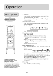
...the time due to room temperature. 5.Unit stop Press ON/OFF button, the unit stops. 13 For each press, operation mode changes as follows: Remote controller: LOW MED HI AUTO Air conditioner is pressed, temp.setting decrease 1oC,if kept depressed, it will increase rapidly Every time the button is running under cooling mode. Unit start Press ON/OFF on LCD display (no timer and sleep). 2.Select operation mode Press MODE button. AUTO COOL DRY FAN HEAT Then Select HEAT operation 3.Select temp.setting Press TEMP. Operation HEAT Operation Remote controller 1. When FAN is normal...
...the time due to room temperature. 5.Unit stop Press ON/OFF button, the unit stops. 13 For each press, operation mode changes as follows: Remote controller: LOW MED HI AUTO Air conditioner is pressed, temp.setting decrease 1oC,if kept depressed, it will increase rapidly Every time the button is running under cooling mode. Unit start Press ON/OFF on LCD display (no timer and sleep). 2.Select operation mode Press MODE button. AUTO COOL DRY FAN HEAT Then Select HEAT operation 3.Select temp.setting Press TEMP. Operation HEAT Operation Remote controller 1. When FAN is normal...

User Manual
Page 16
... COOL,DRY mode 15 The sleep time can simply press the SLEEP button and unit will run for your sleep. 2. Operation Mode 1. In HEAT mode 3 hours after SLEEP mode starts, temperature will run is expired. 3 hr Rises 1oC 3 hr Rises 1oC Temperature setting Unit stop Approx. 2 hrs Remote controller SLEEP operation starts In HEAT mode SLEEP operation stops 3. Push the SLEEP button. Use of 1-8 hours. It will display " ", and display the timing off and detail off function. 5. After another 3 hours temperature decrease by 1oC further. In AUTO mode...
... COOL,DRY mode 15 The sleep time can simply press the SLEEP button and unit will run for your sleep. 2. Operation Mode 1. In HEAT mode 3 hours after SLEEP mode starts, temperature will run is expired. 3 hr Rises 1oC 3 hr Rises 1oC Temperature setting Unit stop Approx. 2 hrs Remote controller SLEEP operation starts In HEAT mode SLEEP operation stops 3. Push the SLEEP button. Use of 1-8 hours. It will display " ", and display the timing off and detail off function. 5. After another 3 hours temperature decrease by 1oC further. In AUTO mode...
User Manual
Page 20
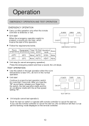
... you can hear, which means the start of this switch in the normal operation. TEST OPERATION Use this operation. Room Designated temperature temperature Timer mode Air flow speed Operation mode Anion >23oC 26oC None AUTO COOL None *23oC 23oC None AUTO HEAT None EMERGENCY SWITCH Unit stop (to cancel the test run as per the working mode displayed on the remote controller. 19 ON/OFF TEST SWITCH Unit stop (to press the test operation switch for more than 5 seconds. After you...
... you can hear, which means the start of this switch in the normal operation. TEST OPERATION Use this operation. Room Designated temperature temperature Timer mode Air flow speed Operation mode Anion >23oC 26oC None AUTO COOL None *23oC 23oC None AUTO HEAT None EMERGENCY SWITCH Unit stop (to cancel the test run as per the working mode displayed on the remote controller. 19 ON/OFF TEST SWITCH Unit stop (to press the test operation switch for more than 5 seconds. After you...

User Manual
Page 23
... and outlet to ensure the electrostatic filters not soiled. Clean the filter and indoor, outdoor unit, cover the units well. Otherwise,dirt will be started and operate in FAN mode for about half a day unit the inside of the unit becomes thoroughly dry. Maintenance Maintenance at the end of application season On a fine day, unit shall be some electricity consumption even the unit is in stop status. Turn off the unit operation switch and power on/off.
... and outlet to ensure the electrostatic filters not soiled. Clean the filter and indoor, outdoor unit, cover the units well. Otherwise,dirt will be started and operate in FAN mode for about half a day unit the inside of the unit becomes thoroughly dry. Maintenance Maintenance at the end of application season On a fine day, unit shall be some electricity consumption even the unit is in stop status. Turn off the unit operation switch and power on/off.
User Manual
Page 24
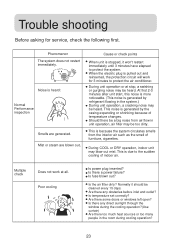
... COOL or DRY operation, indoor unit may be heard. Is temperature set correctly? Cause or check points When unit is generated by refrigerant flowing in the room during cooling operation? 23 Is the air filter dirty? Are there some doors or windows left open? Multiple check Does not work for service, check the following first. When the electric plug is generated by the casing expanding or shrinking because of temperature changes. Trouble shooting Before...
... COOL or DRY operation, indoor unit may be heard. Is temperature set correctly? Cause or check points When unit is generated by refrigerant flowing in the room during cooling operation? 23 Is the air filter dirty? Are there some doors or windows left open? Multiple check Does not work for service, check the following first. When the electric plug is generated by the casing expanding or shrinking because of temperature changes. Trouble shooting Before...
User Manual
Page 25
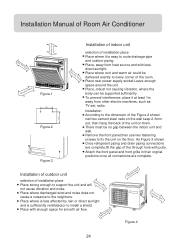
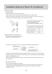
... route drainage pipe and outdoor piping. Place near power supply socket.Leave enough space around the unit. Place, robust not causing vibration, where the body can be no gap between the indoor unit and wall. Installation According to the dimension of the Figure 2 shown nail two cement steel nails on the floor. Remove the front panel,then use two fastening screws to install a shield. Installation Manual of Room Air Conditioner...
... route drainage pipe and outdoor piping. Place near power supply socket.Leave enough space around the unit. Place, robust not causing vibration, where the body can be no gap between the indoor unit and wall. Installation According to the dimension of the Figure 2 shown nail two cement steel nails on the floor. Remove the front panel,then use two fastening screws to install a shield. Installation Manual of Room Air Conditioner...
User Manual
Page 26
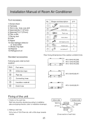
Making a wall hole Drill a hole of Room Air Conditioner Tool necessary 1.Screw driver 2.Hacksaw 3.70mm dia. Installation Manual of 120x70mm dia. Shape and description QTY Remote controller 1 Drain hose 1 Plastic cap 4 Drain-elbow 1 Self-tapping screw 4 Rubber pad 4 dry battery #7 2 Floor fixing dimensions of the outdoor unit(Unit:mm) HFU-09H03/R2(DB) 256 HFU-12H03/R2(DB) HFU-18H03/R2(DB) 140 500 140 310 HFU-09HA03(B)/R1 105 500 105 310 105 550...
Making a wall hole Drill a hole of Room Air Conditioner Tool necessary 1.Screw driver 2.Hacksaw 3.70mm dia. Installation Manual of 120x70mm dia. Shape and description QTY Remote controller 1 Drain hose 1 Plastic cap 4 Drain-elbow 1 Self-tapping screw 4 Rubber pad 4 dry battery #7 2 Floor fixing dimensions of the outdoor unit(Unit:mm) HFU-09H03/R2(DB) 256 HFU-12H03/R2(DB) HFU-18H03/R2(DB) 140 500 140 310 HFU-09HA03(B)/R1 105 500 105 310 105 550...
User Manual
Page 27
... drainage pipe Remove the cover before working. To bent a pipe, give the roundness as large as possible not to let foreign matters, such as per the wall hole and bind drain hose connecting electric cable and piping together with a hammer or a saw, the lid for indoor and outdoor unit According to Fig. Forced fastening without careful centering may damage the threads and cause a leakage of Room Air Conditioner...
... drainage pipe Remove the cover before working. To bent a pipe, give the roundness as large as possible not to let foreign matters, such as per the wall hole and bind drain hose connecting electric cable and piping together with a hammer or a saw, the lid for indoor and outdoor unit According to Fig. Forced fastening without careful centering may damage the threads and cause a leakage of Room Air Conditioner...
User Manual
Page 28
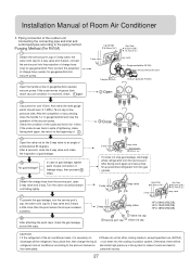
... 3-way valve HFU-09H03/R2(DB) HFU-12H03/R2(DB) HFU-18H03/R2(DB) Service port cap Valve rod cap Valve rod cap CAUTION: 1.If the refrigerant of the air conditioner leaks, it does not stop the operation of charge hose (low) for 1-2min. Installation Manual of gause (low) reach vacuum condition in a moment, check again. In case of gas leakage, tighten parts of gas leakage...
... 3-way valve HFU-09H03/R2(DB) HFU-12H03/R2(DB) HFU-18H03/R2(DB) Service port cap Valve rod cap Valve rod cap CAUTION: 1.If the refrigerant of the air conditioner leaks, it does not stop the operation of charge hose (low) for 1-2min. Installation Manual of gause (low) reach vacuum condition in a moment, check again. In case of gas leakage, tighten parts of gas leakage...
User Manual
Page 30
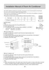
... : 3G2.5mm2+1x0.75mm2 Wiring of outdoor unit Insert the cable from front. Replace cover after wiring. Pull it out from inside the wall hole where piping already exist. Incorrect wiring may damage air conditioner's control or cause operation failure. 29 Installation Manual of Room Air Conditioner Note: When additional refrigerant is necessary, first purge air out of same number and same color shall be done by the same wire. Brand new unit is tight. Loose...
... : 3G2.5mm2+1x0.75mm2 Wiring of outdoor unit Insert the cable from front. Replace cover after wiring. Pull it out from inside the wall hole where piping already exist. Incorrect wiring may damage air conditioner's control or cause operation failure. 29 Installation Manual of Room Air Conditioner Note: When additional refrigerant is necessary, first purge air out of same number and same color shall be done by the same wire. Brand new unit is tight. Loose...
User Manual
Page 31
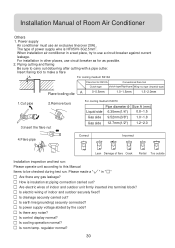
... run. Installation Manual of indoor and outdoor unit firmly inserted into terminal block? The type of power supply wire is insulation at piping connection carried out? Are electric wires of Room Air Conditioner Others 1. Is room temp. For installation in " " Are there any noise? Is earth line(grounding) securely connected? Power supply Air conditioner must use a circuit breaker against current leakage. Is drainage securely carried out? Is power supply voltage abided by the code? When installation air conditioner in a wet...
... run. Installation Manual of indoor and outdoor unit firmly inserted into terminal block? The type of power supply wire is insulation at piping connection carried out? Are electric wires of Room Air Conditioner Others 1. Is room temp. For installation in " " Are there any noise? Is earth line(grounding) securely connected? Power supply Air conditioner must use a circuit breaker against current leakage. Is drainage securely carried out? Is power supply voltage abided by the code? When installation air conditioner in a wet...


