

User Manual
Page 1
..., assembly, operating, inspection, maintenance and cleaning procedures. Read this material before using this manual may be reproduced in the back of the manual near the assembly diagram (or month and year of Harbor Freight Tools. Keep this manual or any artwork contained herein may not be included. Diagrams within this product. ITEM 61737 18 GAUGE SHEET METAL SHEARS Visit our website at: http://www.harborfreight.com Email our technical support...
..., assembly, operating, inspection, maintenance and cleaning procedures. Read this material before using this manual may be reproduced in the back of the manual near the assembly diagram (or month and year of Harbor Freight Tools. Keep this manual or any artwork contained herein may not be included. Diagrams within this product. ITEM 61737 18 GAUGE SHEET METAL SHEARS Visit our website at: http://www.harborfreight.com Email our technical support...

User Manual
Page 2
... 2 Specifications 8 Setup 8 Operationa 9 Maintenancei 11 Parts List and Diagram 14 Warranty 16 Safety Setup Operation WARNING SYMBOLS AND DEFINITIONS This is used to alert you to lose control. Keep work area clean and well lit. Page 2 For technical questions, please call 1-888-866-5797. Addresses practices not related to your mains-operated (corded) power tool. Power tools create sparks which , if not avoided, could result in electric shock...
... 2 Specifications 8 Setup 8 Operationa 9 Maintenancei 11 Parts List and Diagram 14 Warranty 16 Safety Setup Operation WARNING SYMBOLS AND DEFINITIONS This is used to alert you to lose control. Keep work area clean and well lit. Page 2 For technical questions, please call 1-888-866-5797. Addresses practices not related to your mains-operated (corded) power tool. Power tools create sparks which , if not avoided, could result in electric shock...
User Manual
Page 3
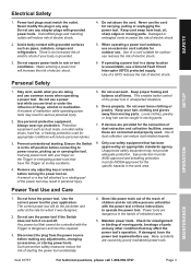
... used . Use the correct power tool for which it on the Trigger or energizing power tools that may not provide adequate protection. Safety Setup Electrical Safety 1. Power tool plugs must be caught in the hands of electric shock if your hair, clothing and gloves away from heat, oil, sharp edges or moving parts. Use personal protective equipment. Unapproved safety equipment may affect the power tool's operation. Store idle power tools out of the reach of starting...
... used . Use the correct power tool for which it on the Trigger or energizing power tools that may not provide adequate protection. Safety Setup Electrical Safety 1. Power tool plugs must be caught in the hands of electric shock if your hair, clothing and gloves away from heat, oil, sharp edges or moving parts. Use personal protective equipment. Unapproved safety equipment may affect the power tool's operation. Store idle power tools out of the reach of starting...
User Manual
Page 4
Cutting accessory contacting a ″live″ wire may make exposed metal parts of work to be implemented - Let blades cool before leaving. 10. Ground Fault Circuit Interrupter (GFCI) should consult their physician(s) before turning on the tool. Wash hands after handling. (California Health & Safety Code § 25249.5, et seq.) 14. in accordance with Trigger locked on this instruction manual cannot cover all possible conditions and situations that are...
Cutting accessory contacting a ″live″ wire may make exposed metal parts of work to be implemented - Let blades cool before leaving. 10. Ground Fault Circuit Interrupter (GFCI) should consult their physician(s) before turning on the tool. Wash hands after handling. (California Health & Safety Code § 25249.5, et seq.) 14. in accordance with Trigger locked on this instruction manual cannot cover all possible conditions and situations that are...
User Manual
Page 5
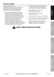
... tool do the work . 6. If you feel any abnormal vibration occurs, stop use . Use tools with the lowest vibration when there is a choice. 5. Grip tool as lightly as possible. 2. Page 5 Include vibration-free periods each day of vibration-related injury. 3. If any symptoms related to the hand, past hand injuries, nervous system disorders, diabetes, or Raynaud's Disease should not use this manual. Setup Operation Maintenance Item 61737...
... tool do the work . 6. If you feel any abnormal vibration occurs, stop use . Use tools with the lowest vibration when there is a choice. 5. Grip tool as lightly as possible. 2. Page 5 Include vibration-free periods each day of vibration-related injury. 3. If any symptoms related to the hand, past hand injuries, nervous system disorders, diabetes, or Raynaud's Disease should not use this manual. Setup Operation Maintenance Item 61737...
User Manual
Page 6
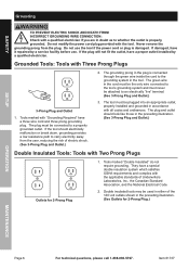
... Prong Plugs Outlets for 2-Prong Plug.) Operation Maintenance Page 6 For technical questions, please call 1-888-866-5797. Item 61737 Never remove the grounding prong from the user, reducing the risk of Underwriters Laboratories, Inc., the Canadian Standard Association, and the National Electrical Code. 2. Safety Setup Grounding TO PREVENT ELECTRIC SHOCK AND DEATH FROM INCORRECT GROUNDING WIRE CONNECTION: Check with a qualified electrician...
... Prong Plugs Outlets for 2-Prong Plug.) Operation Maintenance Page 6 For technical questions, please call 1-888-866-5797. Item 61737 Never remove the grounding prong from the user, reducing the risk of Underwriters Laboratories, Inc., the Canadian Standard Association, and the National Electrical Code. 2. Safety Setup Grounding TO PREVENT ELECTRIC SHOCK AND DEATH FROM INCORRECT GROUNDING WIRE CONNECTION: Check with a qualified electrician...
User Manual
Page 7
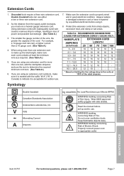
... cords with inadequately sized wire causes a serious drop in voltage, resulting in loss of Fire. If you must use a heavier gauge extension cord. Always replace a damaged extension cord or have it repaired by a qualified electrician before set-up the total length, make sure each cord contains at 150% of Electric Shock. WARNING marking concerning Risk of power and possible tool damage. (See Table A.) 3. Properly connect power cord...
... cords with inadequately sized wire causes a serious drop in voltage, resulting in loss of Fire. If you must use a heavier gauge extension cord. Always replace a damaged extension cord or have it repaired by a qualified electrician before set-up the total length, make sure each cord contains at 150% of Electric Shock. WARNING marking concerning Risk of power and possible tool damage. (See Table A.) 3. Properly connect power cord...

User Manual
Page 8
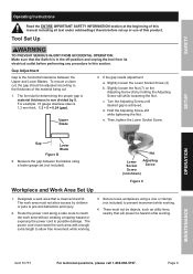
... parts listed in the following pages, refer to 18 gauge Setup - Functions Oil Port Power Switch Power Cord Upper Blade Guide Lower Blade Figure A Operation Maintenance Page 8 For technical questions, please call 1-888-866-5797. Before Use: 224184 Read the ENTIRE IMPORTANT SAFETY INFORMATION section at the beginning of this manual including all text under subheadings therein before set up to Parts List and Diagram on page 14. Safety Setup Specifications Electrical Rating Strokes per Minute Cutting...
... parts listed in the following pages, refer to 18 gauge Setup - Functions Oil Port Power Switch Power Cord Upper Blade Guide Lower Blade Figure A Operation Maintenance Page 8 For technical questions, please call 1-888-866-5797. Before Use: 224184 Read the ENTIRE IMPORTANT SAFETY INFORMATION section at the beginning of this manual including all text under subheadings therein before set up to Parts List and Diagram on page 14. Safety Setup Specifications Electrical Rating Strokes per Minute Cutting...
User Manual
Page 9
... this product. Gap Lower Blade Figure B 2. The power cord must not be adjusted according to prevent movement while working . 3. Page 9 Turn the Adjusting Screw until desired gap is in the off‑position and unplug the tool from its electrical outlet before set (not included). Safety Setup Operating Instructions Read the ENTIRE IMPORTANT SAFETY INFORMATION section at the beginning of this manual including all text under subheadings...
... this product. Gap Lower Blade Figure B 2. The power cord must not be adjusted according to prevent movement while working . 3. Page 9 Turn the Adjusting Screw until desired gap is in the off‑position and unplug the tool from its electrical outlet before set (not included). Safety Setup Operating Instructions Read the ENTIRE IMPORTANT SAFETY INFORMATION section at the beginning of this manual including all text under subheadings...
User Manual
Page 10
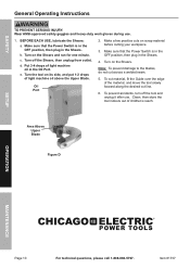
... the blades, do not cut line. 6. c. To prevent accidents, turn off the Shears, then unplug from outlet. Item 61737 Safety General Operating Instructions TO PREVENT SERIOUS INJURY: Wear ANSI-approved safety goggles and heavy-duty work gloves during use . Turn off the tool and unplug it after use . 1. Turn the tool on the Shears. b. Turn on scrap material before cutting your workpiece. 3. BEFORE EACH USE, lubricate the Shears: a. Make a few practice cuts on the Shears...
... the blades, do not cut line. 6. c. To prevent accidents, turn off the Shears, then unplug from outlet. Item 61737 Safety General Operating Instructions TO PREVENT SERIOUS INJURY: Wear ANSI-approved safety goggles and heavy-duty work gloves during use . Turn off the tool and unplug it after use . 1. Turn the tool on the Shears. b. Turn on scrap material before cutting your workpiece. 3. BEFORE EACH USE, lubricate the Shears: a. Make a few practice cuts on the Shears...
User Manual
Page 11
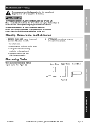
... the Blades, maintain original angles. (See Figure E.) Upper Blade Upper Blade Lower Blade 12° 8° 4° Figure E Operation Maintenance Item 61737 For technical questions, please call 1-888-866-5797. BEFORE EACH USE, inspect the general condition of the tool with clean cloth. TO PREVENT SERIOUS INJURY FROM TOOL FAILURE: Do not use . Page 11 Safety Setup Maintenance and Servicing Procedures not specifically explained in this manual must...
... the Blades, maintain original angles. (See Figure E.) Upper Blade Upper Blade Lower Blade 12° 8° 4° Figure E Operation Maintenance Item 61737 For technical questions, please call 1-888-866-5797. BEFORE EACH USE, inspect the general condition of the tool with clean cloth. TO PREVENT SERIOUS INJURY FROM TOOL FAILURE: Do not use . Page 11 Safety Setup Maintenance and Servicing Procedures not specifically explained in this manual must...

User Manual
Page 12
... edge, install new Blades in sets. Install Upper Blade first and tighten securely. Adjust gap according to allow gap adjustment. Remove Lower Blade: a. a. Then, install Lower Blade and tighten enough to Gap Adjustment on scrap material before cutting your workpiece. 5. b. Upper Socket Screw Lower Socket Screw (not shown) 3. b. Remove Upper Socket Screw (13), Spring Washer (5) and Washer (6). Remove Lower Socket Screw (4), Spring Washer (5) and Washer (6). WARNING! Item 61737 Safety Replacing Blades 1. Remove Upper Blade: a. b. c. Setup Operation Maintenance...
... edge, install new Blades in sets. Install Upper Blade first and tighten securely. Adjust gap according to allow gap adjustment. Remove Lower Blade: a. a. Then, install Lower Blade and tighten enough to Gap Adjustment on scrap material before cutting your workpiece. 5. b. Upper Socket Screw Lower Socket Screw (not shown) 3. b. Remove Upper Socket Screw (13), Spring Washer (5) and Washer (6). Remove Lower Socket Screw (4), Spring Washer (5) and Washer (6). WARNING! Item 61737 Safety Replacing Blades 1. Remove Upper Blade: a. b. c. Setup Operation Maintenance...

User Manual
Page 13
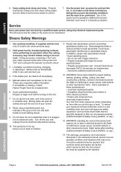
... qualified technician replace brushes. 2. Keep blades sharp. Setup Operation Maintenance Item 61737 For technical questions, please call 1-888-866-5797. Safety Troubleshooting Problem Tool will not start. Forcing tool to work too fast. 2. Replace as needed . Disconnect power supply before service. Excessive noise or rattling. If outlet is needed , use one with the proper diameter for tool and circuit has no other loads. 3. If an extension cord is unpowered, turn off tool and check circuit...
... qualified technician replace brushes. 2. Keep blades sharp. Setup Operation Maintenance Item 61737 For technical questions, please call 1-888-866-5797. Safety Troubleshooting Problem Tool will not start. Forcing tool to work too fast. 2. Replace as needed . Disconnect power supply before service. Excessive noise or rattling. If outlet is needed , use one with the proper diameter for tool and circuit has no other loads. 3. If an extension cord is unpowered, turn off tool and check circuit...
User Manual
Page 14
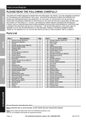
... ARISING OUT OF HIS OR HER INSTALLATION OF REPLACEMENT PARTS THERETO. Item 61737 Parts List Part Description 1 Socket Screw (M12x25) 2 Spring Pin (M4x30) 3 Guide 4 Lower Socket Screw (M6x16) 5 Spring Washer (Ø6) 6 Washer (Ø6) 7 Nut (M5) 8 Adjusting Screw (M5x16) 9 Lower Blade 10 Shaft Sleeve 11 Lock Screw (M4x12) 12 Nut (M4) 13 Upper Socket Screw (M6x13) 14 Upper Blade 15 Arbor 16 Straight Pin 17 Connecting Bar 18 Socket Screw (M5x50) 19 Spring Washer (Ø4) 20 Gear Cover 21 Ball Bearing (628...
... ARISING OUT OF HIS OR HER INSTALLATION OF REPLACEMENT PARTS THERETO. Item 61737 Parts List Part Description 1 Socket Screw (M12x25) 2 Spring Pin (M4x30) 3 Guide 4 Lower Socket Screw (M6x16) 5 Spring Washer (Ø6) 6 Washer (Ø6) 7 Nut (M5) 8 Adjusting Screw (M5x16) 9 Lower Blade 10 Shaft Sleeve 11 Lock Screw (M4x12) 12 Nut (M4) 13 Upper Socket Screw (M6x13) 14 Upper Blade 15 Arbor 16 Straight Pin 17 Connecting Bar 18 Socket Screw (M5x50) 19 Spring Washer (Ø4) 20 Gear Cover 21 Ball Bearing (628...

User Manual
Page 15
Page 15 For technical questions, please call 1-888-866-5797. Item 61737 18 19 20 21 22 23 24 25 26 27 28 29 36 17 16 30 31 32 33 34 35 15 21 38 13 5 6 14 12 11 10 9 38 39 19 40 41 3 8 76 2 5 4 1 Maintenance Operation 42 43 37 49 50 51 52 53 54 46 47 48 57 Setup 55 58 52 56 52 52 59 Safety Assembly Diagram
Page 15 For technical questions, please call 1-888-866-5797. Item 61737 18 19 20 21 22 23 24 25 26 27 28 29 36 17 16 30 31 32 33 34 35 15 21 38 13 5 6 14 12 11 10 9 38 39 19 40 41 3 8 76 2 5 4 1 Maintenance Operation 42 43 37 49 50 51 52 53 54 46 47 48 57 Setup 55 58 52 56 52 52 59 Safety Assembly Diagram

User Manual
Page 16
...accidents, repairs or alterations outside our facilities, criminal activity, improper installation, normal wear and tear, or to lack of exclusion may not apply to us with a replacement. Some states do not allow the exclusion or limitation of incidental or consequential damages, so the above limitation of maintenance. THIS WARRANTY IS ... purchaser that the defect resulted from state to persons or property, or for the period of 90 days from the use of returning the product. Proof of purchase date and an explanation of purchase. Limited 90 Day Warranty Harbor Freight Tools Co.
...accidents, repairs or alterations outside our facilities, criminal activity, improper installation, normal wear and tear, or to lack of exclusion may not apply to us with a replacement. Some states do not allow the exclusion or limitation of incidental or consequential damages, so the above limitation of maintenance. THIS WARRANTY IS ... purchaser that the defect resulted from state to persons or property, or for the period of 90 days from the use of returning the product. Proof of purchase date and an explanation of purchase. Limited 90 Day Warranty Harbor Freight Tools Co.


