
Owners Manual
Page 1
r rt t....fnrin _ ,1, E llEMEEril S:1,7,11 That VGA.. 'Hy FM Sr ,n -/- Volume Loudriess Treble .C, ,,t5f/CO harman/kardon Audio and Video Receiver OWNER'S MANUAL 111 I a II II III II WM III II a II II II II IIIMM II ill Al7R20 II nCM MDn m, AM O 0 0:0 0 x,„ cznt.
r rt t....fnrin _ ,1, E llEMEEril S:1,7,11 That VGA.. 'Hy FM Sr ,n -/- Volume Loudriess Treble .C, ,,t5f/CO harman/kardon Audio and Video Receiver OWNER'S MANUAL 111 I a II II III II WM III II a II II II II IIIMM II ill Al7R20 II nCM MDn m, AM O 0 0:0 0 x,„ cznt.
Owners Manual
Page 2
... to the presence of uninsulated "dangerous voltage" within the product's enclosure that will give you years of superb performance. and Canadian customers should use voltages appropriate to the point of important operating and maintenance (servicing) instructions in particular, specifies that provides guidelines for choosing a Harman Kardon AudioNideo Receiver. CAUTION RISK OF ELECTRIC SHOCK DO NOT OPEN CAUTION: TO...
... to the presence of uninsulated "dangerous voltage" within the product's enclosure that will give you years of superb performance. and Canadian customers should use voltages appropriate to the point of important operating and maintenance (servicing) instructions in particular, specifies that provides guidelines for choosing a Harman Kardon AudioNideo Receiver. CAUTION RISK OF ELECTRIC SHOCK DO NOT OPEN CAUTION: TO...
Owners Manual
Page 3
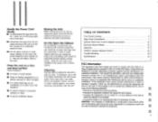
... the receiver is connected. • Consult the dealer or an experienced radio TV technician for a Class B digital device, pursuant to Part 15 of the FCC Rules. Place the unit on a firm and level surface. Do Not Open the Cabinet. TABLE OF CONTENTS Front Panel Controls 3 Rear Panel Connedtions 7 Optional Multi-room Control Adapter Connection 10 Surround Sound Effects 13 Operation 15 AVR20 II System Remote Control 16 Trouble Shooting 18 Specifications 19...
... the receiver is connected. • Consult the dealer or an experienced radio TV technician for a Class B digital device, pursuant to Part 15 of the FCC Rules. Place the unit on a firm and level surface. Do Not Open the Cabinet. TABLE OF CONTENTS Front Panel Controls 3 Rear Panel Connedtions 7 Optional Multi-room Control Adapter Connection 10 Surround Sound Effects 13 Operation 15 AVR20 II System Remote Control 16 Trouble Shooting 18 Specifications 19...
Owners Manual
Page 4
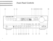
B - `` AM ...0,,, wir`!M'fr,u" ..- m 3TSEREO Dm .CENTER MODE, =MI EIMI SEARCH TAPE MONITOR VCR 1 DUBBING M=Calli Tuning AM FM FM Mono Search Volume Loudness 0 Power Surround Test Tape 1 VCR 1 Tuner CD Bass Headphones Speakers 0000 1' X VCR 2 VCR 1 Center Tape L Mon VCR 2 TV/Aux Phono Treble Balance VCR 2 0 0 0 T 3 ® CD CDOC)®®g 0 CD 0 CD Front Panel Controls 17 CD CD 25 CD'OCD® 24 23 harman/kardon AVR 20 11 0 O 0 Lc P Scan 0-30 Memory =MI OEM 8 8B.88 .z saT.8-
B - `` AM ...0,,, wir`!M'fr,u" ..- m 3TSEREO Dm .CENTER MODE, =MI EIMI SEARCH TAPE MONITOR VCR 1 DUBBING M=Calli Tuning AM FM FM Mono Search Volume Loudness 0 Power Surround Test Tape 1 VCR 1 Tuner CD Bass Headphones Speakers 0000 1' X VCR 2 VCR 1 Center Tape L Mon VCR 2 TV/Aux Phono Treble Balance VCR 2 0 0 0 T 3 ® CD CDOC)®®g 0 CD 0 CD Front Panel Controls 17 CD CD 25 CD'OCD® 24 23 harman/kardon AVR 20 11 0 O 0 Lc P Scan 0-30 Memory =MI OEM 8 8B.88 .z saT.8-
Owners Manual
Page 5
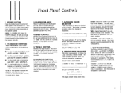
... channels as much as +/- 10dB. SURROUND MODE SELECTOR Press this switch to -large center speaker. The mode is changed as a system power button, if you connect the other components to the receiver, no sound will light up orange and power is reproduced from the right speaker. 7. The display window shows TEST L, C, R and S in DOLBY PRO-LOGIC and DOLBY 3 STEREO mode. TREBLE CONTROL Modifies the high-frequency sound of the left speaker, counterclockwise rotation reduces the volume from the front speakers...
... channels as much as +/- 10dB. SURROUND MODE SELECTOR Press this switch to -large center speaker. The mode is changed as a system power button, if you connect the other components to the receiver, no sound will light up orange and power is reproduced from the right speaker. 7. The display window shows TEST L, C, R and S in DOLBY PRO-LOGIC and DOLBY 3 STEREO mode. TREBLE CONTROL Modifies the high-frequency sound of the left speaker, counterclockwise rotation reduces the volume from the front speakers...
Owners Manual
Page 6
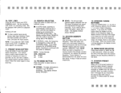
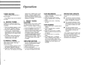
... MANUAL mode, the frequency is released. FM/AM BAND SELECTOR Press these buttons to scan the preset station frequencies. Press this button to stop scanning. 12. The display window shows `SEARCH'. STATION MEMORY BUTTON Use this button again to store an AM or FM frequency. To select preset 30, simply press "0". 5 Dubbing will start. ■ To hear another input source during VCR 1 DUBBING, the audio signal is disconnected from AC power for...
... MANUAL mode, the frequency is released. FM/AM BAND SELECTOR Press these buttons to scan the preset station frequencies. Press this button to stop scanning. 12. The display window shows `SEARCH'. STATION MEMORY BUTTON Use this button again to store an AM or FM frequency. To select preset 30, simply press "0". 5 Dubbing will start. ■ To hear another input source during VCR 1 DUBBING, the audio signal is disconnected from AC power for...

Owners Manual
Page 7
... Phono. 20. VOLUME LEVEL INDICATOR This indicator moves in . It also contains the IR Remote Sensor. ■ 6 TAPE 2 MONITOR BUTTON Set TAPE 2 MONITOR to the "off" position when you want to the TAPE 2 MON input jacks. 19. In the OFF position, the frequency response is changed at low listening levels (known as the Fletcher-Munson hearing curve). This button does not work at all volume levels. The volume of the receiver. DISPLAY...
... Phono. 20. VOLUME LEVEL INDICATOR This indicator moves in . It also contains the IR Remote Sensor. ■ 6 TAPE 2 MONITOR BUTTON Set TAPE 2 MONITOR to the "off" position when you want to the TAPE 2 MON input jacks. 19. In the OFF position, the frequency response is changed at low listening levels (known as the Fletcher-Munson hearing curve). This button does not work at all volume levels. The volume of the receiver. DISPLAY...

Owners Manual
Page 8
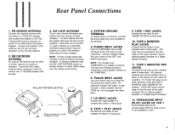
....ARAIORGAO2N.EL0011US8GOEHMM0SINPEAKER1S9 17 HITG PLA PL *LAY OUT e RIGFSROPE9 A ACOUTLETS SWITCHED wax OR I I.VA ACIPOWOORs 22 OATTIOCRAIIEOKPLnWM.O%/MAWXOIPMOIlt POWER AMPLIFIER SUBWOOFER 5 COMPACT DISC PLAYER 6 7 10 8 9 11 CASSETTE DECK 1 RINECPOULT AY TO WALL OUTLET AUDIO OUT OUT RINECPOULTAY REAR SPEAKERS VCR 2 FRONT SPEAKERS TO WALL OUTLET C..8AFTTF nEri< ? REMOTE IN OUT VIDEAOUDIO CL CR OUT OUT VINC-2R PLAY TO WALL OUTLET PLAY ONLY VCR orVDP 7
....ARAIORGAO2N.EL0011US8GOEHMM0SINPEAKER1S9 17 HITG PLA PL *LAY OUT e RIGFSROPE9 A ACOUTLETS SWITCHED wax OR I I.VA ACIPOWOORs 22 OATTIOCRAIIEOKPLnWM.O%/MAWXOIPMOIlt POWER AMPLIFIER SUBWOOFER 5 COMPACT DISC PLAYER 6 7 10 8 9 11 CASSETTE DECK 1 RINECPOULT AY TO WALL OUTLET AUDIO OUT OUT RINECPOULTAY REAR SPEAKERS VCR 2 FRONT SPEAKERS TO WALL OUTLET C..8AFTTF nEri< ? REMOTE IN OUT VIDEAOUDIO CL CR OUT OUT VINC-2R PLAY TO WALL OUTLET PLAY ONLY VCR orVDP 7
Owners Manual
Page 9
... adapter must be plugged into these jacks. 9. When this input source while recording, press the TAPE 2 MONITOR button (MONITOR ON position). AM LOOP ANTENNA SETTING LEG Stand and place it on a wall in your phono to the line output of reception. Connect shielded cables from your TURNTABLE on the signal from the remote control wiring. can be used to this output for best reception. EQ controls, loudness and volume settings have no effect...
... adapter must be plugged into these jacks. 9. When this input source while recording, press the TAPE 2 MONITOR button (MONITOR ON position). AM LOOP ANTENNA SETTING LEG Stand and place it on a wall in your phono to the line output of reception. Connect shielded cables from your TURNTABLE on the signal from the remote control wiring. can be used to this output for best reception. EQ controls, loudness and volume settings have no effect...

Owners Manual
Page 10
...14. VIDEO/AUDIO INPUT (PLAY) JACKS OF VCR 2 Connect these jacks to these jacks. MULTI-ROOM REMOTE IN JACK Connect a Harman Kardon HE 1000 remote I.R. FRONT, CENTER, REAR PRE OUT AND MAIN IN JACKS FRONT PRE OUT When a separate power amplifier is used to drive the center speaker, connect the power amplifier input to the AUDIO INPUT jacks of the VCR. CENTER PRE OUT When a separate power amplifier is used to drive the rear speaker, connect the power amplifier input to that component only when your receiver is on the receiver. 20. REAR SPEAKER TERMINALS Connect rear speakers to find...
...14. VIDEO/AUDIO INPUT (PLAY) JACKS OF VCR 2 Connect these jacks to these jacks. MULTI-ROOM REMOTE IN JACK Connect a Harman Kardon HE 1000 remote I.R. FRONT, CENTER, REAR PRE OUT AND MAIN IN JACKS FRONT PRE OUT When a separate power amplifier is used to drive the center speaker, connect the power amplifier input to the AUDIO INPUT jacks of the VCR. CENTER PRE OUT When a separate power amplifier is used to drive the rear speaker, connect the power amplifier input to that component only when your receiver is on the receiver. 20. REAR SPEAKER TERMINALS Connect rear speakers to find...
Owners Manual
Page 11
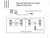
Optional Multi-Room Control Adapter Connection REAR SPEAKERS REMOTE CONTROL REMOTE RIGHT LEFT an 80 IN OUT HARMAN KARDON HE1000 REMOTE IR SENSOR 0 1 SPKR LEFT :ENEvfmari 00 000 ouou RECEIVER 0 1 SPKR RIGHT MAIN ROOM 0 2 SPKR LEFT HE1000 0 2 SPKR RIGHT REMOTE ROOM =oca= dd b ct5 as REMOTE COMMANDER 10
Optional Multi-Room Control Adapter Connection REAR SPEAKERS REMOTE CONTROL REMOTE RIGHT LEFT an 80 IN OUT HARMAN KARDON HE1000 REMOTE IR SENSOR 0 1 SPKR LEFT :ENEvfmari 00 000 ouou RECEIVER 0 1 SPKR RIGHT MAIN ROOM 0 2 SPKR LEFT HE1000 0 2 SPKR RIGHT REMOTE ROOM =oca= dd b ct5 as REMOTE COMMANDER 10
Owners Manual
Page 12
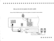
...;•• When you drive the front speakers with another amplifier (Remove PRE-OUT/MAIN IN jumpers when the front speakers are connected to external amplifier.) CENTER SPEAKER 11 FRONT CENTER REAR PRE OUT MAIN IN PRE OUT PRECUT LEFT O 0** RIGHT REAR SPEAKERS W]l RIGHT LET LINE-IN CENTER' SPEAKERS SO -SUBWOOFERi OUT 0 LE, 0 C) RIGHT RIGHT O e LEFT C) USE 8 OHM MIN SPEAKERS 0 0 RIGHT 0 0 LEFT FRONT SPEAKERS harman/kardon FRONT (left) FRONT (right) • •111...
...;•• When you drive the front speakers with another amplifier (Remove PRE-OUT/MAIN IN jumpers when the front speakers are connected to external amplifier.) CENTER SPEAKER 11 FRONT CENTER REAR PRE OUT MAIN IN PRE OUT PRECUT LEFT O 0** RIGHT REAR SPEAKERS W]l RIGHT LET LINE-IN CENTER' SPEAKERS SO -SUBWOOFERi OUT 0 LE, 0 C) RIGHT RIGHT O e LEFT C) USE 8 OHM MIN SPEAKERS 0 0 RIGHT 0 0 LEFT FRONT SPEAKERS harman/kardon FRONT (left) FRONT (right) • •111...

Owners Manual
Page 13
JUMPER PLUG CENTER SPEAKER 0 FRONT SPEAKER F ONT CENTER REAR PRECUT MAIN IN MEW. N• • IN II IN • • II IN When you drive the rear speakers with another amplifier. PRE OUT ,o, EAR SPEAKERS 110) I LINE-IN CETTER SPEAKERS SO S (BWOOFERi OUT LEFT G HT 0 USE 0 OHM MIN SPEAKERS e RIGHT Q Q LEFT e FRONT SPEAKERS harman/kardon REAR (left) REAR (right)
JUMPER PLUG CENTER SPEAKER 0 FRONT SPEAKER F ONT CENTER REAR PRECUT MAIN IN MEW. N• • IN II IN • • II IN When you drive the rear speakers with another amplifier. PRE OUT ,o, EAR SPEAKERS 110) I LINE-IN CETTER SPEAKERS SO S (BWOOFERi OUT LEFT G HT 0 USE 0 OHM MIN SPEAKERS e RIGHT Q Q LEFT e FRONT SPEAKERS harman/kardon REAR (left) REAR (right)

Owners Manual
Page 14
... sound are essential parts of cinematic presentations. DOLBY 3 STEREO Combining the front and rear signals so that of ordinary stereo regeneration. - This position provides excellent results when watching television programs, video software, video discs or video tapes of stereo television broadcasts encoded with the Dolby Surround mode (carrying the (dolby stereo) or (dolby surround) trademark*). HALL Hall mode works best for recorded concerts and other music programs. In this mode if you use a small center speaker. Dolby Stereo...
... sound are essential parts of cinematic presentations. DOLBY 3 STEREO Combining the front and rear signals so that of ordinary stereo regeneration. - This position provides excellent results when watching television programs, video software, video discs or video tapes of stereo television broadcasts encoded with the Dolby Surround mode (carrying the (dolby stereo) or (dolby surround) trademark*). HALL Hall mode works best for recorded concerts and other music programs. In this mode if you use a small center speaker. Dolby Stereo...

Owners Manual
Page 15
... output from the front (L and R) speakers 3 STEREO mode Select this mode when you play back a Dolby surround program source without using a center speaker. The sound of the rear channel is output from the front (L and R) speakers. 14 • • • a FRONT (left) CENTER FRONT (right) FRONT (left) FRONT (right) FRONT (left) CENTER CiIl FRONT (right) REAR (left) O REAR (right) REAR (left) REAR (right) WIDE mode Select this mode if you use a medium to big center speaker PHANTOM mode Select this mode when you play back a Dolby surround program source...
... output from the front (L and R) speakers 3 STEREO mode Select this mode when you play back a Dolby surround program source without using a center speaker. The sound of the rear channel is output from the front (L and R) speakers. 14 • • • a FRONT (left) CENTER FRONT (right) FRONT (left) FRONT (right) FRONT (left) CENTER CiIl FRONT (right) REAR (left) O REAR (right) REAR (left) REAR (right) WIDE mode Select this mode if you use a medium to big center speaker PHANTOM mode Select this mode when you play back a Dolby surround program source...
Owners Manual
Page 16
...; The overdrive protection circuit automatically turns off the power if it is not the one number. Tuning will blink for tuning. Press the TUNING button (DOWN or UP) to recording mode. 5. Set cassette deck 2 to tune. Press the MEMORY button and press the desired preset station button while the memory indicator blinks (it intermittently until the desired frequency is weak. C. Select the input function of the receiver are strong...
...; The overdrive protection circuit automatically turns off the power if it is not the one number. Tuning will blink for tuning. Press the TUNING button (DOWN or UP) to recording mode. 5. Set cassette deck 2 to tune. Press the MEMORY button and press the desired preset station button while the memory indicator blinks (it intermittently until the desired frequency is weak. C. Select the input function of the receiver are strong...
Owners Manual
Page 17
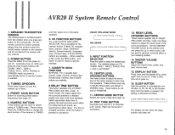
... infrared beam is used for scanning preset station frequencies (see page 14). 12. PRESET SCAN BUTTON Button for preset tuning in DOLBY PRO-LOGIC and DOLBY 3 STEREO mode. When selecting a disc, press the DISC button. Select appropriate delay time to select the desired input function. SLEEP BUTTON Sets the receiver to TUNER and then select one of the surround speakers. For the remote controls to that of the front speakers. In these buttons to adjust the sound level of the center speaker to function properly...
... infrared beam is used for scanning preset station frequencies (see page 14). 12. PRESET SCAN BUTTON Button for preset tuning in DOLBY PRO-LOGIC and DOLBY 3 STEREO mode. When selecting a disc, press the DISC button. Select appropriate delay time to select the desired input function. SLEEP BUTTON Sets the receiver to TUNER and then select one of the surround speakers. For the remote controls to that of the front speakers. In these buttons to adjust the sound level of the center speaker to function properly...

Owners Manual
Page 18
MUTE BUTTON Press this button to restore the same listening level as the power source for a long time. The volume indicator blinks. BATTERY COMPARTMENT This battery case is correct. harman/kardon O0 0 0 0 O0 0 0 0 (MIMNkardon A1170 CD, 0 :68689_ o 9 Q 8m -0-0-0 O 0 O 3.Ste 3a,--r*v3° 0000 00000 1=1. 7=.1=1 00 1±ff1 . Press again to silence the speakers temporarily. To remove the cover, press it down with your...
MUTE BUTTON Press this button to restore the same listening level as the power source for a long time. The volume indicator blinks. BATTERY COMPARTMENT This battery case is correct. harman/kardon O0 0 0 0 O0 0 0 0 (MIMNkardon A1170 CD, 0 :68689_ o 9 Q 8m -0-0-0 O 0 O 3.Ste 3a,--r*v3° 0000 00000 1=1. 7=.1=1 00 1±ff1 . Press again to silence the speakers temporarily. To remove the cover, press it down with your...
Owners Manual
Page 19
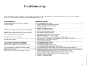
... sound is heard Dolby Surround does not work on receiver. • Cable from turntable is away from power cords and speaker cables. • Turntable is used. • Ground wire from turntable has been connected to operating errors. Stations cannot be preset. So if you have a problem, first check this list for trouble-free operation: most problems users encounter are not defective: check/replace speaker or phono cables. • The signal source is operating and providing proper signal output to...
... sound is heard Dolby Surround does not work on receiver. • Cable from turntable is away from power cords and speaker cables. • Turntable is used. • Ground wire from turntable has been connected to operating errors. Stations cannot be preset. So if you have a problem, first check this list for trouble-free operation: most problems users encounter are not defective: check/replace speaker or phono cables. • The signal source is operating and providing proper signal output to...

Owners Manual
Page 20
Specifications Stereo Mode Continuous Average Power (FTC) 60 Watts from 20Hz-20kHz: Five Channel Surround Mode Continuous average power per channel (FTC) Front L&R channels 50 Watts from 20Hz-20kHz: Center channel 50 Watts at 1kHz: Rear channels 20 Watts at 1kHz: Amplifier Section High-Instantaneous Current Capability (HCC): Negative Feedback: Frequency Response @1W (+0/-3dB): Slew Rate: Rise Time: Transient Intermodulation Distortion (TIM): Preamplifier Section Signal-to-Noise Ratio (ref. 1 Volt, A-Wtd) Phono (MM): CD: Video: Input Sensitivity/Impedance Phono (MM): Video, CD, Tape: @
Specifications Stereo Mode Continuous Average Power (FTC) 60 Watts from 20Hz-20kHz: Five Channel Surround Mode Continuous average power per channel (FTC) Front L&R channels 50 Watts from 20Hz-20kHz: Center channel 50 Watts at 1kHz: Rear channels 20 Watts at 1kHz: Amplifier Section High-Instantaneous Current Capability (HCC): Negative Feedback: Frequency Response @1W (+0/-3dB): Slew Rate: Rise Time: Transient Intermodulation Distortion (TIM): Preamplifier Section Signal-to-Noise Ratio (ref. 1 Volt, A-Wtd) Phono (MM): CD: Video: Input Sensitivity/Impedance Phono (MM): Video, CD, Tape: @


