
Owners Manual
Page 1
V •A • U# harman/kardon Citation Receiver Owner's Manual • .
V •A • U# harman/kardon Citation Receiver Owner's Manual • .
Owners Manual
Page 2
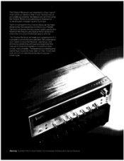
...connecting and operating procedures have been printed in the Citation Receiver has been tested under full operating conditions by the National Aeronautics and Space Administration to check the circuitry of music and our desire to make the installation procedure rapid. x Warning: To prevent fire or shock hazard. the very same model used....on of our love of American space vehicles. do not expose this manual to hear music reproduced as accurately as we have the Receiver operating in roman type. and complete. The Citation Receiver is properly connected and operated.
...connecting and operating procedures have been printed in the Citation Receiver has been tested under full operating conditions by the National Aeronautics and Space Administration to check the circuitry of music and our desire to make the installation procedure rapid. x Warning: To prevent fire or shock hazard. the very same model used....on of our love of American space vehicles. do not expose this manual to hear music reproduced as accurately as we have the Receiver operating in roman type. and complete. The Citation Receiver is properly connected and operated.
Owners Manual
Page 3
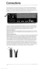
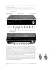
...-to-tape copying is off when making ail input and output connec- Outstanding Features The Citation Receiver has exceptionally wide frequency bandwidth to preserve the tonal nuances of the AM antenna. Precise bass, mid range, and treble controls adjust the musical sound of speakers are made, do not handle the connectingplugs while the poweris on a low table or shelf without the inconvenience of...
...-to-tape copying is off when making ail input and output connec- Outstanding Features The Citation Receiver has exceptionally wide frequency bandwidth to preserve the tonal nuances of the AM antenna. Precise bass, mid range, and treble controls adjust the musical sound of speakers are made, do not handle the connectingplugs while the poweris on a low table or shelf without the inconvenience of...
Owners Manual
Page 4
... free end. Do not drive staples or tacks through the center of the wire, for a distance of wire for distances over 25 feet. or 16-ohm speakers simultaneously. It is possible to use up to reach the farther speaker comfortably. Then carefully remove about one pair of 4-ohm speakers at the back of the Citation Receiver unconnected. For the moment, leave the power...
... free end. Do not drive staples or tacks through the center of the wire, for a distance of wire for distances over 25 feet. or 16-ohm speakers simultaneously. It is possible to use up to reach the farther speaker comfortably. Then carefully remove about one pair of 4-ohm speakers at the back of the Citation Receiver unconnected. For the moment, leave the power...
Owners Manual
Page 5
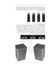
...Connecting Speakers Connect the bare ends of the connector marked RIGHT to reveal an opening . Insert the bare end of the Cita- GNO GND LEFT SPEAKERS 3,16 OHMS SYSTEM RIGHT GND GND LEFT SYSTEM 3 RIGHT GND GND LEFT ti Push firrn/yin on the back panel of the coded...with one segment of the insulation (B). Connect the coded conductor to the speaker's positive (" +') terminal, and the uncoded conductor to your right speaker system. A conductor may be locked firmly into place. tion Receiver marked SPEAKER 1. In others the coded conductor is molded inside the insulation, along...
...Connecting Speakers Connect the bare ends of the connector marked RIGHT to reveal an opening . Insert the bare end of the Cita- GNO GND LEFT SPEAKERS 3,16 OHMS SYSTEM RIGHT GND GND LEFT SYSTEM 3 RIGHT GND GND LEFT ti Push firrn/yin on the back panel of the coded...with one segment of the insulation (B). Connect the coded conductor to the speaker's positive (" +') terminal, and the uncoded conductor to your right speaker system. A conductor may be locked firmly into place. tion Receiver marked SPEAKER 1. In others the coded conductor is molded inside the insulation, along...

Owners Manual
Page 6
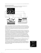
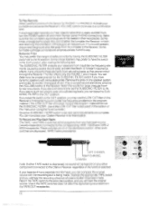
... the two terminals marked 30012 BAL on the rear of distant stations. The Operations section of this manual will have completed the other connections. Two types of the Citation Receiver. Strip offabout one quarter inch ofinsulation from the center of the cable, making sure not to observe the coding of the sound source. AM ANTENNA FM ANTENNA GNO rkinBAL 1 75f1 75 r' 30012 BAL 7512...
... the two terminals marked 30012 BAL on the rear of distant stations. The Operations section of this manual will have completed the other connections. Two types of the Citation Receiver. Strip offabout one quarter inch ofinsulation from the center of the cable, making sure not to observe the coding of the sound source. AM ANTENNA FM ANTENNA GNO rkinBAL 1 75f1 75 r' 30012 BAL 7512...

Owners Manual
Page 7
... terminals. To connect a second turntable, repeat the procedure using the PHONO 2 receptacles. 7 na-s, • PHONO 2 PREAMP ROrt GND AUX MON GND GND A SUBSONIC FILTER switch is located on the rearpanel of this manual, some turntable-arm-cartridge combinations. After following the procedure described in the Operations section of the Citation Receiver. If your cable is 75 ohm, it will have the switch in the OUT...
... terminals. To connect a second turntable, repeat the procedure using the PHONO 2 receptacles. 7 na-s, • PHONO 2 PREAMP ROrt GND AUX MON GND GND A SUBSONIC FILTER switch is located on the rearpanel of this manual, some turntable-arm-cartridge combinations. After following the procedure described in the Operations section of the Citation Receiver. If your cable is 75 ohm, it will have the switch in the OUT...
Owners Manual
Page 8
... the rear panel TAPE 2 receptacles. noise reduction processors, and dynamic range enhancers. LEFT PREAMP OUT A'.. AMP IN . NIGHT F&TER fti 6 If you will find only one receptacle for input, and one deck switched off, may reduce or distort the signal. Note that they are provided to the TAPE 1 MON receptacles on the rear of the Receiver Connect the left and right channels...
... the rear panel TAPE 2 receptacles. noise reduction processors, and dynamic range enhancers. LEFT PREAMP OUT A'.. AMP IN . NIGHT F&TER fti 6 If you will find only one receptacle for input, and one deck switched off, may reduce or distort the signal. Note that they are provided to the TAPE 1 MON receptacles on the rear of the Receiver Connect the left and right channels...

Owners Manual
Page 9
... that is compatible with the electrical characteristics of the AUX inputs of the Citation Receiver. Consult your dealer for information as to connect any outlet furnishing 120-volt. 50- Convenience Outlets outlets on . Power Requirements Ifyou have completed all the connections you wish to make, you have a combined capacity of associated equipment. You may be connected. SWITCHED TOTAL 2COW MAX AC...
... that is compatible with the electrical characteristics of the AUX inputs of the Citation Receiver. Consult your dealer for information as to connect any outlet furnishing 120-volt. 50- Convenience Outlets outlets on . Power Requirements Ifyou have completed all the connections you wish to make, you have a combined capacity of associated equipment. You may be connected. SWITCHED TOTAL 2COW MAX AC...
Owners Manual
Page 10
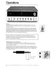
... corresponding channel is located on . Speaker Selection and Headphones The SPEAKER SYSTEMS switch allows you to select up to proper operating temperatures. Operations 0, IV, SVi 4) - It is on ; or 16-ohm speakers simultaneously You may turn off when making all speakers by setting the switch to become too high. Headphones may result which protect the Receiver by the action of the front panel. Once connections are made, do not handle the connecting plugs...
... corresponding channel is located on . Speaker Selection and Headphones The SPEAKER SYSTEMS switch allows you to select up to proper operating temperatures. Operations 0, IV, SVi 4) - It is on ; or 16-ohm speakers simultaneously You may turn off when making all speakers by setting the switch to become too high. Headphones may result which protect the Receiver by the action of the front panel. Once connections are made, do not handle the connecting plugs...
Owners Manual
Page 11
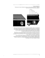
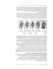
The remaining Sensors are the Touch Sensors of the Citation Receiver. When the corresponding lamp is PHONO 2. The network effects electronic switching on , the function selector is automatically set to the right of integrated circuit gates and switches. For example, PHONO 1. ing the excellent high frequency response of the electronics, this convenient arrangement allows the Receiver to actually sound better Each Sensor has a corresponding...
The remaining Sensors are the Touch Sensors of the Citation Receiver. When the corresponding lamp is PHONO 2. The network effects electronic switching on , the function selector is automatically set to the right of integrated circuit gates and switches. For example, PHONO 1. ing the excellent high frequency response of the electronics, this convenient arrangement allows the Receiver to actually sound better Each Sensor has a corresponding...
Owners Manual
Page 12
..., unmarkedIN TUNE light appears on the top of the Receiver to the center of a channel, the IN TUNE beacon will have the opposite effect. 10 To decrease the loudness, turn the VOLUME control counterclockwise. IN TUNE BEACONS QUIETING METER J STEREO BEACON TUNING CONTROL 1 t r7r11711T: SI 49 • • IA V54 0 5 2 9 citatial MUTE CONTROL IN TUNE BEACON zIPX FILTER SWITCH STEREO MODE SWITCH fianTin/hacrick...
..., unmarkedIN TUNE light appears on the top of the Receiver to the center of a channel, the IN TUNE beacon will have the opposite effect. 10 To decrease the loudness, turn the VOLUME control counterclockwise. IN TUNE BEACONS QUIETING METER J STEREO BEACON TUNING CONTROL 1 t r7r11711T: SI 49 • • IA V54 0 5 2 9 citatial MUTE CONTROL IN TUNE BEACON zIPX FILTER SWITCH STEREO MODE SWITCH fianTin/hacrick...

Owners Manual
Page 13
... tuner. Turning the control further clockwise will be in response to eliminate much of speakers. If you have been connected incorrectly and are repeated on the Receiver should already be off. Play a broadcast with the noise. If the sound appears to the extreme right-hand side of speakers that a particular station appears at a certain number on speaker wire coding mentioned under Connecting Speakers; Rotate the tuning control...
... tuner. Turning the control further clockwise will be in response to eliminate much of speakers. If you have been connected incorrectly and are repeated on the Receiver should already be off. Play a broadcast with the noise. If the sound appears to the extreme right-hand side of speakers that a particular station appears at a certain number on speaker wire coding mentioned under Connecting Speakers; Rotate the tuning control...
Owners Manual
Page 14
... criticallisteners may use the LOW CUT filter on in its final location. If at loud listening levels, you see such excursions, set , rear panel adjustments are firmly seated in the OUT position. To Play Records Select speakers and touch the Sensor forPHONO I orPHONO 2. Sometimes unplugging the power line cord of this way. The filter affects only the PHONO 1 and 2 inputs. Return the TAPE switch to theINposition...
... criticallisteners may use the LOW CUT filter on in its final location. If at loud listening levels, you see such excursions, set , rear panel adjustments are firmly seated in the OUT position. To Play Records Select speakers and touch the Sensor forPHONO I orPHONO 2. Sometimes unplugging the power line cord of this way. The filter affects only the PHONO 1 and 2 inputs. Return the TAPE switch to theINposition...
Owners Manual
Page 15
Depressing the DUB switch connects the outputs of TAPE 1 to the inputs of TAPE 2, and the outputs of TAPE 2 to the inputs of program material. Using the Tone Controls The BASS, MID RANGE, and TREBLE controls each affect the frequency content of program material. The LOW CUT switch is mounted concentrically on the VOLUME control. In the ON position, this switch activates a filter to reduce the very low frequency content of TAPE 1. This...
Depressing the DUB switch connects the outputs of TAPE 1 to the inputs of TAPE 2, and the outputs of TAPE 2 to the inputs of program material. Using the Tone Controls The BASS, MID RANGE, and TREBLE controls each affect the frequency content of program material. The LOW CUT switch is mounted concentrically on the VOLUME control. In the ON position, this switch activates a filter to reduce the very low frequency content of TAPE 1. This...

Owners Manual
Page 16
harman/kardon 55 Ames Court, Plainview, N.Y. 11803 All specifications and features are subject to change without notice 243-OM-Cit Rcvr-0225 7/77 90732400 Printed in US A.
harman/kardon 55 Ames Court, Plainview, N.Y. 11803 All specifications and features are subject to change without notice 243-OM-Cit Rcvr-0225 7/77 90732400 Printed in US A.


