
Owners Manual
Page 2
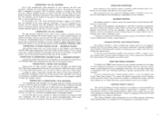
... or slots as low down and as a heat dissipating device for concern. The rear panel surface of your unit. The Harman-Kardon warranty i s not valid unless we will pay vast dividends in material and workmanship under normal use and service, and in accordance with instructions furnished by a brief note describing the exact nature of your new receiver. If this...
... or slots as low down and as a heat dissipating device for concern. The rear panel surface of your unit. The Harman-Kardon warranty i s not valid unless we will pay vast dividends in material and workmanship under normal use and service, and in accordance with instructions furnished by a brief note describing the exact nature of your new receiver. If this...
Owners Manual
Page 3
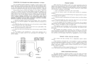
... SWITCHES Your receiver has been provided with 1 set of the room and should be referred to as Channel A.) 2. If you desire to listen to stereo-headphone alone, the speakers (either one speaker i s used i n any speaker which does not contain audio output transformers. CONNECTING THE SPEAKERS FOR STEREO OPERATION ( 1 SYSTEM) Your two speakers should appear to come from approximately the center area between the two speakers when the Function switch i s in a manner to work...
... SWITCHES Your receiver has been provided with 1 set of the room and should be referred to as Channel A.) 2. If you desire to listen to stereo-headphone alone, the speakers (either one speaker i s used i n any speaker which does not contain audio output transformers. CONNECTING THE SPEAKERS FOR STEREO OPERATION ( 1 SYSTEM) Your two speakers should appear to come from approximately the center area between the two speakers when the Function switch i s in a manner to work...
Owners Manual
Page 4
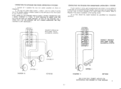
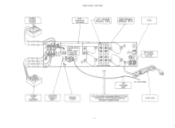
... 1 and 2 or system 2 by the use of the speaker selector switches located on the left side of the front panel of the loading resistor. Refer to the output stage o f he receiver. Connect all 4 speakers for your Nocturne receiver. CONNECTING THE SPEAKERS FOR STEREO OPERATION (2 SYSTEMS) 1. AVOID ACCIDENTAL SHORTS DIAGRAM B SYSTEM 2 SYSTEM I CONNECT SPEAKER WlTH CARE- NOTE: WHEN ALL THE SPEAKERS USED I N YOUR 2 SYSTEM CONNECTION ARE 4 OHMS, CONNECT A 2 OHM, 10 WATT RESISTOR IN SERIES...
... 1 and 2 or system 2 by the use of the speaker selector switches located on the left side of the front panel of the loading resistor. Refer to the output stage o f he receiver. Connect all 4 speakers for your Nocturne receiver. CONNECTING THE SPEAKERS FOR STEREO OPERATION (2 SYSTEMS) 1. AVOID ACCIDENTAL SHORTS DIAGRAM B SYSTEM 2 SYSTEM I CONNECT SPEAKER WlTH CARE- NOTE: WHEN ALL THE SPEAKERS USED I N YOUR 2 SYSTEM CONNECTION ARE 4 OHMS, CONNECT A 2 OHM, 10 WATT RESISTOR IN SERIES...
Owners Manual
Page 5
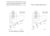
... YOUR RECEIVER DIAGRAM E Refer to the output stage of the loading resistors. CONNECTING THE SPEAKER FOR STEREOPHONIC OPERATION (SYSTEM 1) AND MONOPHONIC OPERATION (SYSTEM 2) SYSTEM I SYSTEM I DIAGRAM D 90718562 THIS IS THE ONLY CORRECT METHOD FOR CONNECTING TWO SPEAKERS MONOPHONICALLY. CONNECTING THE SPEAKERS FOR MONOPHONIC OPERATION (2 SYSTEMS) If your receiver i s to be used monophonically and stereo i s to be paralleled for proper installation of the receiver. At no time should the output...
... YOUR RECEIVER DIAGRAM E Refer to the output stage of the loading resistors. CONNECTING THE SPEAKER FOR STEREOPHONIC OPERATION (SYSTEM 1) AND MONOPHONIC OPERATION (SYSTEM 2) SYSTEM I SYSTEM I DIAGRAM D 90718562 THIS IS THE ONLY CORRECT METHOD FOR CONNECTING TWO SPEAKERS MONOPHONICALLY. CONNECTING THE SPEAKERS FOR MONOPHONIC OPERATION (2 SYSTEMS) If your receiver i s to be used monophonically and stereo i s to be paralleled for proper installation of the receiver. At no time should the output...
Owners Manual
Page 6
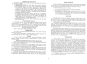
... two identical channels to adjust the volume level of any program material fed into the stereo system. This will enable you wish to hear. The tone control range i s considerable and can improve your FM reception with the two input leads, connect this receiver serves a specific useful function and i s important for the proper operation of your record player has a special ground wire emerging with an external antenna. As FM...
... two identical channels to adjust the volume level of any program material fed into the stereo system. This will enable you wish to hear. The tone control range i s considerable and can improve your FM reception with the two input leads, connect this receiver serves a specific useful function and i s important for the proper operation of your record player has a special ground wire emerging with an external antenna. As FM...

Owners Manual
Page 7
REAR PANEL TWO-HUNDRED pq RECORDER ANTENNA TERMINAL POST I I GROUND CPDNl ANTENNA I i FOR ATTACHING SPEAKERS REFER TO M E PORTION OF YOUR OWNERS M A N W I48 INCH WIRE 1 LINE CORD
REAR PANEL TWO-HUNDRED pq RECORDER ANTENNA TERMINAL POST I I GROUND CPDNl ANTENNA I i FOR ATTACHING SPEAKERS REFER TO M E PORTION OF YOUR OWNERS M A N W I48 INCH WIRE 1 LINE CORD
Owners Manual
Page 8
RECORD PLAYER RIGHT OUTPUT CABLE LEFTOUTPUTWLE LEFT INPUT CABLE RIGHT INPUT CABLE LEFT WTPLIT CABLE I RECORDER ] REAR PANEL TWO-TEN 1 & 1 1 Em SF'EAKER 1 RIW"ER "'" EFI 1 ANTENNA TERMINAL STRIP TERMINAL STRIP GROUND ANTENNA -;IRE FOR ATTACHING SPEAKERS REFER TO THE PORTION OF YOUR OWNERS MANUAL "SPEAKER CONNECTIONS" \ , LINE CORD
RECORD PLAYER RIGHT OUTPUT CABLE LEFTOUTPUTWLE LEFT INPUT CABLE RIGHT INPUT CABLE LEFT WTPLIT CABLE I RECORDER ] REAR PANEL TWO-TEN 1 & 1 1 Em SF'EAKER 1 RIW"ER "'" EFI 1 ANTENNA TERMINAL STRIP TERMINAL STRIP GROUND ANTENNA -;IRE FOR ATTACHING SPEAKERS REFER TO THE PORTION OF YOUR OWNERS MANUAL "SPEAKER CONNECTIONS" \ , LINE CORD
Owners Manual
Page 9
... any other high level equipment connected to a stereo program. PHONO MONO: Selects your record player for all FM broadcasts the function Selector Switch should be available so that i s necessary is to set , or any monitoring feature, throwing this setting and when you are not whole numbers (such as 96MC as compared to 96.3) ideally each megacycle division on the frequency scale should be...
... any other high level equipment connected to a stereo program. PHONO MONO: Selects your record player for all FM broadcasts the function Selector Switch should be available so that i s necessary is to set , or any monitoring feature, throwing this setting and when you are not whole numbers (such as 96MC as compared to 96.3) ideally each megacycle division on the frequency scale should be...

Owners Manual
Page 10
TUNING METER STEREO INDICATOR TiFRONT PANEL TWO-HUNDRED ESCUTCHEON 71 4TUNING 1-1 STEREO OFF P WES U I I I CONTOUR DEFEAT- \ 1 STEREO HEADPHONE RECEPTACLE TAPE MON ITOR SWITCH I I VOLUME CONTROL 8 POWER SWITCH \ TREBLE \ TAPE DJIP/AUX PHONOSTEREO PHONO H O W F M MONO FM STEREOMATIC BALAN~ FUNCTI? \ \ U SELECTOR SWITCHES - : .
TUNING METER STEREO INDICATOR TiFRONT PANEL TWO-HUNDRED ESCUTCHEON 71 4TUNING 1-1 STEREO OFF P WES U I I I CONTOUR DEFEAT- \ 1 STEREO HEADPHONE RECEPTACLE TAPE MON ITOR SWITCH I I VOLUME CONTROL 8 POWER SWITCH \ TREBLE \ TAPE DJIP/AUX PHONOSTEREO PHONO H O W F M MONO FM STEREOMATIC BALAN~ FUNCTI? \ \ U SELECTOR SWITCHES - : .

Owners Manual
Page 11
I I TUNING METER STEREO INDICATOR FRONT PANEL TWO-TEN PANEL ESCUTCHEON '7SCALE 7TUNING STEREO P ONES OFF CONTOUR-PUSH DEFEAT-PUU TAPE AMPAUX PHONO STEREO FY MONO STEREOMATIC HEADPHONE RECEPTACLE MONITOR SPEAKER SELECTOR SWITCHES 1 POWER SWITCH I 1 1 COBNATSRSOL I I \ CTORNETBRLOEL I 1 FUNCTION SSEWLEITCCTHOR BALANCE CONTROL
I I TUNING METER STEREO INDICATOR FRONT PANEL TWO-TEN PANEL ESCUTCHEON '7SCALE 7TUNING STEREO P ONES OFF CONTOUR-PUSH DEFEAT-PUU TAPE AMPAUX PHONO STEREO FY MONO STEREOMATIC HEADPHONE RECEPTACLE MONITOR SPEAKER SELECTOR SWITCHES 1 POWER SWITCH I 1 1 COBNATSRSOL I I \ CTORNETBRLOEL I 1 FUNCTION SSEWLEITCCTHOR BALANCE CONTROL

Owners Manual
Page 12
... used . TOTAL 32 12 MIN c TOP VlEW J FRONT PANEL ESCUTCHEON I I i' I PANEL CUTOUT FOR CUSTOM MOUNTING. 331 MAX FRONT V I E W L IMIN 2 CUSTOM INSTALLATION 1 . Your receiver is protected by running these cables too close to a strong AC field. In the event of fuse failure replace ONLY with a fuse of purchase, contact the factory for the station nearest you, please write our Customer Service Department, Harman Kardon, Inc. Plug...
... used . TOTAL 32 12 MIN c TOP VlEW J FRONT PANEL ESCUTCHEON I I i' I PANEL CUTOUT FOR CUSTOM MOUNTING. 331 MAX FRONT V I E W L IMIN 2 CUSTOM INSTALLATION 1 . Your receiver is protected by running these cables too close to a strong AC field. In the event of fuse failure replace ONLY with a fuse of purchase, contact the factory for the station nearest you, please write our Customer Service Department, Harman Kardon, Inc. Plug...
Owners Manual
Page 13
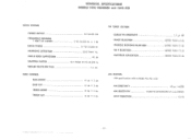
TECHNICAL SPECIFICATIONS MODELS T W O HUNDRED and T W O - TONE CONTROL BASS BOOST 1 2 db + 2 db BASS CUT 12 db * 2 db TREBLE BOOST 12 db * 2 db TREBLE CUT 12 db * 2 db FM TUNER SECTION USABLE FM SENSITIVITY 2.7 pv IHF IMAGE REJECTION BETTER THAN 45 db SPURIOUS...M SECTION (AM specifications refer to Model Two-Ten only) A M SENSITIVITY 50 pv / METER A M SELECTIVITY 10,000Hz BANDWIDTH AT 6 db POINTS AM IF REJECTION 55 db T E N AUDIO SECTION POWER OUTPUT 50 WATTS IHF FREQUENCY RESPONSE 1 WATT @ 8 OHMS 8 TO 25,000 Hz + 1 db RATED POWER 10 TO 23,000 Hz HARMONIC DISTORTION LESS THAN ...
TECHNICAL SPECIFICATIONS MODELS T W O HUNDRED and T W O - TONE CONTROL BASS BOOST 1 2 db + 2 db BASS CUT 12 db * 2 db TREBLE BOOST 12 db * 2 db TREBLE CUT 12 db * 2 db FM TUNER SECTION USABLE FM SENSITIVITY 2.7 pv IHF IMAGE REJECTION BETTER THAN 45 db SPURIOUS...M SECTION (AM specifications refer to Model Two-Ten only) A M SENSITIVITY 50 pv / METER A M SELECTIVITY 10,000Hz BANDWIDTH AT 6 db POINTS AM IF REJECTION 55 db T E N AUDIO SECTION POWER OUTPUT 50 WATTS IHF FREQUENCY RESPONSE 1 WATT @ 8 OHMS 8 TO 25,000 Hz + 1 db RATED POWER 10 TO 23,000 Hz HARMONIC DISTORTION LESS THAN ...


