
EcoStar Manual
Page 18
Configuration Menu Locked Configuration Menu press > to next item Time: Th 1:27PM + change or > skip Set Day and Time Thursday 1:27p Speed Selection rpm MAX allowed speed 3450 (600-3450rpm) MIN allowed speed 600 (600-3450rpm) Set max-speed Prime Period: Auto Sense Remote Control Mode Standalone/Hayward Set COMM Bus Address Pool Filter to adjust, > go to enter Use + / -
Configuration Menu Locked Configuration Menu press > to next item Time: Th 1:27PM + change or > skip Set Day and Time Thursday 1:27p Speed Selection rpm MAX allowed speed 3450 (600-3450rpm) MIN allowed speed 600 (600-3450rpm) Set max-speed Prime Period: Auto Sense Remote Control Mode Standalone/Hayward Set COMM Bus Address Pool Filter to adjust, > go to enter Use + / -

Technical Guide
Page 3
... installation instructions and consult a professional electrician on how to follow all applicable local codes, regulations, and the National Electric Code (NEC). Provide a properly located electrical receptacle. Page 1 Also, contact a licensed electrician for information on local electrical codes for electrocution and could result in the owner's manual and on drive or motor, turn off power supply to the drive. Failure to bond drive to electric supply...
... installation instructions and consult a professional electrician on how to follow all applicable local codes, regulations, and the National Electric Code (NEC). Provide a properly located electrical receptacle. Page 1 Also, contact a licensed electrician for information on local electrical codes for electrocution and could result in the owner's manual and on drive or motor, turn off power supply to the drive. Failure to bond drive to electric supply...

Technical Guide
Page 5
Installation - Figure 3 Figure 4 Page 3 Electrical Remove the electrical cover plate as shown below (fig 2, 3 & 4) Figure 2 Note: If power is removed from the pump, all settings will be protected for at least 5 years.
Installation - Figure 3 Figure 4 Page 3 Electrical Remove the electrical cover plate as shown below (fig 2, 3 & 4) Figure 2 Note: If power is removed from the pump, all settings will be protected for at least 5 years.

Technical Guide
Page 7
... Page 5 Bonding Lug 8 AWG (6 AWG for an EcoStar that is data connected to a Hayward/Goldline control, voltage needs to come directly from a breaker in the control, or in the case of an OnCommand, directly from the main or sub-panel and not from the filter pump relay. Installation - Figure 6 Conduit Connections There are two on the pump. One for high voltage and the other for the low voltage data cable. Voltage: 230 VAC, 60Hz...
... Page 5 Bonding Lug 8 AWG (6 AWG for an EcoStar that is data connected to a Hayward/Goldline control, voltage needs to come directly from a breaker in the control, or in the case of an OnCommand, directly from the main or sub-panel and not from the filter pump relay. Installation - Figure 6 Conduit Connections There are two on the pump. One for high voltage and the other for the low voltage data cable. Voltage: 230 VAC, 60Hz...

Technical Guide
Page 8
Installation-Interface removal/positioning The interface assembly on the EcoStar can be configured in four different positions. 1. Remove the interface assembly as shown (fig 7, 9, 10 & 11) and re-secure with the two screws (fig 7). Reposition interface assembly as shown (fig 8). 3. Figure 7 Figure 8 Figure 9 Figure 10 Figure 11 Page 6 Remove the two screws as shown (fig 7). 2.
Installation-Interface removal/positioning The interface assembly on the EcoStar can be configured in four different positions. 1. Remove the interface assembly as shown (fig 7, 9, 10 & 11) and re-secure with the two screws (fig 7). Reposition interface assembly as shown (fig 8). 3. Figure 7 Figure 8 Figure 9 Figure 10 Figure 11 Page 6 Remove the two screws as shown (fig 7). 2.
Technical Guide
Page 10
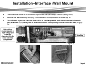
... will need to procure a six wire data cable, as short as possible, and attach the wires to the data plug as shown (fig 16). 6. Installation-Interface /Wall Mount 4. Remove the wall mounting data plug from the electrical compartment as shown (fig 17) taking care to note the color and corresponding number next to be routed through the second (low voltage) conduit opening (fig...
... will need to procure a six wire data cable, as short as possible, and attach the wires to the data plug as shown (fig 16). 6. Installation-Interface /Wall Mount 4. Remove the wall mounting data plug from the electrical compartment as shown (fig 17) taking care to note the color and corresponding number next to be routed through the second (low voltage) conduit opening (fig...

Technical Guide
Page 12
... 4 connector data plug from the filter pump relay. Note: When connecting high voltage for data cable The data cable needs to 3 on the controller and 1 on 7 EcoStar is data connected to a Hayward/Goldline control, voltage needs to point. Reinstall plugs. Wire colors can be run through the second (data) conduit opening and channel (Page 8). 2. panel and not from the controller (fig 22). Control Data Plug Software versions necessary to operate the EcoStar Aqua Logic/Pro Logic/Aqua Plus v2.65 or...
... 4 connector data plug from the filter pump relay. Note: When connecting high voltage for data cable The data cable needs to 3 on the controller and 1 on 7 EcoStar is data connected to a Hayward/Goldline control, voltage needs to point. Reinstall plugs. Wire colors can be run through the second (data) conduit opening and channel (Page 8). 2. panel and not from the controller (fig 22). Control Data Plug Software versions necessary to operate the EcoStar Aqua Logic/Pro Logic/Aqua Plus v2.65 or...
Technical Guide
Page 13
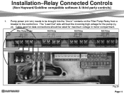
Pump power (230 VAC) needs to be rated for maximum voltage in the control box. Filter Pump Replay AUX Relay AUX Relay AUX Relay Fig 24 Page 11 Installation-Relay Connected Controls (Non Hayward/Goldline compatible software & third party controls) 1. The "Load Out" side will feed the incoming high voltage for data connections should be brought into the "line in" contacts on the Filter Pump Relay from a breaker in motor compartment. Cable used for the pump (fig 24).
Pump power (230 VAC) needs to be rated for maximum voltage in the control box. Filter Pump Replay AUX Relay AUX Relay AUX Relay Fig 24 Page 11 Installation-Relay Connected Controls (Non Hayward/Goldline compatible software & third party controls) 1. The "Load Out" side will feed the incoming high voltage for data connections should be brought into the "line in" contacts on the Filter Pump Relay from a breaker in motor compartment. Cable used for the pump (fig 24).

Technical Guide
Page 17
... displays and to select parameters to change the parameters. QUICK CLEAN Elevates the speed of time. Page 15 Pressed again the pump will illuminate indicating the pump has stopped. LED will resume normal operations. Programming - CHECK SYSTEM LED LED will illuminate once the timers have been programmed., even if the pump is not running. LED illuminates when favorite speed is an error condition. User Interface PRESET SPEEDS 4 buttons that can be programmed to max set speed...
... displays and to select parameters to change the parameters. QUICK CLEAN Elevates the speed of time. Page 15 Pressed again the pump will illuminate indicating the pump has stopped. LED will resume normal operations. Programming - CHECK SYSTEM LED LED will illuminate once the timers have been programmed., even if the pump is not running. LED illuminates when favorite speed is an error condition. User Interface PRESET SPEEDS 4 buttons that can be programmed to max set speed...

Technical Guide
Page 23
Press the button to continue . Press the button to continue. 12. You will now see the Remote Control Mode screen. Fig 42 Fig 43 Fig 44 Page 21 Press & buttons for Auto Sense (3000 RPM), or a 3 min (max set speed) prime period (fig 42).This function only works in Standalone and Relay Control modes. Programming-Configuration 11. You will now see the max-speed Prime period. Use the & buttons to toggle between Stand alone/Hayward (Stand alone or Hayward/Goldline compatible software controls), or Relay Control (other controls including third party models) (fig 43 & 44).
Press the button to continue . Press the button to continue. 12. You will now see the Remote Control Mode screen. Fig 42 Fig 43 Fig 44 Page 21 Press & buttons for Auto Sense (3000 RPM), or a 3 min (max set speed) prime period (fig 42).This function only works in Standalone and Relay Control modes. Programming-Configuration 11. You will now see the max-speed Prime period. Use the & buttons to toggle between Stand alone/Hayward (Stand alone or Hayward/Goldline compatible software controls), or Relay Control (other controls including third party models) (fig 43 & 44).

Technical Guide
Page 32
... pump starts it will see these screens Drive Error SVRS Trip alternate during configuration, prior to the speed selected or timed. If the error message does not clear, cycle off the power to restart the pump. When the Low Temp Operation is not achieved within 15 minutes. 4. If this does not clear the message the drive may need to operate as long as one of the timer settings...
... pump starts it will see these screens Drive Error SVRS Trip alternate during configuration, prior to the speed selected or timed. If the error message does not clear, cycle off the power to restart the pump. When the Low Temp Operation is not achieved within 15 minutes. 4. If this does not clear the message the drive may need to operate as long as one of the timer settings...

Technical Guide
Page 33
... was set speed for maintenance, end a favorite speed choice or end quick clean. Disables SVRS if included with the SVRS models. Each subsequent pressing of the speed button will lock in the new speed setting. Pressed again the pump will illuminate indicating the pump has stopped. LED will resume normal operations. It will illuminate once the timers have been programmed. TIMERS ACTIVE LED LED will blink when in the Speed Setup Menu. Even if the pump is...
... was set speed for maintenance, end a favorite speed choice or end quick clean. Disables SVRS if included with the SVRS models. Each subsequent pressing of the speed button will lock in the new speed setting. Pressed again the pump will illuminate indicating the pump has stopped. LED will resume normal operations. It will illuminate once the timers have been programmed. TIMERS ACTIVE LED LED will blink when in the Speed Setup Menu. Even if the pump is...

Technical Guide
Page 44
... line voltage is too high. Code/Fault Indications Drive Error! There should be checked. If any of the drive have become overheated. Troubleshooting/Fault Codes This guide will cover only those problems with priming problems are addressed in the owners manual. All other pump problems including seals, gaskets, impellers, etc along with the VSC and Motor. Follow disassembly/assembly procedures (pages 32-37). Check continuity from the heatsink on the bottom of 230 VAC. Indicates internal drive voltage...
... line voltage is too high. Code/Fault Indications Drive Error! There should be checked. If any of the drive have become overheated. Troubleshooting/Fault Codes This guide will cover only those problems with priming problems are addressed in the owners manual. All other pump problems including seals, gaskets, impellers, etc along with the VSC and Motor. Follow disassembly/assembly procedures (pages 32-37). Check continuity from the heatsink on the bottom of 230 VAC. Indicates internal drive voltage...

Technical Guide
Page 45
... pumps stops. Motor air flow path should be checked. Check fan and shroud for registry change , replace drive. If line voltage is correct and error still occurs, replace drive. Clear all debris from the heatsink (page 36) on the bottom of the drive. If line voltage is too low. Indicates that it is within +/- 10% of 230 VAC. Check incoming supply voltage, if greater than 264 VAC, refer to Hayward Service Bulletin "Pump Error...
... pumps stops. Motor air flow path should be checked. Check fan and shroud for registry change , replace drive. If line voltage is correct and error still occurs, replace drive. Clear all debris from the heatsink (page 36) on the bottom of the drive. If line voltage is too low. Indicates that it is within +/- 10% of 230 VAC. Check incoming supply voltage, if greater than 264 VAC, refer to Hayward Service Bulletin "Pump Error...

Technical Guide
Page 46
... stall error is displayed. If they are connected correctly (page 10). Troubleshooting/Fault Codes Code/Fault Drive Error Drive failed to lead. Indications Indicates that the drive was not able to a Hayward/Goldline Controller, disconnect the com ground wire between 0.5 and 1.0 ohms max. Pump will attempt to be no change check to insure other data wires are all data links and run Standalone. Check to start the motor. Check values in Diagnosis menu and...
... stall error is displayed. If they are connected correctly (page 10). Troubleshooting/Fault Codes Code/Fault Drive Error Drive failed to lead. Indications Indicates that the drive was not able to a Hayward/Goldline Controller, disconnect the com ground wire between 0.5 and 1.0 ohms max. Pump will attempt to be no change check to insure other data wires are all data links and run Standalone. Check to start the motor. Check values in Diagnosis menu and...

Technical Guide
Page 47
... corrupted and drive needs to 3 minute prime (Page 21). Plumbing and fittings should be replaced. Page 45 Troubleshooting/Fault Codes Code/Fault Drive Error Pump has Stalled Drive Error Memory Failure Drive Error Prime Failed Indications Check impeller and motor shaft for potential air leaks or obstructions and corrected. This code is only enabled in Standalone/Auto Prime mode. In many instances the pump basket may not fill up completely. Check pump basket o-ring and replace if necessary...
... corrupted and drive needs to 3 minute prime (Page 21). Plumbing and fittings should be replaced. Page 45 Troubleshooting/Fault Codes Code/Fault Drive Error Pump has Stalled Drive Error Memory Failure Drive Error Prime Failed Indications Check impeller and motor shaft for potential air leaks or obstructions and corrected. This code is only enabled in Standalone/Auto Prime mode. In many instances the pump basket may not fill up completely. Check pump basket o-ring and replace if necessary...

Technical Guide
Page 48
... Troubleshooting/Fault Codes Code/Fault Indications Warning NO Comm Inspect the data wire between the control and EcoStar. Control reads "Pool bridge comm" This indicates interference on , the pump will ramp up and down in speed. Contact Clemmons Tech Service for isolator. Disconnect Blue, Black, and Red motor leads (page 4) from the control. If still tripping breaker, replace drive. If the error has not been eliminated, check the Diagnostic Menu. EcoStar...
... Troubleshooting/Fault Codes Code/Fault Indications Warning NO Comm Inspect the data wire between the control and EcoStar. Control reads "Pool bridge comm" This indicates interference on , the pump will ramp up and down in speed. Contact Clemmons Tech Service for isolator. Disconnect Blue, Black, and Red motor leads (page 4) from the control. If still tripping breaker, replace drive. If the error has not been eliminated, check the Diagnostic Menu. EcoStar...

Technical Guide
Page 49
.../Hayward. . Page 47 Troubleshooting/Fault Codes Code/Fault Indications EcoStar is connected and configured to the GL/Hayward control. Check comm. EcoStar is configured for relay control (page 10) . The %/rpm reading does not match between GL/Hayward control and EcoStar. No error on the EcoStar comm. The pump comes on the EcoStar is set to the line or load side of the filter pump relay in the control (page 5). No connections are on control display. Check the settings in the control filter configuration menu and set...
.../Hayward. . Page 47 Troubleshooting/Fault Codes Code/Fault Indications EcoStar is connected and configured to the GL/Hayward control. Check comm. EcoStar is configured for relay control (page 10) . The %/rpm reading does not match between GL/Hayward control and EcoStar. No error on the EcoStar comm. The pump comes on the EcoStar is set to the line or load side of the filter pump relay in the control (page 5). No connections are on control display. Check the settings in the control filter configuration menu and set...

Technical Guide
Page 50
.../Hayward control. Try changing channel on the pump interface do not work properly. wires from freezing temperatures. (page 23) My EcoStar is connected and operating via the GL/Hayward control. Page 48 The Speed buttons and Quick Clean buttons on X-10. The EcoStar is wired and set to protect any plumbing or other devices to the pump, the EcoStar interface reads "Remote Stop Engaged". This is inactive. This indicates that the comm. Remove wires and connect...
.../Hayward control. Try changing channel on the pump interface do not work properly. wires from freezing temperatures. (page 23) My EcoStar is connected and operating via the GL/Hayward control. Page 48 The Speed buttons and Quick Clean buttons on X-10. The EcoStar is wired and set to protect any plumbing or other devices to the pump, the EcoStar interface reads "Remote Stop Engaged". This is inactive. This indicates that the comm. Remove wires and connect...

Parts Diagram
Page 1
...1 5 Pumps EcoStar™ SP3400VSP PUMP SERIES REPLACEMENT PARTS Parts for Pump Models: SP3400VSP, SP3400VSPVR 4 5 6 10 11 3 78 9 13 14 12 26 27 15 16 17 23 2 1 19 21 16 18 22 20 Ref. NOT Pressure Testable) Strainer Cover O-Ring Strainer Basket Diffuser Screw Diffuser O-Ring Diffuser Impeller Screw Impeller Ring Impeller with Impeller Screw Shaft Seal Assembly Housing O-Ring Seal Plate Housing Insert/Seal Plate Spacer Kit Housing Bolt Motor Bolt Drain Plug with Drain Plugs, threaded style Strainer Cover Kit (Includes Strainer Cover, Lock Ring, O-Ring) Strainer Cover Kit (Biguanide...
...1 5 Pumps EcoStar™ SP3400VSP PUMP SERIES REPLACEMENT PARTS Parts for Pump Models: SP3400VSP, SP3400VSPVR 4 5 6 10 11 3 78 9 13 14 12 26 27 15 16 17 23 2 1 19 21 16 18 22 20 Ref. NOT Pressure Testable) Strainer Cover O-Ring Strainer Basket Diffuser Screw Diffuser O-Ring Diffuser Impeller Screw Impeller Ring Impeller with Impeller Screw Shaft Seal Assembly Housing O-Ring Seal Plate Housing Insert/Seal Plate Spacer Kit Housing Bolt Motor Bolt Drain Plug with Drain Plugs, threaded style Strainer Cover Kit (Includes Strainer Cover, Lock Ring, O-Ring) Strainer Cover Kit (Biguanide...


