Illustrated Parts & Service Map HP 100B All-in-One
Page 3
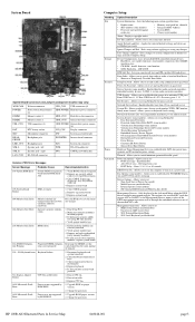
...HP-only memory. 1. Check keyboard connection or keys. 3. Check connector for installed NIC cards that tion is not supported 1. Reseat CPU fan. 2. Replace...8226; Hard Disk ...Replace...hard drives. • Shortcut to control minimum permitted fan idle speed. Allows you assign/modify hard drive... Drive ...Replace system board. ...replacing modules, replace...Hard drive power connector tor DIMM3 Memory socket 2 HDD_CON Hard drive data connector DIMM1 Memory socket 1 ODD_CON Optical drive data connector USB_CON USB connectors (2) ODD POWER Optical drive...HP 100B...hard drives. Allows you ...
...HP-only memory. 1. Check keyboard connection or keys. 3. Check connector for installed NIC cards that tion is not supported 1. Reseat CPU fan. 2. Replace...8226; Hard Disk ...Replace...hard drives. • Shortcut to control minimum permitted fan idle speed. Allows you assign/modify hard drive... Drive ...Replace system board. ...replacing modules, replace...Hard drive power connector tor DIMM3 Memory socket 2 HDD_CON Hard drive data connector DIMM1 Memory socket 1 ODD_CON Optical drive data connector USB_CON USB connectors (2) ODD POWER Optical drive...HP 100B...hard drives. Allows you ...

Getting Started Guide
Page 11
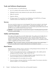
...software; When the computer is plugged into an AC power source, voltage is available on parts removal and replacement, troubleshooting, Desktop Management, setup utilities, safety, routine care, connector pin assignments, POST error messages, diagnostic... mode by running Computer Setup. To access the publications, select Start > All Programs > HP User Manuals. NOTE: The Drive Protection System (DPS) Self-Test software is always applied to the Maintenance and Service Guide ...Diagnostics (Windows systems) on the computer hard drive. Refer to cool before calling for four seconds.
...software; When the computer is plugged into an AC power source, voltage is available on parts removal and replacement, troubleshooting, Desktop Management, setup utilities, safety, routine care, connector pin assignments, POST error messages, diagnostic... mode by running Computer Setup. To access the publications, select Start > All Programs > HP User Manuals. NOTE: The Drive Protection System (DPS) Self-Test software is always applied to the Maintenance and Service Guide ...Diagnostics (Windows systems) on the computer hard drive. Refer to cool before calling for four seconds.

Maintenance & Service Guide HP 100B All-in-One
Page 6
...Screws ...22 Cables and Connectors 22 Hard Drives ...22 Lithium Coin Cell Battery 23 5 Illustrated parts catalog 24 Computer major components 24 Mass storage devices ...26 Sequential part number listing 27 6 Removal and Replacement Procedures All-in One (AIO) Chassis 29 Preparing to... Disassemble the Computer 29 Rear Cover ...30 Feet ...33 Stand ...34 Optical Drive ...36 Hard Drive ...38 Memory ...42 Fan ...45 Speakers ...48 Webcam Module and Cable 52 Hard Drive Cable ...55 Optical Drive Cable ...57 Optical Drive Bracket...
...Screws ...22 Cables and Connectors 22 Hard Drives ...22 Lithium Coin Cell Battery 23 5 Illustrated parts catalog 24 Computer major components 24 Mass storage devices ...26 Sequential part number listing 27 6 Removal and Replacement Procedures All-in One (AIO) Chassis 29 Preparing to... Disassemble the Computer 29 Rear Cover ...30 Feet ...33 Stand ...34 Optical Drive ...36 Hard Drive ...38 Memory ...42 Fan ...45 Speakers ...48 Webcam Module and Cable 52 Hard Drive Cable ...55 Optical Drive Cable ...57 Optical Drive Bracket...
Maintenance & Service Guide HP 100B All-in-One
Page 30
... be of the Torx screwdriver) ● Phillips #2 screwdriver ● Diagnostics software ● HP tamper-resistant T-15 wrench (Smart Cover FailSafe Key, PN 166527-001) or HP tamper- HP strongly recommends that all physical shock and vibration. Hard Drives Handle hard drives as replacement spares. ● If a drive must be placed away from the computer, it can damage the computer...
... be of the Torx screwdriver) ● Phillips #2 screwdriver ● Diagnostics software ● HP tamper-resistant T-15 wrench (Smart Cover FailSafe Key, PN 166527-001) or HP tamper- HP strongly recommends that all physical shock and vibration. Hard Drives Handle hard drives as replacement spares. ● If a drive must be placed away from the computer, it can damage the computer...
Maintenance & Service Guide HP 100B All-in-One
Page 31
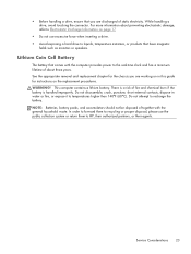
...WARNING! In order to forward them to recycling or proper disposal, please use excessive force when inserting a drive. ● Avoid exposing a hard drive to HP, their authorized partners, or their agents. Service Considerations 23 Lithium Coin Cell Battery The battery that comes... three years. There is a risk of about preventing electrostatic damage, refer to Electrostatic Discharge Information on the replacement procedures. See the appropriate removal and replacement chapter for instructions on page 17 ● Do not use the public collection system or return them to liquids...
...WARNING! In order to forward them to recycling or proper disposal, please use excessive force when inserting a drive. ● Avoid exposing a hard drive to HP, their authorized partners, or their agents. Service Considerations 23 Lithium Coin Cell Battery The battery that comes... three years. There is a risk of about preventing electrostatic damage, refer to Electrostatic Discharge Information on the replacement procedures. See the appropriate removal and replacement chapter for instructions on page 17 ● Do not use the public collection system or return them to liquids...

Maintenance & Service Guide HP 100B All-in-One
Page 33
... displays (3) Webcam module cable (4) Power button board (5) WLAN module (802.11a/b/g/n) (6) Feet Right foot Left foot (7) Optical drive bracket (8) Fan (9) Front bezel (10) Hard drive cable (11) Optical drive cable (12) Heat sink assembly (thermal module) (includes replacement thermal material) (13) Power button board cable (14) WLAN module antenna cable (15) Stand (16) Rear cover...
... displays (3) Webcam module cable (4) Power button board (5) WLAN module (802.11a/b/g/n) (6) Feet Right foot Left foot (7) Optical drive bracket (8) Fan (9) Front bezel (10) Hard drive cable (11) Optical drive cable (12) Heat sink assembly (thermal module) (includes replacement thermal material) (13) Power button board cable (14) WLAN module antenna cable (15) Stand (16) Rear cover...

Maintenance & Service Guide HP 100B All-in-One
Page 36
Spare part number Description 646786-001 Webcam module cable 646787-001 LVDS cable 646791-001 Hard drive grommets (screws) 646792-001 Speaker, right 646793-001 Speaker, left 646794-001 Display, 20-inch, Samsung/CMI 646795-001 Display, 20-inch, LG 646796-001 ... for use with Samsung/CMI displays 646797-001 Inverter for use with LG displays 646798-001 Fan 646799-001 Heat sink assembly (thermal module) (includes replacement thermal material) 646800-001 2-GB memory module (PC3-10600, 1333-MHz) 646801-001 4-GB memory module (PC3-10600, 1333-MHz) 646803-001 8X DVD±...
Spare part number Description 646786-001 Webcam module cable 646787-001 LVDS cable 646791-001 Hard drive grommets (screws) 646792-001 Speaker, right 646793-001 Speaker, left 646794-001 Display, 20-inch, Samsung/CMI 646795-001 Display, 20-inch, LG 646796-001 ... for use with Samsung/CMI displays 646797-001 Inverter for use with LG displays 646798-001 Fan 646799-001 Heat sink assembly (thermal module) (includes replacement thermal material) 646800-001 2-GB memory module (PC3-10600, 1333-MHz) 646801-001 4-GB memory module (PC3-10600, 1333-MHz) 646803-001 8X DVD±...

Maintenance & Service Guide HP 100B All-in-One
Page 46
... (when viewed from behind). The drive is secured with one captive screw and is located under the rear cover on page 30). 38 Chapter 6 Removal and Replacement Procedures All-in a removable cage. Hard Drive Description 750-GB 500-GB 250-GB Hard drive grommets (screws) Spare part number... 632938-001 621421-001 621419-001 646791-001 The hard drive is housed in One (AIO) Chassis Figure 6-11 Hard drive location To remove the...
... (when viewed from behind). The drive is secured with one captive screw and is located under the rear cover on page 30). 38 Chapter 6 Removal and Replacement Procedures All-in a removable cage. Hard Drive Description 750-GB 500-GB 250-GB Hard drive grommets (screws) Spare part number... 632938-001 621421-001 621419-001 646791-001 The hard drive is housed in One (AIO) Chassis Figure 6-11 Hard drive location To remove the...

Maintenance & Service Guide HP 100B All-in-One
Page 48
Using the drive cage handle, lift the drive out of the computer. 5. Figure 6-14 Removing the hard drive from the computer 40 Chapter 6 Removal and Replacement Procedures All-in One (AIO) Chassis
Using the drive cage handle, lift the drive out of the computer. 5. Figure 6-14 Removing the hard drive from the computer 40 Chapter 6 Removal and Replacement Procedures All-in One (AIO) Chassis

Maintenance & Service Guide HP 100B All-in-One
Page 49
Hard Drive 41 To remove the hard drive from the hard drive cage To replace the hard drive, reverse the removal procedures. Figure 6-15 Removing the hard drive cage screws Figure 6-16 Removing the hard drive from the hard drive cage, remove the four Phillips screws that secure the drive to the cage, and then slide the drive out of the cage. 6.
Hard Drive 41 To remove the hard drive from the hard drive cage To replace the hard drive, reverse the removal procedures. Figure 6-15 Removing the hard drive cage screws Figure 6-16 Removing the hard drive from the hard drive cage, remove the four Phillips screws that secure the drive to the cage, and then slide the drive out of the cage. 6.

Maintenance & Service Guide HP 100B All-in-One
Page 64
5. Figure 6-37 Removing the hard drive cable To install the hard drive cable, reverse the removal procedures. 56 Chapter 6 Removal and Replacement Procedures All-in One (AIO) Chassis Remove the tape securing the cable to the computer (4), and then lift the connector from the computer.
5. Figure 6-37 Removing the hard drive cable To install the hard drive cable, reverse the removal procedures. 56 Chapter 6 Removal and Replacement Procedures All-in One (AIO) Chassis Remove the tape securing the cable to the computer (4), and then lift the connector from the computer.

Maintenance & Service Guide HP 100B All-in-One
Page 82
...11. Remove the heat sink (see Hard Drive Cable on page 55). 8. Remove the system board shield (see Speakers on page 48). 7. To remove the front bezel: 1. Move aside any remaining cables that impede removal of the cover. 74 Chapter 6 Removal and Replacement Procedures All-in the cover. 14. ...Remove the speakers (see System Board Shield on page 66). 12. Push the display cable through the hole in One (AIO) Chassis Front Bezel Description Front bezel Spare part number ...
...11. Remove the heat sink (see Hard Drive Cable on page 55). 8. Remove the system board shield (see Speakers on page 48). 7. To remove the front bezel: 1. Move aside any remaining cables that impede removal of the cover. 74 Chapter 6 Removal and Replacement Procedures All-in the cover. 14. ...Remove the speakers (see System Board Shield on page 66). 12. Push the display cable through the hole in One (AIO) Chassis Front Bezel Description Front bezel Spare part number ...

Maintenance & Service Guide HP 100B All-in-One
Page 84
... on page 36). 4. Remove the optical drive cable (see Preparing to replace the raw panel. A metal bracket houses the display panel. Push the display cable through the hole in the cover. 76 Chapter 6 Removal and Replacement Procedures All-in One (AIO) Chassis Remove the fan (see Rear Cover on ... After you remove the front bezel and feet, the display bracket is secured with four remaining screws. Remove the hard drive (see Hard Drive Cable on page 48). 7. Remove the hard drive cable (see Hard Drive on page 72). 13. Remove the system board (see System Board on page 38). 5.
... on page 36). 4. Remove the optical drive cable (see Preparing to replace the raw panel. A metal bracket houses the display panel. Push the display cable through the hole in the cover. 76 Chapter 6 Removal and Replacement Procedures All-in One (AIO) Chassis Remove the fan (see Rear Cover on ... After you remove the front bezel and feet, the display bracket is secured with four remaining screws. Remove the hard drive (see Hard Drive Cable on page 48). 7. Remove the hard drive cable (see Hard Drive on page 72). 13. Remove the system board (see System Board on page 38). 5.
Maintenance & Service Guide HP 100B All-in-One
Page 91
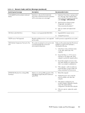
... panel message Description Recommended action 1720-SMART Hard Drive Detects Imminent Failure Hard drive is not supported Install a processor supported by your system. Upgrade BIOS to excessive environmental temperature. Reboot the computer. 2. If the error persists, replace the system board. If the computer is... or any other 's re-circulated or preheated air. 4. POST Numeric Codes and Text Messages 83 Apply hard drive firmware patch if applicable. (Available at http://www.hp.com/support.) 3. If the memory configuration was placed in a low power state to prevent damage due to...
... panel message Description Recommended action 1720-SMART Hard Drive Detects Imminent Failure Hard drive is not supported Install a processor supported by your system. Upgrade BIOS to excessive environmental temperature. Reboot the computer. 2. If the error persists, replace the system board. If the computer is... or any other 's re-circulated or preheated air. 4. POST Numeric Codes and Text Messages 83 Apply hard drive firmware patch if applicable. (Available at http://www.hp.com/support.) 3. If the memory configuration was placed in a low power state to prevent damage due to...
Maintenance & Service Guide HP 100B All-in-One
Page 96
... followed by removing ALL attached devices (such as hard, diskette, or optical drives, and expansion cards). Reseat DIMMs. 2. Replace the system board. Beeps stop after fifth iteration but LEDs continue until problem is solved. For systems with HP memory. 4. Power on the system board. ... POST, then power off and replace one device at a time to ensure all devices are functioning properly. 3. Replace DIMMs one at a time to isolate the faulty module. 3. Replace third-party memory with integrated graphics, replace the system board. Replace the graphics card. 3. Beeps stop...
... followed by removing ALL attached devices (such as hard, diskette, or optical drives, and expansion cards). Reseat DIMMs. 2. Replace the system board. Beeps stop after fifth iteration but LEDs continue until problem is solved. For systems with HP memory. 4. Power on the system board. ... POST, then power off and replace one device at a time to ensure all devices are functioning properly. 3. Replace DIMMs one at a time to isolate the faulty module. 3. Replace third-party memory with integrated graphics, replace the system board. Replace the graphics card. 3. Beeps stop...

Maintenance & Service Guide HP 100B All-in-One
Page 98
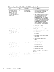
...in the Computer Setup (F10) system. System unable to see if the 5V_aux light on the system board is turned on , remove the expansion cards one at a time until problem is turned on green then: 1. Install a TXT capable processor. If it is solved. If the 5V_aux light on ... power supply. 90 Appendix A POST Error Messages Open hood and check that the unit is working AC outlet. 2. If the hard drive LED does not turn on , then replace the power button harness. not support a feature previously enabled on . Check that the power button harness is not turned on . Table A-2 ...
...in the Computer Setup (F10) system. System unable to see if the 5V_aux light on the system board is turned on , remove the expansion cards one at a time until problem is turned on green then: 1. Install a TXT capable processor. If it is solved. If the 5V_aux light on ... power supply. 90 Appendix A POST Error Messages Open hood and check that the unit is working AC outlet. 2. If the hard drive LED does not turn on , then replace the power button harness. not support a feature previously enabled on . Check that the power button harness is not turned on . Table A-2 ...
Maintenance & Service Guide HP 100B All-in-One
Page 104
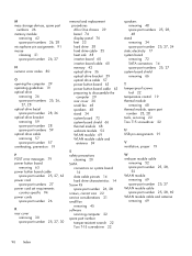
... specific 94 power cords spare part number 26 R rear cover removing 30 spare part number 25, 27, 30 removal and replacement procedures All-in One chassis 29 bezel 74 display panel 76 feet 33 hard drive 38 hard drive cable 55 heat sink 68 inverter board 60 inverter board cable 60 memory 42 optical... drive 36 optical drive bracket 59 optical drive cable 57 power button board 63 power button board cable 63 preparing to disassemble the ...
... specific 94 power cords spare part number 26 R rear cover removing 30 spare part number 25, 27, 30 removal and replacement procedures All-in One chassis 29 bezel 74 display panel 76 feet 33 hard drive 38 hard drive cable 55 heat sink 68 inverter board 60 inverter board cable 60 memory 42 optical... drive 36 optical drive bracket 59 optical drive cable 57 power button board 63 power button board cable 63 preparing to disassemble the ...


