

Maintenance and Service Guide
Page 7
... MB 32786 MB For models equipped with an Pentium 4415Y processor: 32786 MB Audio and video B&O Play dual speakers Cameras: ● Rear: MIPI-RAW 13 MP ● Front: MIPI-RAW 5 MP Wireless Intel Stone Peak 2 D1 7265 ac 2×2 + Bluetooth 4.2 M.2 non-vPro PCI-e WW with dual antenna External media cards HP Multi-Format Digital Media Card Reader Supports SD/SDHC/SDXC Push-Push insertion/removal Ports HDMI v1.4 1
... MB 32786 MB For models equipped with an Pentium 4415Y processor: 32786 MB Audio and video B&O Play dual speakers Cameras: ● Rear: MIPI-RAW 13 MP ● Front: MIPI-RAW 5 MP Wireless Intel Stone Peak 2 D1 7265 ac 2×2 + Bluetooth 4.2 M.2 non-vPro PCI-e WW with dual antenna External media cards HP Multi-Format Digital Media Card Reader Supports SD/SDHC/SDXC Push-Push insertion/removal Ports HDMI v1.4 1

Maintenance and Service Guide
Page 8
Category Description Audio-out (headphone)/Audio-in (microphone) combo jack USB Type-C power connector and charging port USB Type-C port USB 3.x ports (2) Keyboard/pointing devices Oxford Blue Island Style Keyboard Textured Touchpad Backlit Standard Notebook Keyboard Oxford Blue Island Style Keyboard Textured Touchpad Standard Notebook Keyboard Power requirements 4 Cell WHr 48 Long Life -PL Fast Charge battery 45 W nPFC USB Type-C AC adapter Security TPM 2.0 Security lock slot Operating system ChromeOS (64-bit) Serviceability End user replaceable parts: AC adapter Digital pen ...
Category Description Audio-out (headphone)/Audio-in (microphone) combo jack USB Type-C power connector and charging port USB Type-C port USB 3.x ports (2) Keyboard/pointing devices Oxford Blue Island Style Keyboard Textured Touchpad Backlit Standard Notebook Keyboard Oxford Blue Island Style Keyboard Textured Touchpad Standard Notebook Keyboard Power requirements 4 Cell WHr 48 Long Life -PL Fast Charge battery 45 W nPFC USB Type-C AC adapter Security TPM 2.0 Security lock slot Operating system ChromeOS (64-bit) Serviceability End user replaceable parts: AC adapter Digital pen ...

Maintenance and Service Guide
Page 9
... a device is using battery power. Connects a USB device that has a USB Type-C connector, supplying power to the computer and, if needed, charging the computer battery. - Connects optional powered stereo speakers, headphones, earbuds, a headset, or a television audio cable. Also connects an optional headset microphone. WARNING! Right side 3 Controls speaker volume on headphones, earbuds, or a headset. For additional safety information, refer to the jack, the computer speakers are disabled. This guide is provided in (microphone) combo jack Description Connects an AC adapter...
... a device is using battery power. Connects a USB device that has a USB Type-C connector, supplying power to the computer and, if needed, charging the computer battery. - Connects optional powered stereo speakers, headphones, earbuds, a headset, or a television audio cable. Also connects an optional headset microphone. WARNING! Right side 3 Controls speaker volume on headphones, earbuds, or a headset. For additional safety information, refer to the jack, the computer speakers are disabled. This guide is provided in (microphone) combo jack Description Connects an AC adapter...

Maintenance and Service Guide
Page 10
... (1) (2) (3) Memory card reader AC adapter and battery light USB Type-C power connector and port Description Reads optional memory cards that enable you to the computer and, if needed, charging the computer battery. - To insert a card: 1. To remove a card: ▲ Pull out the card. ● White: The AC adapter is connected and the battery is charged. ● Amber: The AC adapter is connected and the battery is charging. ● Off: The computer is firmly seated. Connects a USB device that has a USB Type-C connector, supplying power to...
... (1) (2) (3) Memory card reader AC adapter and battery light USB Type-C power connector and port Description Reads optional memory cards that enable you to the computer and, if needed, charging the computer battery. - To insert a card: 1. To remove a card: ▲ Pull out the card. ● White: The AC adapter is connected and the battery is charged. ● Amber: The AC adapter is connected and the battery is charging. ● Off: The computer is firmly seated. Connects a USB device that has a USB Type-C connector, supplying power to...
Maintenance and Service Guide
Page 11
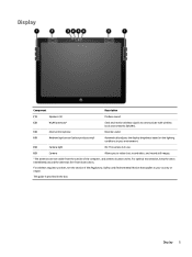
This guide is in use. (6) Camera Allows you to communicate with wireless local area networks (WLANs). (3) Internal microphone Records sound. (4) Ambient light sensor (select products only) Automatically adjusts the display brightness based on the lighting conditions in your country or region. Display 5 For optimal transmission, keep the areas immediately around the antennas free from the outside of the computer, and antenna location varies. For wireless regulatory notices, see...
This guide is in use. (6) Camera Allows you to communicate with wireless local area networks (WLANs). (3) Internal microphone Records sound. (4) Ambient light sensor (select products only) Automatically adjusts the display brightness based on the lighting conditions in your country or region. Display 5 For optimal transmission, keep the areas immediately around the antennas free from the outside of the computer, and antenna location varies. For wireless regulatory notices, see...

Maintenance and Service Guide
Page 20
... from the computer, place the subassembly (and all accompanying screws) away from the work area to prevent damage. NOTE: As you must keep in mind during disassembly and reassembly can damage plastic parts. Plastic parts CAUTION: Using excessive force during disassembly and assembly procedures. Use care when handling the plastic 14 Chapter 4 Removal and replacement. 4 Removal and replacement. procedures preliminary requirements
... from the computer, place the subassembly (and all accompanying screws) away from the work area to prevent damage. NOTE: As you must keep in mind during disassembly and reassembly can damage plastic parts. Plastic parts CAUTION: Using excessive force during disassembly and assembly procedures. Use care when handling the plastic 14 Chapter 4 Removal and replacement. 4 Removal and replacement. procedures preliminary requirements

Maintenance and Service Guide
Page 25
... an authorized service provider. CAUTION: This computer does not have user-replaceable parts. See Labels on page 9 for your computer, go to http://partsurfer.hp.com, select your country or region, and then follow the on the service tag at the bottom of your computer, including model, serial number, product key, and length of each screw size and location during removal and replacement..
... an authorized service provider. CAUTION: This computer does not have user-replaceable parts. See Labels on page 9 for your computer, go to http://partsurfer.hp.com, select your country or region, and then follow the on the service tag at the bottom of your computer, including model, serial number, product key, and length of each screw size and location during removal and replacement..

Maintenance and Service Guide
Page 26
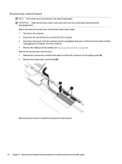
... AC adapter from the zero-insertion force connector attached to the rear(2). Remove the display panel: 1. Release the touchscreen control board cable (1) from the computer. Disconnect all external devices connected to avoid damaging the touch panel control board and display panel cables. 3. CAUTION: Use care when rotating the display panel to the computer. 3. Remove the adhesive cover (2) from the ZIF connector on the base enclosure (4). 20 Chapter 5 Removal and replacement procedures for authorized service provider parts...
... AC adapter from the zero-insertion force connector attached to the rear(2). Remove the display panel: 1. Release the touchscreen control board cable (1) from the computer. Disconnect all external devices connected to avoid damaging the touch panel control board and display panel cables. 3. CAUTION: Use care when rotating the display panel to the computer. 3. Remove the adhesive cover (2) from the ZIF connector on the base enclosure (4). 20 Chapter 5 Removal and replacement procedures for authorized service provider parts...
Maintenance and Service Guide
Page 28
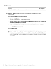
Disconnect all external devices connected to install the touchscreen control board. 22 Chapter 5 Removal and replacement procedures for authorized service provider parts IMPORTANT: Make special note of each screw and screw lock size and location during removal and replacement. Remove the display panel assembly (see Display panel assembly on the display panel (1). 2. Reverse this procedure to the computer. 3. Shut down the computer. 2. Remove the touchscreen control board(2). Release the touchscreen control board cables from the computer. 4. Disconnect the power from...
Disconnect all external devices connected to install the touchscreen control board. 22 Chapter 5 Removal and replacement procedures for authorized service provider parts IMPORTANT: Make special note of each screw and screw lock size and location during removal and replacement. Remove the display panel assembly (see Display panel assembly on the display panel (1). 2. Reverse this procedure to the computer. 3. Shut down the computer. 2. Remove the touchscreen control board(2). Release the touchscreen control board cables from the computer. 4. Disconnect the power from...

Maintenance and Service Guide
Page 33
.... 2. Detach and replace the volume button board and volume button board cable from the right speaker (1) before completely removing the speaker from the computer. 4. Disconnect all external devices connected to the base enclosure. 3. Remove the display panel (see Display panel assembly on page 20), and then remove the following components: ▲ Battery (see Battery on page 24). Component replacement procedures 27 Reverse this procedure to install the power button board. Release the speaker cable from the USB board (1). 2.
.... 2. Detach and replace the volume button board and volume button board cable from the right speaker (1) before completely removing the speaker from the computer. 4. Disconnect all external devices connected to the base enclosure. 3. Remove the display panel (see Display panel assembly on page 20), and then remove the following components: ▲ Battery (see Battery on page 24). Component replacement procedures 27 Reverse this procedure to install the power button board. Release the speaker cable from the USB board (1). 2.
Maintenance and Service Guide
Page 48
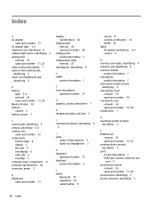
... power cord from the AC outlet and then unplugging the AC adapter from the terminals on page 24). Disconnect all external devices connected to the system board (the WLAN module tilts up). 42 Chapter 5 Removal and replacement procedures for authorized service provider parts The WLAN antenna cable labeled "2" connects to the WLAN module "Main" terminal labeled "1". Before removing the WLAN module, follow these steps: 1. Remove the display panel (see Display panel...
... power cord from the AC outlet and then unplugging the AC adapter from the terminals on page 24). Disconnect all external devices connected to the system board (the WLAN module tilts up). 42 Chapter 5 Removal and replacement procedures for authorized service provider parts The WLAN antenna cable labeled "2" connects to the WLAN module "Main" terminal labeled "1". Before removing the WLAN module, follow these steps: 1. Remove the display panel (see Display panel...
Maintenance and Service Guide
Page 56
... Bluetooth 10 regulatory 10 serial number 9 service 9 wireless certification 10 WLAN 10 lights AC adapter and battery 3, 4 camera 5 M memory card reader, identifying 4 memory card, identifying 4 memory module product description 1 microphone product description 1 microphone (audio-in) jack, identifying 3 microphone, front removal 34 spare part number 34 microphone, rear removal 36 spare part number 12, 36 model name 1 O operating system, product description 2 P POGO board removal 32 spare part number 12, 32 pointing device, product description 2 ports product description 1 USB Type-C power...
... Bluetooth 10 regulatory 10 serial number 9 service 9 wireless certification 10 WLAN 10 lights AC adapter and battery 3, 4 camera 5 M memory card reader, identifying 4 memory card, identifying 4 memory module product description 1 microphone product description 1 microphone (audio-in) jack, identifying 3 microphone, front removal 34 spare part number 34 microphone, rear removal 36 spare part number 12, 36 model name 1 O operating system, product description 2 P POGO board removal 32 spare part number 12, 32 pointing device, product description 2 ports product description 1 USB Type-C power...

Maintenance and Service Guide
Page 57
... audio 1 display panel 1 eMMC 1 external media cards 1 graphics 1 keyboard 2 memory module 1 microphone 1 operating system 2 pointing device 2 ports 1 power requirements 2 processors 1 product name 1 security 2 serviceability 2 video 1 wireless 1 product name 1 product name and number, computer 9 R regulatory information regulatory label 10 wireless certification labels 10 removal/replacement procedures 19 S screw kit spare part number 13 security, product description 2 serial number, computer 9 service labels, locating 9 serviceability, product description 2 slots memory card reader...
... audio 1 display panel 1 eMMC 1 external media cards 1 graphics 1 keyboard 2 memory module 1 microphone 1 operating system 2 pointing device 2 ports 1 power requirements 2 processors 1 product name 1 security 2 serviceability 2 video 1 wireless 1 product name 1 product name and number, computer 9 R regulatory information regulatory label 10 wireless certification labels 10 removal/replacement procedures 19 S screw kit spare part number 13 security, product description 2 serial number, computer 9 service labels, locating 9 serviceability, product description 2 slots memory card reader...

User Guide
Page 9
... using battery power. Connects a USB device that has a USB Type-C connector, supplying power to the Regulatory, Safety, and Environmental Notices. To reduce the risk of personal injury, adjust the volume before putting on the tablet. Right side 1 Controls speaker volume on headphones, earbuds, or a headset. Also connects an optional headset microphone. This guide is provided in (microphone) combo jack Description Connects an AC adapter that has a Type-C connector, such as a cell phone, camera, activity...
... using battery power. Connects a USB device that has a USB Type-C connector, supplying power to the Regulatory, Safety, and Environmental Notices. To reduce the risk of personal injury, adjust the volume before putting on the tablet. Right side 1 Controls speaker volume on headphones, earbuds, or a headset. Also connects an optional headset microphone. This guide is provided in (microphone) combo jack Description Connects an AC adapter that has a Type-C connector, such as a cell phone, camera, activity...

User Guide
Page 10
... (1) (2) (3) Memory card reader AC adapter and battery light USB Type-C power connector and port Description Reads optional memory cards that has a Type-C connector, such as a cell phone, camera, activity tracker, or smartwatch, and provides high-speed data transfer. 2 Chapter 1 Getting to know your computer and - Connects a USB device that enable you to the computer and, if needed, charging the computer battery. - Connects an AC adapter that has a USB Type-C connector, supplying power to store, manage, share, or access information. To remove a card...
... (1) (2) (3) Memory card reader AC adapter and battery light USB Type-C power connector and port Description Reads optional memory cards that has a Type-C connector, such as a cell phone, camera, activity tracker, or smartwatch, and provides high-speed data transfer. 2 Chapter 1 Getting to know your computer and - Connects a USB device that enable you to the computer and, if needed, charging the computer battery. - Connects an AC adapter that has a USB Type-C connector, supplying power to store, manage, share, or access information. To remove a card...
User Guide
Page 26
... account you sign in the Downloads folder. Follow the on your computer hard drive, including your data to change the owner of your files on your computer hard drive, including your files to see the message "Reset this Chrome device" ● You are having problems with your computer and check to an optional flash drive, SD memory card, or through Google Drive. If possible, back up...
... account you sign in the Downloads folder. Follow the on your computer hard drive, including your data to change the owner of your files on your computer hard drive, including your files to see the message "Reset this Chrome device" ● You are having problems with your computer and check to an optional flash drive, SD memory card, or through Google Drive. If possible, back up...

User Guide
Page 27
... the computer. 2. To create recovery media: 1. Before beginning the recovery process, you begin. ● A computer with Internet access. All data is an app used to recover the original operating system and software programs that were installed at the factory. Installing the Chromebook Recovery Utility The Chromebook Recovery Utility is erased from the device before you need the following: ● A flash drive or SD memory card with Internet access. This utility can be deleted. Turn on -screen instructions. Click the Launcher icon...
... the computer. 2. To create recovery media: 1. Before beginning the recovery process, you begin. ● A computer with Internet access. All data is an app used to recover the original operating system and software programs that were installed at the factory. Installing the Chromebook Recovery Utility The Chromebook Recovery Utility is erased from the device before you need the following: ● A flash drive or SD memory card with Internet access. This utility can be deleted. Turn on -screen instructions. Click the Launcher icon...

User Guide
Page 28
... close the Chromebook Recovery Utility, and then remove the flash drive or SD memory card. In the apps window, click Recovery. 3. After the recovery media is complete" message displays, remove the recovery media. Use the steps in this section to erase the recovery media using a formatting tool provided by your computer after the verification step is complete, perform the initial setup process. Click the Settings icon, and then click Erase recovery media. 4. Setting up your operating system...
... close the Chromebook Recovery Utility, and then remove the flash drive or SD memory card. In the apps window, click Recovery. 3. After the recovery media is complete" message displays, remove the recovery media. Use the steps in this section to erase the recovery media using a formatting tool provided by your computer after the verification step is complete, perform the initial setup process. Click the Settings icon, and then click Erase recovery media. 4. Setting up your operating system...
User Guide
Page 40
...8 connecting 11 keyboard connector, identifying 6 keys, esc 8 L labels Bluetooth 7 regulatory 7 serial number 6 service 6 wireless certification 7 WLAN 7 lights AC adapter and battery 1, 2 camera 3 lock screen action key 9 M memory card reader, identifying 2 memory card, identifying 2 microphone (audio-in) jack, identifying 1 mute action key 9 N next window action key 9 O operating environment 23 P ports USB Type-C power connector and port 2 power button, identifying 5 power connector, identifying 1 printing 17 product name and number, computer 6 R recovery media creating 19 erase 20 recovery...
...8 connecting 11 keyboard connector, identifying 6 keys, esc 8 L labels Bluetooth 7 regulatory 7 serial number 6 service 6 wireless certification 7 WLAN 7 lights AC adapter and battery 1, 2 camera 3 lock screen action key 9 M memory card reader, identifying 2 memory card, identifying 2 microphone (audio-in) jack, identifying 1 mute action key 9 N next window action key 9 O operating environment 23 P ports USB Type-C power connector and port 2 power button, identifying 5 power connector, identifying 1 printing 17 product name and number, computer 6 R recovery media creating 19 erase 20 recovery...
User Guide
Page 41
...reload action key 9 resetting 18 resources 21 resources, accessibility 29 W wireless certification label 7 WLAN antennas, identifying 3 WLAN device 7 WLAN label 7 S scrolling touch screen gesture 14 scrolling TouchPad gesture 14 Section 508 accessibility standards 27, 28 serial number, computer 6 service labels, locating 6 slots memory card reader 2 speaker, identifying 3 standards and legislation, accessibility 27 support 21 swiping touch screen gesture 15 system recovery Chrome operating system 19 Chromebook Recovery Utility 19 recovery media 19 T tap gestures 13 touch screen gestures one...
...reload action key 9 resetting 18 resources 21 resources, accessibility 29 W wireless certification label 7 WLAN antennas, identifying 3 WLAN device 7 WLAN label 7 S scrolling touch screen gesture 14 scrolling TouchPad gesture 14 Section 508 accessibility standards 27, 28 serial number, computer 6 service labels, locating 6 slots memory card reader 2 speaker, identifying 3 standards and legislation, accessibility 27 support 21 swiping touch screen gesture 15 system recovery Chrome operating system 19 Chromebook Recovery Utility 19 recovery media 19 T tap gestures 13 touch screen gestures one...


