
Maintenance and Service Guide
Page 1
HP Chromebook x360 11 G1 Education Edition Maintenance and Service Guide IMPORTANT! This document is intended for HP authorized service providers only.
HP Chromebook x360 11 G1 Education Edition Maintenance and Service Guide IMPORTANT! This document is intended for HP authorized service providers only.

Maintenance and Service Guide
Page 5
Table of contents 1 Product description ...1 2 External component identification ...3 Locating hardware ...3 Locating software ...3 Display ...4 TouchPad ...5 Left side ...6 Right side ...7 Bottom ...8 3 Illustrated parts catalog ...9 Locating the model number, product number, serial number, and warranty information 9 Computer major components ...10 Display assembly subcomponents ...15 Miscellaneous parts ...16 4 Removal and replacement preliminary requirements 18 Tools required ...18 Service considerations ...18 Plastic parts ...18 Cables and connectors ...18 Drive handling ...19 Grounding ...
Table of contents 1 Product description ...1 2 External component identification ...3 Locating hardware ...3 Locating software ...3 Display ...4 TouchPad ...5 Left side ...6 Right side ...7 Bottom ...8 3 Illustrated parts catalog ...9 Locating the model number, product number, serial number, and warranty information 9 Computer major components ...10 Display assembly subcomponents ...15 Miscellaneous parts ...16 4 Removal and replacement preliminary requirements 18 Tools required ...18 Service considerations ...18 Plastic parts ...18 Cables and connectors ...18 Drive handling ...19 Grounding ...

Maintenance and Service Guide
Page 7
..., noisesuppressing software Support for HD Audio Support for dual speakers Wireless Integrated wireless local area network (WLAN) options by Bluetooth® 4.2 combo card External media cards Micro-Secure Digital (SD®) media reader slot Ports ● Audio-out (headphone)/audio-in , HD, LED, BrightView (1366×7680), 220 nits, 16:9 ultra wide aspect ratio TouchScreen display assembly without digitizer, not available with stylus pen 11.6-in (microphone) combo jack ● USB 3.1 ports (2) ● USB Type-C ports (2) Keyboard/pointing devices Full-sized...
..., noisesuppressing software Support for HD Audio Support for dual speakers Wireless Integrated wireless local area network (WLAN) options by Bluetooth® 4.2 combo card External media cards Micro-Secure Digital (SD®) media reader slot Ports ● Audio-out (headphone)/audio-in , HD, LED, BrightView (1366×7680), 220 nits, 16:9 ultra wide aspect ratio TouchScreen display assembly without digitizer, not available with stylus pen 11.6-in (microphone) combo jack ● USB 3.1 ports (2) ● USB Type-C ports (2) Keyboard/pointing devices Full-sized...
Maintenance and Service Guide
Page 8
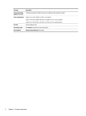
Security cable lock slot Preinstalled: Google Chrome operating system End user replaceable part: AC adapter 2 Chapter 1 Product description Category Keyboard/pointing devices (continued) Power requirements Security Operating system Serviceability Description TouchPad requirements: MultiTouch gestures enabled and Taps enabled as default Support for a 2-cell, 47-WHr, 6.15-AHr, Li-ion battery Support for 45-W AC adapter USB Type-C straight (non-PFC, 3-pin) AC adapter Support for a 1.00-m power cord with a C5 connector in 10 countries/regions.
Security cable lock slot Preinstalled: Google Chrome operating system End user replaceable part: AC adapter 2 Chapter 1 Product description Category Keyboard/pointing devices (continued) Power requirements Security Operating system Serviceability Description TouchPad requirements: MultiTouch gestures enabled and Taps enabled as default Support for a 2-cell, 47-WHr, 6.15-AHr, Li-ion battery Support for 45-W AC adapter USB Type-C straight (non-PFC, 3-pin) AC adapter Support for a 1.00-m power cord with a C5 connector in 10 countries/regions.

Maintenance and Service Guide
Page 12
... the power button during screen-lock mode turns off the computer. ● When the computer is on the computer. 6 Chapter 2 External component identification Attaches an optional security cable to the computer. Connects a USB device. NOTE: The security cable is designed to act as cell phones, laptops, tablets, and MP3 players, even when the computer is off. Left side Item Icon (1) Component Power button (2) Power light (3) Security cable slot (4) USB Type-C charging port (5) USB 3.1 port with a Type-C connector...
... the power button during screen-lock mode turns off the computer. ● When the computer is on the computer. 6 Chapter 2 External component identification Attaches an optional security cable to the computer. Connects a USB device. NOTE: The security cable is designed to act as cell phones, laptops, tablets, and MP3 players, even when the computer is off. Left side Item Icon (1) Component Power button (2) Power light (3) Security cable slot (4) USB Type-C charging port (5) USB 3.1 port with a Type-C connector...

Maintenance and Service Guide
Page 13
... of personal injury, adjust the volume before putting on the card until it is using battery power. To remove a card: ▲ Pull out the card. Right side 7 Hold the card label-side up, with HP Sleep and Charge (4) AC adapter and battery light (5) USB Type-C power connector and charging port Description Connects optional powered stereo speakers, headphones, earbuds, a headset, or a television audio cable. Right side Item Icon (1) Component Audio-out (headphone)/Audio-in (microphone) jack (2) MicroSD memory card reader (3) USB 3.1 port with connectors facing the...
... of personal injury, adjust the volume before putting on the card until it is using battery power. To remove a card: ▲ Pull out the card. Right side 7 Hold the card label-side up, with HP Sleep and Charge (4) AC adapter and battery light (5) USB Type-C power connector and charging port Description Connects optional powered stereo speakers, headphones, earbuds, a headset, or a television audio cable. Right side Item Icon (1) Component Audio-out (headphone)/Audio-in (microphone) jack (2) MicroSD memory card reader (3) USB 3.1 port with connectors facing the...

Maintenance and Service Guide
Page 24
Use care when handling the plastic parts. Improper cable placement can damage plastic parts. these cables tear easily. 18 Chapter 4 Removal and replacement preliminary requirements Cables and connectors CAUTION: When servicing the computer, be sure that they cannot be handled with extreme care; Be sure that cables are routed in such a way that cables are placed in their proper locations during removal and insertion...
Use care when handling the plastic parts. Improper cable placement can damage plastic parts. these cables tear easily. 18 Chapter 4 Removal and replacement preliminary requirements Cables and connectors CAUTION: When servicing the computer, be sure that they cannot be handled with extreme care; Be sure that cables are routed in such a way that cables are placed in their proper locations during removal and insertion...

Maintenance and Service Guide
Page 29
... user-replaceable parts. For complete and current information on -screen instructions. NOTE: HP continually improves and changes product parts. Accessing these parts can damage the computer or void the warranty. Accessing the internal part could damage the computer or void the warranty. Keyboard/top cover For use in country or region Spare part number In bon bon blue finish equipped with top cover camera and digitizer (includes keyboard cable, top cover camera cable, and digitizer cable...
... user-replaceable parts. For complete and current information on -screen instructions. NOTE: HP continually improves and changes product parts. Accessing these parts can damage the computer or void the warranty. Accessing the internal part could damage the computer or void the warranty. Keyboard/top cover For use in country or region Spare part number In bon bon blue finish equipped with top cover camera and digitizer (includes keyboard cable, top cover camera cable, and digitizer cable...

Maintenance and Service Guide
Page 31
... it on a flat surface. 2. Disconnect the power from the computer by first unplugging the power cord from the AC outlet, and then unplugging the AC adapter from the computer. Open the computer and position it down the computer.f you . 3. Shut down through the operating system. 2. Remove the following screws that secure the keyboard/top cover to the computer. 3.
... it on a flat surface. 2. Disconnect the power from the computer by first unplugging the power cord from the AC outlet, and then unplugging the AC adapter from the computer. Open the computer and position it down the computer.f you . 3. Shut down through the operating system. 2. Remove the following screws that secure the keyboard/top cover to the computer. 3.

Maintenance and Service Guide
Page 35
... TouchPad (6). Reverse this procedure to the computer. 3. Before removing the top cover camera, follow these steps: 1. Shut down through the operating system. 2. Disconnect all external devices connected to install the TouchPad. Remove the TouchPad bracket (5). 7. Remove the four Phillips PM2.0×2.9 screws (3) that secure the TouchPad to the keyboard/ top cover. 5. The top cover camera cable is off or in Hibernation, turn the computer on page 23). Remove the top cover camera: Component replacement...
... TouchPad (6). Reverse this procedure to the computer. 3. Before removing the top cover camera, follow these steps: 1. Shut down through the operating system. 2. Disconnect all external devices connected to install the TouchPad. Remove the TouchPad bracket (5). 7. Remove the four Phillips PM2.0×2.9 screws (3) that secure the TouchPad to the keyboard/ top cover. 5. The top cover camera cable is off or in Hibernation, turn the computer on page 23). Remove the top cover camera: Component replacement...

Maintenance and Service Guide
Page 40
... WLAN module to restore device functionality, and then contact technical support. Disconnect the battery cable from the system board (see Keyboard/top cover on , and then shut it down through the operating system. 2. NOTE: The WLAN antenna cable labeled "1/MAIN" connects to the WLAN module "Aux" terminal. 2. Before removing the WLAN module, follow these steps: 1. WLAN module Description Intel Dual Band Wireless-AC 7265 802.11 AC 2×2 WiFi + Bluetooth 4.2 Combo Adapter...
... WLAN module to restore device functionality, and then contact technical support. Disconnect the battery cable from the system board (see Keyboard/top cover on , and then shut it down through the operating system. 2. NOTE: The WLAN antenna cable labeled "1/MAIN" connects to the WLAN module "Aux" terminal. 2. Before removing the WLAN module, follow these steps: 1. WLAN module Description Intel Dual Band Wireless-AC 7265 802.11 AC 2×2 WiFi + Bluetooth 4.2 Combo Adapter...

Maintenance and Service Guide
Page 41
... power cord from the AC outlet, and then unplugging the AC adapter from the USB port board. 2. If you are included in Hibernation, turn the computer on page 31). Disconnect the battery cable from the slot at an angle. Component replacement procedures 35 3. Before removing the USB port board cables, follow these steps: 1. Disconnect all external devices connected to which the USB port cable is off or in the Cable Kit, spare part number...
... power cord from the AC outlet, and then unplugging the AC adapter from the USB port board. 2. If you are included in Hibernation, turn the computer on page 31). Disconnect the battery cable from the slot at an angle. Component replacement procedures 35 3. Before removing the USB port board cables, follow these steps: 1. Disconnect all external devices connected to which the USB port cable is off or in the Cable Kit, spare part number...

Maintenance and Service Guide
Page 42
... the AC adapter from the system board. 3. USB port board Description USB port board (includes USB port, volume control actuators, and hard drive activity light; Spare part number 928082-001 Before removing the USB port board, follow these steps: 1. Release the ZIF connector (2) to which the USB port cable is off or in the Cable Kit, spare part number 928086-001. Release the ZIF connector (4) to the base enclosure. 36 Chapter 5 Removal and replacement procedures Remove the keyboard/top cover (see Battery on page...
... the AC adapter from the system board. 3. USB port board Description USB port board (includes USB port, volume control actuators, and hard drive activity light; Spare part number 928082-001 Before removing the USB port board, follow these steps: 1. Release the ZIF connector (2) to which the USB port cable is off or in the Cable Kit, spare part number 928086-001. Release the ZIF connector (4) to the base enclosure. 36 Chapter 5 Removal and replacement procedures Remove the keyboard/top cover (see Battery on page...

Maintenance and Service Guide
Page 46
... the USB Type-C port cable is connected, and then disconnect the USB port cable from the system board 2. Disconnect the battery cable from the system board. 4. Release the ZIF connector (1) to remove the heat sink (see Heat sink on page 31). 6. Disconnect the camera cable (3) from the system board (see WLAN module on the replacement system board. Remove the WLAN module (see Battery on page 42) from the system board. 3. Release the camera cable from...
... the USB Type-C port cable is connected, and then disconnect the USB port cable from the system board 2. Disconnect the battery cable from the system board. 4. Release the ZIF connector (1) to remove the heat sink (see Heat sink on page 31). 6. Disconnect the camera cable (3) from the system board (see WLAN module on the replacement system board. Remove the WLAN module (see Battery on page 42) from the system board. 3. Release the camera cable from...

Maintenance and Service Guide
Page 48
... system board spare part kits. Replacement thermal material is used on , and then shut it . 42 Chapter 5 Removal and replacement procedures NOTE: The thermal material must be thoroughly cleaned from the computer. 4. Disconnect the power from the computer by first unplugging the power cord from the AC outlet, and then unplugging the AC adapter from the system board (see Keyboard/top cover...
... system board spare part kits. Replacement thermal material is used on , and then shut it . 42 Chapter 5 Removal and replacement procedures NOTE: The thermal material must be thoroughly cleaned from the computer. 4. Disconnect the power from the computer by first unplugging the power cord from the AC outlet, and then unplugging the AC adapter from the system board (see Keyboard/top cover...

Maintenance and Service Guide
Page 60
... 21 H headphone jack 7 heat sink removal 42 spare part number 14, 42 hinge removal 47 spare part number 15, 48 J jacks audio-in 7 audio-out 7 headphone 7 microphone 7 K keyboard, product description 1, 2 keyboard/top cover removal 23 spare part numbers 11, 12, 13, 23 L left-side components 6 lights AC adapter 7 battery 7 camera 4 power 6 M memory module, product description 1 microphone location 4 product description 1 microphone jack 7 MicroSD memory card reader 7 Miscellaneous Kit, spare part number 17 model name 1 mouse, spare part numbers 16 O operating system, product description...
... 21 H headphone jack 7 heat sink removal 42 spare part number 14, 42 hinge removal 47 spare part number 15, 48 J jacks audio-in 7 audio-out 7 headphone 7 microphone 7 K keyboard, product description 1, 2 keyboard/top cover removal 23 spare part numbers 11, 12, 13, 23 L left-side components 6 lights AC adapter 7 battery 7 camera 4 power 6 M memory module, product description 1 microphone location 4 product description 1 microphone jack 7 MicroSD memory card reader 7 Miscellaneous Kit, spare part number 17 model name 1 mouse, spare part numbers 16 O operating system, product description...

Maintenance and Service Guide
Page 61
... 1, 2 ports product description 1 USB 3.1 with HP Sleep and Charge 6, 7 USB Type-C charging 6 USB Type-C power connector and charging 7 power button 6 power button board removal 38 spare part number 14, 38 power button board cable removal 37 spare part number 14, 37 power cord set requirements 51 spare part numbers 16, 17 power light 6 power requirements, product description 2 processor, product description 1 product description audio 1 chipset 1 display panel 1 external media cards 1 graphics 1 keyboard 1, 2 memory module 1 microphone 1 operating system 2 pointing device 1, 2 ports 1 power...
... 1, 2 ports product description 1 USB 3.1 with HP Sleep and Charge 6, 7 USB Type-C charging 6 USB Type-C power connector and charging 7 power button 6 power button board removal 38 spare part number 14, 38 power button board cable removal 37 spare part number 14, 37 power cord set requirements 51 spare part numbers 16, 17 power light 6 power requirements, product description 2 processor, product description 1 product description audio 1 chipset 1 display panel 1 external media cards 1 graphics 1 keyboard 1, 2 memory module 1 microphone 1 operating system 2 pointing device 1, 2 ports 1 power...

User Guide
Page 7
... injury, adjust the volume before putting on the card until it is provided in (microphone) combo jack MicroSD memory card reader USB 3.1 port with connectors facing the computer. 2. To insert a card: 1. Right side 1 1 Getting to know your computer Right side Component (1) (2) (3) (4) Audio-out (headphone)/Audio-in the box. NOTE: When a device is charging. Hold the card label-side up, with HP Sleep and Charge AC adapter and battery light Description Connects optional powered stereo speakers...
... injury, adjust the volume before putting on the card until it is provided in (microphone) combo jack MicroSD memory card reader USB 3.1 port with connectors facing the computer. 2. To insert a card: 1. Right side 1 1 Getting to know your computer Right side Component (1) (2) (3) (4) Audio-out (headphone)/Audio-in the box. NOTE: When a device is charging. Hold the card label-side up, with HP Sleep and Charge AC adapter and battery light Description Connects optional powered stereo speakers...

User Guide
Page 17
... this button in full-screen mode. Volume down Decreases speaker volume incrementally as long as you hold down Displays open apps. Forward Displays the next page in your browser history. Display apps Brightness down the key. Back Displays the previous page in your browser history. Icon Key Description esc Activates certain computer functions when pressed in combination with ctrl takes a screenshot. Using the action keys 11 3 Using the action keys Using...
... this button in full-screen mode. Volume down Decreases speaker volume incrementally as long as you hold down Displays open apps. Forward Displays the next page in your browser history. Display apps Brightness down the key. Back Displays the previous page in your browser history. Icon Key Description esc Activates certain computer functions when pressed in combination with ctrl takes a screenshot. Using the action keys 11 3 Using the action keys Using...

User Guide
Page 23
...audio-out) jack 1 I internal microphones, identifying 3 J jacks audio-in ) jack, identifying 1 N Next window 11 P ports USB 3.x port 2 USB Type-C port 1 power button, identifying 2 power connector, identifying 2 Power light 2 printing 13 product name and number, computer 5 R regulatory information regulatory label 6 wireless certification labels 6 S scrolling TouchPad gesture 8, 9, 10 security cable slot, identifying 2 serial number 5 serial number, computer 5 service labels, locating 5 slots memory card reader 1 security cable 2 speakers, identifying 5 Support 14 T TouchPad and touch screen...
...audio-out) jack 1 I internal microphones, identifying 3 J jacks audio-in ) jack, identifying 1 N Next window 11 P ports USB 3.x port 2 USB Type-C port 1 power button, identifying 2 power connector, identifying 2 Power light 2 printing 13 product name and number, computer 5 R regulatory information regulatory label 6 wireless certification labels 6 S scrolling TouchPad gesture 8, 9, 10 security cable slot, identifying 2 serial number 5 serial number, computer 5 service labels, locating 5 slots memory card reader 1 security cable 2 speakers, identifying 5 Support 14 T TouchPad and touch screen...


