User Manual
Page 7
... Proactive Networking 5-9 Hardware Diagnostic Tests 5-10 Testing the Switch by Resetting It 5-10 Checking the Switch LEDs 5-10 Checking Console Messages 5-10 Testing Twisted-Pair Cabling 5-11 Testing Switch-to-Device Network Communications 5-11 Testing End-to-End Network Communications 5-11 Restoring the Factory Default Configuration 5-12 Downloading New Switch Software 5-13 HP Customer Support Services 5-14 Before Calling Support 5-14 Specifications Physical A-1 Electrical A-1 Environmental A-1 Acoustic A-2 Connectors A-2 Safety A-2 Lasers A-3 Optical Power Specifications...
... Proactive Networking 5-9 Hardware Diagnostic Tests 5-10 Testing the Switch by Resetting It 5-10 Checking the Switch LEDs 5-10 Checking Console Messages 5-10 Testing Twisted-Pair Cabling 5-11 Testing Switch-to-Device Network Communications 5-11 Testing End-to-End Network Communications 5-11 Restoring the Factory Default Configuration 5-12 Downloading New Switch Software 5-13 HP Customer Support Services 5-14 Before Calling Support 5-14 Specifications Physical A-1 Electrical A-1 Environmental A-1 Acoustic A-2 Connectors A-2 Safety A-2 Lasers A-3 Optical Power Specifications...
User Manual
Page 9
...-T (T) or SFP (S) Link 1 Mode 3 5 7 9 11 Link 13 Mode 15 17 19 21T 23T Link 21S Mode 23S Link 2 Mode 4 6 8 10 12 Link 14 Mode 16 18 20 22T 24T Link 22S Mode 24S ProCurve Switch 2900-48G (J9050A) ! Use only one (T or S) for each Port Power Fault Locator ProCurve Switch 2900-48G J9050A *Spd Mode: Link 1 Mode Off = 10 Mbps, Flash = 100 Mbps, 3 5 7 On = 1000 Mbps 9 11 Status 10G Act RPS LED Mode FDx Fan * Spd Test Usr Reset Clear Link 2 Mode 4 6 8 10...
...-T (T) or SFP (S) Link 1 Mode 3 5 7 9 11 Link 13 Mode 15 17 19 21T 23T Link 21S Mode 23S Link 2 Mode 4 6 8 10 12 Link 14 Mode 16 18 20 22T 24T Link 22S Mode 24S ProCurve Switch 2900-48G (J9050A) ! Use only one (T or S) for each Port Power Fault Locator ProCurve Switch 2900-48G J9050A *Spd Mode: Link 1 Mode Off = 10 Mbps, Flash = 100 Mbps, 3 5 7 On = 1000 Mbps 9 11 Status 10G Act RPS LED Mode FDx Fan * Spd Test Usr Reset Clear Link 2 Mode 4 6 8 10...

User Manual
Page 13
... next. Software controlled, can be flashing simultaneously. Locate function is NOT receiving power. The status LED for that component, for a prolonged time, the switch has encountered a fatal hardware failure, or has failed its self test. One of the Mode LED is controlled by the LED Mode select button, and the current setting is indicated by the LED Mode indicator LEDs near the button. Otherwise, the port may have been disabled through the port. 1-5 The default view is...
... next. Software controlled, can be flashing simultaneously. Locate function is NOT receiving power. The status LED for that component, for a prolonged time, the switch has encountered a fatal hardware failure, or has failed its self test. One of the Mode LED is controlled by the LED Mode select button, and the current setting is indicated by the LED Mode indicator LEDs near the button. Otherwise, the port may have been disabled through the port. 1-5 The default view is...
User Manual
Page 14
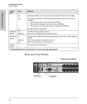
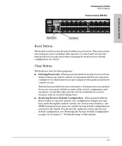
... future development. * The Flashing behavior is connected but has experienced a fault. Reset and Clear Buttons ProCurve Switch 2900-24G Power Fault Locator ProCurve Switch 2900-24G J9049A * Spd Mode: Off = 10 Mbps Flash = 100 Mbps On = 1000 Mbps Status 10G RPS LED Mode Fan Test Act FDx Spd * Usr Reset Clear Console Port to be powering the unit. RPS could be used by future software release Auxiliary Port 10/100/1000Base-T Link 1 Mode 3 5 7 9 Link 2 Mode 4 6 8 10 Reset Button Clear Button 1-6 RPS is an on...
... future development. * The Flashing behavior is connected but has experienced a fault. Reset and Clear Buttons ProCurve Switch 2900-24G Power Fault Locator ProCurve Switch 2900-24G J9049A * Spd Mode: Off = 10 Mbps Flash = 100 Mbps On = 1000 Mbps Status 10G RPS LED Mode Fan Test Act FDx Spd * Usr Reset Clear Console Port to be powering the unit. RPS could be used by future software release Auxiliary Port 10/100/1000Base-T Link 1 Mode 3 5 7 9 Link 2 Mode 4 6 8 10 Reset Button Clear Button 1-6 RPS is an on...
User Manual
Page 15
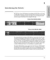
... switch console, the web browser interface, and SNMP management are concerned with the Reset button in a specific pattern, any configuration changes you have misplaced the password and need console access. Use this manual. 1-7 Introducing the Switch Introducing the Switch Front of Switch ProCurve Switch 2900-48G Power Fault Locator ProCurve Switch 2900-48G J9050A *Spd Mode: Link 1 Mode Off = 10 Mbps, Flash = 100 Mbps, 3 5 7 On = 1000 Mbps 9 11 Status 10G Act RPS LED Mode FDx Fan * Spd Test Usr Reset Clear Link 2 Mode 4 6 8 10 12 10/100/1 Link...
... switch console, the web browser interface, and SNMP management are concerned with the Reset button in a specific pattern, any configuration changes you have misplaced the password and need console access. Use this manual. 1-7 Introducing the Switch Introducing the Switch Front of Switch ProCurve Switch 2900-48G Power Fault Locator ProCurve Switch 2900-48G J9050A *Spd Mode: Link 1 Mode Off = 10 Mbps, Flash = 100 Mbps, 3 5 7 On = 1000 Mbps 9 11 Status 10G Act RPS LED Mode FDx Fan * Spd Test Usr Reset Clear Link 2 Mode 4 6 8 10 12 10/100/1 Link...
User Manual
Page 18
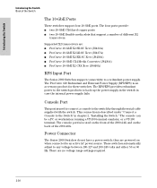
The ProCurve 620 Redundant and External Power Supply (RPS/EPS) is described under "Connect a Console to the switch by through the serial cable supplied with the switch. The RPS/EPS provides redundant power to the switch products to a redundant power supply. The four ports provide: ■ two 10-GbE CX4 fixed copper ports ■ two 10-GbE flexible media slots that support a number of the 2900-48G. This connection is...
The ProCurve 620 Redundant and External Power Supply (RPS/EPS) is described under "Connect a Console to the switch by through the serial cable supplied with the switch. The RPS/EPS provides redundant power to the switch products to a redundant power supply. The four ports provide: ■ two 10-GbE CX4 fixed copper ports ■ two 10-GbE flexible media slots that support a number of the 2900-48G. This connection is...

User Manual
Page 19
... link speed. ■ Easy management of the switch through twistedpair cables. Cross-over cables are enabled-just connect the network cables to active network devices and your switched network is connected to a ProCurve 620 RPS/EPS and receive redundant system power from common web browsers. 1-11 The pin operation of each port. ■ Four 10-GbE ports: Two fixed CX4 ports and two X2 transceiver bays which support a variety of -band switch management or for Telnet access...
... link speed. ■ Easy management of the switch through twistedpair cables. Cross-over cables are enabled-just connect the network cables to active network devices and your switched network is connected to a ProCurve 620 RPS/EPS and receive redundant system power from common web browsers. 1-11 The pin operation of each port. ■ Four 10-GbE ports: Two fixed CX4 ports and two X2 transceiver bays which support a variety of -band switch management or for Telnet access...

User Manual
Page 36
... the switch ports, when a network cable from the network devices or your patch panels to the fixed RJ-45 ports on . When S tatus ower 10G Act power is on for the switch and for the RPS LED Mode FDx ault Fan * Spd Test Usr connected device, the Link LED for the port cator Reset Clear Link 2 Mode 4 should go on the switch or to the port, the Link LED for example, an end node) is installed in chapter 5, "Troubleshooting". 2-16...
... the switch ports, when a network cable from the network devices or your patch panels to the fixed RJ-45 ports on . When S tatus ower 10G Act power is on for the switch and for the RPS LED Mode FDx ault Fan * Spd Test Usr connected device, the Link LED for the port cator Reset Clear Link 2 Mode 4 should go on the switch or to the port, the Link LED for example, an end node) is installed in chapter 5, "Troubleshooting". 2-16...
User Manual
Page 38
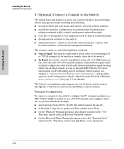
... -band console access or through the Console Port and one in troubleshooting ■ download new software to the switch ■ add passwords to control access to the switch from the console, web browser interface, and network management stations The console can be accessed through these methods: ■ Out-of-band: The switch comes with a serial cable for connecting a PC or VT-100 terminal, to be used as a console, directly to the switch. ■ In-Band: Access the console using either...
... -band console access or through the Console Port and one in troubleshooting ■ download new software to the switch ■ add passwords to control access to the switch from the console, web browser interface, and network management stations The console can be accessed through these methods: ■ Out-of-band: The switch comes with a serial cable for connecting a PC or VT-100 terminal, to be used as a console, directly to the switch. ■ In-Band: Access the console using either...
User Manual
Page 39
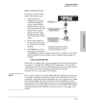
... LED Mode FDx Fan Spd * Test Usr Reset Clear Console * Spd Mode: Off = 10 Mbps Flash = 100 Mbps Link 1 Mode 3 5 On = 0100 Mbps P or t t o be used by future sof tw are compatible. Connect the PC or terminal to the switch's Console Port using a PC, start the PC terminal program. Turn on the Switch 2900-48G is on the ProCurve Web site, www.procurve.com. (See page 5-1 for your PC or terminal has a 25-pin Console cable supplied serial...
... LED Mode FDx Fan Spd * Test Usr Reset Clear Console * Spd Mode: Off = 10 Mbps Flash = 100 Mbps Link 1 Mode 3 5 On = 0100 Mbps P or t t o be used by future sof tw are compatible. Connect the PC or terminal to the switch's Console Port using a PC, start the PC terminal program. Turn on the Switch 2900-48G is on the ProCurve Web site, www.procurve.com. (See page 5-1 for your PC or terminal has a 25-pin Console cable supplied serial...
User Manual
Page 53
... remote Telnet session, through inband (networked) access, you should configure the switch with an IP address and subnet mask compatible with values you should configure a Manager password to the switch, set a Manager password, and, optionally, configure other switch management interfaces: the web browser interface and the SNMP management tool, ProCurve Manager, please see the Management and Configuration Guide, which is a guide for using the console Switch Setup screen to quickly assign an IP (Internet Protocol) address and subnet mask to control access privileges from an SNMP network...
... remote Telnet session, through inband (networked) access, you should configure the switch with an IP address and subnet mask compatible with values you should configure a Manager password to the switch, set a Manager password, and, optionally, configure other switch management interfaces: the web browser interface and the SNMP management tool, ProCurve Manager, please see the Management and Configuration Guide, which is a guide for using the console Switch Setup screen to quickly assign an IP (Internet Protocol) address and subnet mask to control access privileges from an SNMP network...

User Manual
Page 54
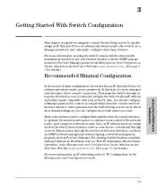
... address configuration from a DHCP or Bootp server. Getting Started With Switch Configuration 3. The following illustration shows the Setup screen with the default settings. At the prompt, enter the setup command to the switch and display the switch console command (CLI) prompt (the default display). To use a direct console connection to the switch, start a console session, and access the Switch Setup screen. 1. Using the method described in your network is configured to 16 characters. 3-2 Use the [Tab] key to select the Manager Password field and enter a manager password...
... address configuration from a DHCP or Bootp server. Getting Started With Switch Configuration 3. The following illustration shows the Setup screen with the default settings. At the prompt, enter the setup command to the switch and display the switch console command (CLI) prompt (the default display). To use a direct console connection to the switch, start a console session, and access the Switch Setup screen. 1. Using the method described in your network is configured to 16 characters. 3-2 Use the [Tab] key to select the Manager Password field and enter a manager password...

User Manual
Page 55
... Default CLI The default setting selects the command line interface for details.): Parameter Default System Name blank Optional; The options are SNTP and TimeP. Time Sync Method None Optional; Default Gateway blank Optional; IP Address xxx.xxx.xxx.xxx Recommended; Community Name public Default setting recommended. The protocol the switch uses to -1440. For more information on IP addressing, see the Management and Configuration Guide, which is on your network or the switch...
... Default CLI The default setting selects the command line interface for details.): Parameter Default System Name blank Optional; The options are SNTP and TimeP. Time Sync Method None Optional; Default Gateway blank Optional; IP Address xxx.xxx.xxx.xxx Recommended; Community Name public Default setting recommended. The protocol the switch uses to -1440. For more information on IP addressing, see the Management and Configuration Guide, which is on your network or the switch...

User Manual
Page 67
The Series 2900 Switch devices also support Trunking, which allows multiple network cables to determine the port's configuration and verify that there is not an improper or undesired configuration of any time, thus avoiding data path loops. Use the switch console to be affecting the port. A port on the ProCurve Web site, www.procurve.com. Go to the technical note "Troubleshooting LAN Performance and Intermittent Connectivity Problems", which is active at any of the switch features...
The Series 2900 Switch devices also support Trunking, which allows multiple network cables to determine the port's configuration and verify that there is not an improper or undesired configuration of any time, thus avoiding data path loops. Use the switch console to be affecting the port. A port on the ProCurve Web site, www.procurve.com. Go to the technical note "Troubleshooting LAN Performance and Intermittent Connectivity Problems", which is active at any of the switch features...

User Manual
Page 69
... your ProCurve authorized LAN dealer, or use the electronic support services from the switch and wait a few moments. Try resetting the switch by pressing the Reset button on the console screen and in . You can view the console log at that the AC power source works by selecting it to operate at least six fans and may have failed. Then reconnect the switch cooling power to operate failed. If the error indication...
... your ProCurve authorized LAN dealer, or use the electronic support services from the switch and wait a few moments. Try resetting the switch by pressing the Reset button on the console screen and in . You can view the console log at that the AC power source works by selecting it to operate at least six fans and may have failed. Then reconnect the switch cooling power to operate failed. If the error indication...

User Manual
Page 71
... switch, to the switch, use straight-through or crossover cables can use the console interface, or, if you have used because of cable for the connection. Troubleshooting Troubleshooting Diagnosing with the LEDs Tip Problem Solution ➏ The network Try the following procedures: connection is not • For the indicated port, verify both powered on and operating correctly. • Verify you have configured an IP address on the switch, use the web browser interface, or ProCurve Manager network management software...
... switch, to the switch, use straight-through or crossover cables can use the console interface, or, if you have used because of cable for the connection. Troubleshooting Troubleshooting Diagnosing with the LEDs Tip Problem Solution ➏ The network Try the following procedures: connection is not • For the indicated port, verify both powered on and operating correctly. • Verify you have configured an IP address on the switch, use the web browser interface, or ProCurve Manager network management software...
User Manual
Page 76
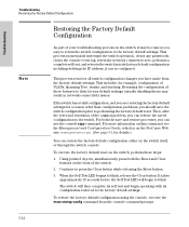
... Restoring the Factory Default Configuration As part of your troubleshooting process on the switch, perform these features to their factory default settings (usually disabling them) may become necessary to return the switch configuration to the factory default settings. To execute the factory default reset on the switch, it may result in network connectivity issues. For more information on the front of VLANs, Spanning Tree, trunks, and stacking. To restore the factory default configuration using the console, execute the erase startup-config command...
... Restoring the Factory Default Configuration As part of your troubleshooting process on the switch, perform these features to their factory default settings (usually disabling them) may become necessary to return the switch configuration to the factory default settings. To execute the factory default reset on the switch, it may result in network connectivity issues. For more information on the front of VLANs, Spanning Tree, trunks, and stacking. To restore the factory default configuration using the console, execute the erase startup-config command...

User Manual
Page 78
... the switch's status including the software (OS) version, a copy of the switch configuration, a copy of the switch Event Log, and a copy of the switch status and counters information switch console: show tech command • copy of your switch, Hewlett-Packard offers support 24 hours a day, seven days a week through the use of a number of the switch and on labels on how to use these services to get technical support. Additionally, your ProCurve authorized network...
... the switch's status including the software (OS) version, a copy of the switch configuration, a copy of the switch Event Log, and a copy of the switch status and counters information switch console: show tech command • copy of your switch, Hewlett-Packard offers support 24 hours a day, seven days a week through the use of a number of the switch and on labels on how to use these services to get technical support. Additionally, your ProCurve authorized network...
User Manual
Page 107
...basic switch configuration IP address ... 3-3 manager password ... 3-2 subnet mask ... 3-3 switch setup screen ... 3-2 basic troubleshooting tips ... 5-1 battery replacing battery ... 4-4 blinking LEDs error indications ... 5-4 Bootp automatic switch configuration ... 3-2 for direct console connection ... 2-19 cables, twisted pair category 3, 4, 5 ... B-6, B-8 HP Auto-MDIX feature ... B-2 infrastructure requirements ... 2-5 length limitations ... 2-5 required types ... 2-5 serial, for in-band access ... 2-18 buttons clear button ... 1-7 reset button ... 1-7 C cabinet mounting the switch...
...basic switch configuration IP address ... 3-3 manager password ... 3-2 subnet mask ... 3-3 switch setup screen ... 3-2 basic troubleshooting tips ... 5-1 battery replacing battery ... 4-4 blinking LEDs error indications ... 5-4 Bootp automatic switch configuration ... 3-2 for direct console connection ... 2-19 cables, twisted pair category 3, 4, 5 ... B-6, B-8 HP Auto-MDIX feature ... B-2 infrastructure requirements ... 2-5 length limitations ... 2-5 required types ... 2-5 serial, for in-band access ... 2-18 buttons clear button ... 1-7 reset button ... 1-7 C cabinet mounting the switch...
User Manual
Page 111
... safety specifications ... A-1 switch operation verifying after installation ... 2-11 Switch Setup screen configuring a subnet mask ... 3-3 configuring an IP address ... 3-3 field descriptions ... 3-3 switch setup screen ... 3-2 T telnet access to the console ... 3-5 Temp Status LED ... 2-22 terminal configuration ... 2-18 Test LED behavior during factory default reset ... 5-12 serial cable for direct console connection ... 2-19 slots for troubleshooting ... 5-1 topologies effects of improper topology ... 5-2 samples of reset button ... 1-7 troubleshooting procedure ... 5-10 RPS connections...
... safety specifications ... A-1 switch operation verifying after installation ... 2-11 Switch Setup screen configuring a subnet mask ... 3-3 configuring an IP address ... 3-3 field descriptions ... 3-3 switch setup screen ... 3-2 T telnet access to the console ... 3-5 Temp Status LED ... 2-22 terminal configuration ... 2-18 Test LED behavior during factory default reset ... 5-12 serial cable for direct console connection ... 2-19 slots for troubleshooting ... 5-1 topologies effects of improper topology ... 5-2 samples of reset button ... 1-7 troubleshooting procedure ... 5-10 RPS connections...


