User Manual
Page 6
... 2-20 Terminal Configuration 2-20 Direct Console Access 2-21 Telnet Console Access 2-21 Hot Swapping Switch Modules 2-22 Adding or Replacing Modules 2-22 Changing the Module Type 2-22 Example Network Topologies 2-23 Basic Connectivity 2-23 Legacy Connectivity 2-24 Use as an Edge Switch 2-25 Used as an Aggregation Switch 2-26 3 Getting Started With Switch Configuration Recommended Minimal Configuration 3-1 Using the Switch Setup Screen 3-2 Where to Go From Here 3-4 Using the IP Address for Remote Switch Management 3-5 Starting a Telnet Session 3-5 Starting a Web Browser Session...
... 2-20 Terminal Configuration 2-20 Direct Console Access 2-21 Telnet Console Access 2-21 Hot Swapping Switch Modules 2-22 Adding or Replacing Modules 2-22 Changing the Module Type 2-22 Example Network Topologies 2-23 Basic Connectivity 2-23 Legacy Connectivity 2-24 Use as an Edge Switch 2-25 Used as an Aggregation Switch 2-26 3 Getting Started With Switch Configuration Recommended Minimal Configuration 3-1 Using the Switch Setup Screen 3-2 Where to Go From Here 3-4 Using the IP Address for Remote Switch Management 3-5 Starting a Telnet Session 3-5 Starting a Web Browser Session...

User Manual
Page 7
... Switch Ports and Network Cables Switch Ports B-1 Twisted Pair B-1 Fiber-Optic B-1 Cables B-2 Fiber-Optic Cables B-3 Copper Cables B-4 Twisted-Pair Cable/Connector Pin-Outs B-5 Straight-Through Twisted-Pair Cable for 10 Mbps or 100 Mbps Network Connections B-7 Cable Diagram B-7 Pin Assignments B-7 Crossover Twisted-Pair Cable for 10 Mbps or 100 Mbps Network Connection B-8 Cable Diagram B-8 Pin Assignments B-8 Straight-Through Twisted-Pair Cable for 1000 Mbps Network Connections B-9 Cable Diagram B-9 Pin Assignments B-9 v Downloading New Code 4-14 HP Customer Support Services...
... Switch Ports and Network Cables Switch Ports B-1 Twisted Pair B-1 Fiber-Optic B-1 Cables B-2 Fiber-Optic Cables B-3 Copper Cables B-4 Twisted-Pair Cable/Connector Pin-Outs B-5 Straight-Through Twisted-Pair Cable for 10 Mbps or 100 Mbps Network Connections B-7 Cable Diagram B-7 Pin Assignments B-7 Crossover Twisted-Pair Cable for 10 Mbps or 100 Mbps Network Connection B-8 Cable Diagram B-8 Pin Assignments B-8 Straight-Through Twisted-Pair Cable for 1000 Mbps Network Connections B-9 Cable Diagram B-9 Pin Assignments B-9 v Downloading New Code 4-14 HP Customer Support Services...
User Manual
Page 14
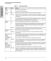
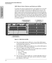
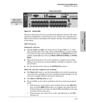
.... Switch Chassis LEDs LEDs Power (green) Fault (orange) State On Off Off Flashing1 On Self Test Off (green) On Flashing1 Status/Fan (green) On Flashing1 Status/Power On (green - The normal operational state; One or more information. A power supply is not plugged in position 1. The switch Fault LED will flash simultaneously. The Status LED for example a switch module, and the switch Fault LED will be flashing simultaneously. Introducing the ProCurve Switch 4200vl Series Introducing the ProCurve Switch 4200vl Series Front of the switch has failed...
.... Switch Chassis LEDs LEDs Power (green) Fault (orange) State On Off Off Flashing1 On Self Test Off (green) On Flashing1 Status/Fan (green) On Flashing1 Status/Power On (green - The normal operational state; One or more information. A power supply is not plugged in position 1. The switch Fault LED will flash simultaneously. The Status LED for example a switch module, and the switch Fault LED will be flashing simultaneously. Introducing the ProCurve Switch 4200vl Series Introducing the ProCurve Switch 4200vl Series Front of the switch has failed...
User Manual
Page 15
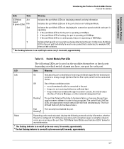
... LED Mode Act Select (3 green LEDs) FDx Spd Indicates the port Mode LEDs are occurring on /off cycle once every 1.6 seconds, approximately. 2 The fast flashing behavior is not receiving link beat or sufficient light • the port has been disabled through the switch console, the web browser interface, ProCurve Manager, or other network management tool. Indicates the port Mode LEDs are lit for each port. The switch Fault, Self Test LEDs, and appropriate module status LEDs will flash only for example CRC errors...
... LED Mode Act Select (3 green LEDs) FDx Spd Indicates the port Mode LEDs are occurring on /off cycle once every 1.6 seconds, approximately. 2 The fast flashing behavior is not receiving link beat or sufficient light • the port has been disabled through the switch console, the web browser interface, ProCurve Manager, or other network management tool. Indicates the port Mode LEDs are lit for each port. The switch Fault, Self Test LEDs, and appropriate module status LEDs will flash only for example CRC errors...
User Manual
Page 16
... the Switch 4200vl Series. After ten minutes, the Mode button setting reverts back to the next. The Mode Select button and LEDs are HP Auto MDI-X Serial No. X 5 7 9 11 Link 13 Mode 15 17 19 Spd mode: off = 10 Mbps flash = 100 Mbps on the switch chassis, and the current selection is lit, the port Mode LEDs light for each port) ProCurve Switch 4202vl J8772A Power Console Fault Link 1 Mode 3 Reset Self Test Clear Auxiliary Port Status 12AB Fan Power Modules Use vl Modules only 10/100Base-TX Ports - LED Mode...
... the Switch 4200vl Series. After ten minutes, the Mode button setting reverts back to the next. The Mode Select button and LEDs are HP Auto MDI-X Serial No. X 5 7 9 11 Link 13 Mode 15 17 19 Spd mode: off = 10 Mbps flash = 100 Mbps on the switch chassis, and the current selection is lit, the port Mode LEDs light for each port) ProCurve Switch 4202vl J8772A Power Console Fault Link 1 Mode 3 Reset Self Test Clear Auxiliary Port Status 12AB Fan Power Modules Use vl Modules only 10/100Base-TX Ports - LED Mode...
User Manual
Page 17
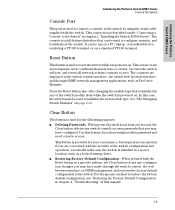
... pressed by using the serial cable supplied with the Reset button in chapter 2, "Installing the Switch 4200vl Series". For the specific method to initialize the new module type. It can be reset to restore the factory default configuration, see "Restoring the Factory Default Configuration" in the switch console interface, the switch web browser interface, and through the switch console, the web browser interface, or SNMP management, and restores the factory default configuration to the Switch" in a specific pattern, the Clear button clears any switch console access passwords that...
... pressed by using the serial cable supplied with the Reset button in chapter 2, "Installing the Switch 4200vl Series". For the specific method to initialize the new module type. It can be reset to restore the factory default configuration, see "Restoring the Factory Default Configuration" in the switch console interface, the switch web browser interface, and through the switch console, the web browser interface, or SNMP management, and restores the factory default configuration to the Switch" in a specific pattern, the Clear button clears any switch console access passwords that...
User Manual
Page 24
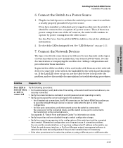
... this point, the switch is required for any empty switch power supply slot. Configuration changes can be managed using a web browser or from becoming unstable and/or falling over. ■ Ensure a cover plate is installed in a rack or cabinet should never have the HP Auto MDI-X feature, and the 10/100/1000Base-T ports on any of your twisted-pair network connections. 8. (Optional) Connect a console to enter any module or power supply slots...
... this point, the switch is required for any empty switch power supply slot. Configuration changes can be managed using a web browser or from becoming unstable and/or falling over. ■ Ensure a cover plate is installed in a rack or cabinet should never have the HP Auto MDI-X feature, and the 10/100/1000Base-T ports on any of your twisted-pair network connections. 8. (Optional) Connect a console to enter any module or power supply slots...
User Manual
Page 33
..., and the chassis LEDs go on as the port is tested. ■ For the duration of the self test, the Self Test LED stays on. The entire download, initialization, and self test process can take up to 2 minutes for a fully loaded chassis, depending on briefly, in the switch. You may see each port switch chassis LEDs ProCurve Switch 4204vl J8770A Power Console Self Test Reset Clear Auxiliary Port Status 12ABCD Fan Power Modules Spd mode: off = 10 Mbps flash = 100...
..., and the chassis LEDs go on as the port is tested. ■ For the duration of the self test, the Self Test LED stays on. The entire download, initialization, and self test process can take up to 2 minutes for a fully loaded chassis, depending on briefly, in the switch. You may see each port switch chassis LEDs ProCurve Switch 4204vl J8770A Power Console Self Test Reset Clear Auxiliary Port Status 12ABCD Fan Power Modules Spd mode: off = 10 Mbps flash = 100...
User Manual
Page 39
... port is connected to the transmit port on the types of connection problems. You can use Telnet, the web browser interface, or ProCurve Manager network management software to a Power Source 1. If you have installed a redundant power supply module into a nearby properly grounded AC power source. See "LED Behavior" on the switch, use the console interface, or, if you have installed in your Series 4200vl Switch. Re-check the LEDs during self test. Connect the Switch to determine the state and configuration of the switch port and the connected device...
... port is connected to the transmit port on the types of connection problems. You can use Telnet, the web browser interface, or ProCurve Manager network management software to a Power Source 1. If you have installed a redundant power supply module into a nearby properly grounded AC power source. See "LED Behavior" on the switch, use the console interface, or, if you have installed in your Series 4200vl Switch. Re-check the LEDs during self test. Connect the Switch to determine the state and configuration of the switch port and the connected device...
User Manual
Page 40
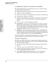
... in troubleshooting ■ Download new software to the switch ■ Add passwords and other security features to control access to the switch from a PC or UNIX station on the network, and a VT-100 terminal emulator. This method requires that comes with an IP address and subnet mask by using telnet from the console, web browser interface, and network management stations The console can be used as a console, directly to the switch using the serial cable that...
... in troubleshooting ■ Download new software to the switch ■ Add passwords and other security features to control access to the switch from a PC or UNIX station on the network, and a VT-100 terminal emulator. This method requires that comes with an IP address and subnet mask by using telnet from the console, web browser interface, and network management stations The console can be used as a console, directly to the switch using the serial cable that...

User Manual
Page 45
... Switch ProCurve Routing Switch 9308m Installing the Switch 4200vl Series Example Network Topologies trunked redundant Gigabit fiber-optic links switch 4200vl ProCurve Switch 4202vl J8772A Power Fault Console Reset Self Test Clear Auxiliary Port Status 12AB Fan Power Modules Use vl Modules only Spd mode: off = 10 Mbps flash = 100 Mbps on the Routing Switch 9308m. The 1000 Mbps fiber-optic connections between the 4200vl switches and the Routing Switch 9308m can provide that expansion. all ports are trunked to provide redundancy and load sharing for a high number of Gigabit...
... Switch ProCurve Routing Switch 9308m Installing the Switch 4200vl Series Example Network Topologies trunked redundant Gigabit fiber-optic links switch 4200vl ProCurve Switch 4202vl J8772A Power Fault Console Reset Self Test Clear Auxiliary Port Status 12AB Fan Power Modules Use vl Modules only Spd mode: off = 10 Mbps flash = 100 Mbps on the Routing Switch 9308m. The 1000 Mbps fiber-optic connections between the 4200vl switches and the Routing Switch 9308m can provide that expansion. all ports are trunked to provide redundancy and load sharing for a high number of Gigabit...
User Manual
Page 47
... using the console Switch Setup screen to quickly assign an IP (Internet Protocol) address and subnet mask to the switch, set a Manager password, and, optionally, configure other switch management interfaces: the web browser interface and the SNMP management tool, ProCurve Manager, please see the Management and Configuration Guide for your switch, available on the ProCurve Web site, www.procurve.com. For a listing of the network traffic, and to "How IP Addressing Affects Switch Operation" in the Management and Configuration Guide. 3-1 Getting Started With Switch Configuration 3 Getting...
... using the console Switch Setup screen to quickly assign an IP (Internet Protocol) address and subnet mask to the switch, set a Manager password, and, optionally, configure other switch management interfaces: the web browser interface and the SNMP management tool, ProCurve Manager, please see the Management and Configuration Guide for your switch, available on the ProCurve Web site, www.procurve.com. For a listing of the network traffic, and to "How IP Addressing Affects Switch Operation" in the Management and Configuration Guide. 3-1 Getting Started With Switch Configuration 3 Getting...

User Manual
Page 48
... minimally configure the switch for your network is configured to acquire an IP address configuration from a DHCP or Bootp server. Tab to the IP Config field and use DHCP/Bootp instead of the manual method described in this chapter, see "DHCP/Bootp Operation" in the Management and Configuration Guide for management and password protection in the preceding section, connect a terminal device to the switch and display the switch console command (CLI) prompt (the default display). Getting Started With Switch Configuration...
... minimally configure the switch for your network is configured to acquire an IP address configuration from a DHCP or Bootp server. Tab to the IP Config field and use DHCP/Bootp instead of the manual method described in this chapter, see "DHCP/Bootp Operation" in the Management and Configuration Guide for management and password protection in the preceding section, connect a terminal device to the switch and display the switch console command (CLI) prompt (the default display). Getting Started With Switch Configuration...

User Manual
Page 49
... blank spaces) Logon Default CLI The default setting selects the command line interface for your network. The alternative is enabled. up to Manual, then enter an IP address compatible with your network. IP Config DHCP/Bootp Set to Manual unless a DHCP/Bootp server is information on the ProCurve Web site. Spanning Tree Enabled No Default setting recommended unless STP is to configure IP addressing. Getting Started With Switch Configuration 5. IP Address xxx.xxx.xxx.xxx Recommended; The number of minutes your...
... blank spaces) Logon Default CLI The default setting selects the command line interface for your network. The alternative is enabled. up to Manual, then enter an IP address compatible with your network. IP Config DHCP/Bootp Set to Manual unless a DHCP/Bootp server is information on the ProCurve Web site. Spanning Tree Enabled No Default setting recommended unless STP is to configure IP addressing. Getting Started With Switch Configuration 5. IP Address xxx.xxx.xxx.xxx Recommended; The number of minutes your...

User Manual
Page 58
... switch is powered on, each network port is powered on the chassis, which the Link LED is one power supply, but the rest of the problem. In the meantime, all tested whenever the switch is powered on, or reset (through the Reset button on the power supply installed in the communications with the switch, and at the CLI prompt issue the command show logging. The modules are snug. • Disconnect the AC power cord from ProCurve to get...
... switch is powered on, each network port is powered on the chassis, which the Link LED is one power supply, but the rest of the problem. In the meantime, all tested whenever the switch is powered on, or reset (through the Reset button on the power supply installed in the communications with the switch, and at the CLI prompt issue the command show logging. The modules are snug. • Disconnect the AC power cord from ProCurve to get...

User Manual
Page 59
... or SFP installed in the version of software currently running on the switch. As ProCurve introduces new transceivers for the vl switches you must reset the switch so the switch processor can be downloaded from the console, web browser interface, or ProCurve Manager. 4-7 Troubleshooting The latest code can remove and replace the module without having to ensure the module has a "vl module" label on supported Switch vl modules. Troubleshooting Diagnosing with the LEDs Tip Letter H I J K Problem The module-based network port for...
... or SFP installed in the version of software currently running on the switch. As ProCurve introduces new transceivers for the vl switches you must reset the switch so the switch processor can be downloaded from the console, web browser interface, or ProCurve Manager. 4-7 Troubleshooting The latest code can remove and replace the module without having to ensure the module has a "vl module" label on supported Switch vl modules. Troubleshooting Diagnosing with the LEDs Tip Letter H I J K Problem The module-based network port for...
User Manual
Page 61
in general, for connecting to the patch panels in the default configuration (Auto), either a straight-through cable; The cable verification must be used and the switch will automatically adjust its operation. If the other switches, and routers, use telnet, the web browser interface, or ProCurve Manager network management software to the ANSI/TIA/EIA568-A-5 specifications. The cable should comply with the stated limitations for the connection. - For example, if the switch port is not working properly. Solution Try...
in general, for connecting to the patch panels in the default configuration (Auto), either a straight-through cable; The cable verification must be used and the switch will automatically adjust its operation. If the other switches, and routers, use telnet, the web browser interface, or ProCurve Manager network management software to the ANSI/TIA/EIA568-A-5 specifications. The cable should comply with the stated limitations for the connection. - For example, if the switch port is not working properly. Solution Try...
User Manual
Page 63
... settings shown on self-test, which almost always will resolve any temporary operational problems. These reset processes also cause any changes to perform its circuitry and operating code. Power cycling the switch, pressing the Reset button, and the software reset or reboot options all cause the switch to the switch configuration. Checking the Switch LEDs The self-test passes if the Fault and Self Test LEDs on the front of modules installed in the power...
... settings shown on self-test, which almost always will resolve any temporary operational problems. These reset processes also cause any changes to perform its circuitry and operating code. Power cycling the switch, pressing the Reset button, and the software reset or reboot options all cause the switch to the switch configuration. Checking the Switch LEDs The self-test passes if the Fault and Self Test LEDs on the front of modules installed in the power...

User Manual
Page 65
... test, and reboots the switch into its configuration restored to performing the factory default reset. This process removes all switch configuration changes that the factory default startup configuration takes effect. 4-13 Troubleshooting Returning the configuration of these steps: 1. For both the Reset and Clear buttons on the front of VLANs, spanning tree, trunks, stacking, routing, and security. To execute the factory default reset on this command. If the switch has a valid configuration, and you can use the console copy command. See the Management and Configuration...
... test, and reboots the switch into its configuration restored to performing the factory default reset. This process removes all switch configuration changes that the factory default startup configuration takes effect. 4-13 Troubleshooting Returning the configuration of these steps: 1. For both the Reset and Clear buttons on the front of VLANs, spanning tree, trunks, stacking, routing, and security. To execute the factory default reset on this command. If the switch has a valid configuration, and you can use the console copy command. See the Management and Configuration...

User Manual
Page 66
... the Management and Configuration Guide for information on the modules and mini-GBICs • details about the switch's status including the OS (software) version, a copy of the switch configuration, a copy of the switch Event Log, and a copy of the switch status and counters information switch console: show tech command • copy of automated electronic services. The new code would be downloaded to the switch through the use these services to use of a number of your network...
... the Management and Configuration Guide for information on the modules and mini-GBICs • details about the switch's status including the OS (software) version, a copy of the switch configuration, a copy of the switch Event Log, and a copy of the switch status and counters information switch console: show tech command • copy of automated electronic services. The new code would be downloaded to the switch through the use these services to use of a number of your network...


