
User Guide
Page 1
HP ProDisplay P19A LED Backlit Monitor User Guide
HP ProDisplay P19A LED Backlit Monitor User Guide

User Guide
Page 2
... be construed as constituting an additional warranty. First Edition (April 2013) Document Part Number: 720604-001 © 2013 Hewlett-Packard Development Company, L.P. Nothing herein should be liable for HP products and services are set forth in the express warranty statements accompanying such products and services. This document contains proprietary information that is protected by copyright. No...
... be construed as constituting an additional warranty. First Edition (April 2013) Document Part Number: 720604-001 © 2013 Hewlett-Packard Development Company, L.P. Nothing herein should be liable for HP products and services are set forth in the express warranty statements accompanying such products and services. This document contains proprietary information that is protected by copyright. No...

User Guide
Page 3
CAUTION: Text set off in this manner indicates that failure to equipment or loss of life. Text set off in this manner indicates that failure to follow directions could result in bodily harm or loss of information. NOTE: Text set off in damage to follow directions could result in this manner provides important supplemental information. About This Guide This guide provides information on monitor features, setting up the monitor, and technical specifications. iii WARNING!
CAUTION: Text set off in this manner indicates that failure to equipment or loss of life. Text set off in this manner indicates that failure to follow directions could result in bodily harm or loss of information. NOTE: Text set off in damage to follow directions could result in this manner provides important supplemental information. About This Guide This guide provides information on monitor features, setting up the monitor, and technical specifications. iii WARNING!

User Guide
Page 4
iv About This Guide
iv About This Guide
User Guide
Page 5
Table of contents 1 Product Features ...1 HP LED Monitor ...1 2 Setting Up the Monitor ...2 Attaching the Stand Base ...2 Rear Components ...3 Connecting the Cables ...4 Front Panel Controls ...5 Adjusting the Monitor ...6 Turning on the Monitor ...6 Using the Accessory Rails ...7 Mounting the Monitor Panel ...7 Locating the Rating Labels ...9 Installing a Cable Lock ...9 3 Finding More Information ...10 Product Support ...10 4 Technical Specifications ...11 Preset Display Resolutions ...11 Entering User Modes ...12 v
Table of contents 1 Product Features ...1 HP LED Monitor ...1 2 Setting Up the Monitor ...2 Attaching the Stand Base ...2 Rear Components ...3 Connecting the Cables ...4 Front Panel Controls ...5 Adjusting the Monitor ...6 Turning on the Monitor ...6 Using the Accessory Rails ...7 Mounting the Monitor Panel ...7 Locating the Rating Labels ...9 Installing a Cable Lock ...9 3 Finding More Information ...10 Product Support ...10 4 Technical Specifications ...11 Preset Display Resolutions ...11 Entering User Modes ...12 v

User Guide
Page 7
... image size while preserving original aspect ratio ● Non-glare panel with an LED backlight that consumes less energy than traditional CCFL backlights ● Wide viewing angle to allow viewing from a sitting or standing position, or moving side-to-side ● Tilt capability ● Removable stand for flexible monitor panel mounting solutions ● Video signal input to support VGA analog ● Accessory rail on monitor to accept optional mounted devices, such as an HP speaker bar ● Plug...
... image size while preserving original aspect ratio ● Non-glare panel with an LED backlight that consumes less energy than traditional CCFL backlights ● Wide viewing angle to allow viewing from a sitting or standing position, or moving side-to-side ● Tilt capability ● Removable stand for flexible monitor panel mounting solutions ● Video signal input to support VGA analog ● Accessory rail on monitor to accept optional mounted devices, such as an HP speaker bar ● Plug...
User Guide
Page 8
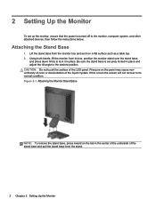
... LED panel. Using both hands, lift the monitor from the monitor box and set up the monitor, ensure that the power is securely locked in place and adjust the tilt angle to the desired position. If this occurs the screen will not recover to lock it on a flat surface such as a table top. 2. Attaching the Stand Base 1. Figure 2-1 Attaching the Monitor Stand Base NOTE: To remove the stand base, press inward on the panel...
... LED panel. Using both hands, lift the monitor from the monitor box and set up the monitor, ensure that the power is securely locked in place and adjust the tilt angle to the desired position. If this occurs the screen will not recover to lock it on a flat surface such as a table top. 2. Attaching the Stand Base 1. Figure 2-1 Attaching the Monitor Stand Base NOTE: To remove the stand base, press inward on the panel...
User Guide
Page 9
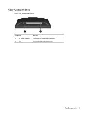
Rear Components Figure 2-2 Rear Components Component 1 AC Power Connector 2 VGA Function Connects the AC power cord to the monitor. Connects the VGA cable to the monitor. Rear Components 3
Rear Components Figure 2-2 Rear Components Component 1 AC Power Connector 2 VGA Function Connects the AC power cord to the monitor. Connects the VGA cable to the monitor. Rear Components 3

User Guide
Page 10
... outlet that no one end of electric shock or damage to an electrical wall outlet. For your safety, do not place anything on a cord or cable. Arrange them . Do not pull on power cords or cables. Connect the VGA signal cable. 3. The grounding plug is easily accessible at all times. Place the monitor in a convenient, well-ventilated location near the computer. 2. Disconnect...
... outlet that no one end of electric shock or damage to an electrical wall outlet. For your safety, do not place anything on a cord or cable. Arrange them . Do not pull on power cords or cables. Connect the VGA signal cable. 3. The grounding plug is easily accessible at all times. Place the monitor in a convenient, well-ventilated location near the computer. 2. Disconnect...
User Guide
Page 11
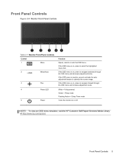
... Panel Controls Figure 2-4 Monitor Front Panel Controls Table 2-1 Monitor Front Panel Controls Control 1 Menu 2 Minus/Auto 3 Plus 4 Power LED 5 Power Function Opens, selects or exits the OSD menu. NOTE: To view an OSD menu simulator, visit the HP Customer Self Repair Services Media Library at http://www.hp.com/go/sml. Amber = Sleep mode Flashing Amber = Sleep Timer mode Turns the monitor on , press to select the highlighted menu item. If the OSD menu is on , press to navigate backward through the OSD menu and increase adjustment...
... Panel Controls Figure 2-4 Monitor Front Panel Controls Table 2-1 Monitor Front Panel Controls Control 1 Menu 2 Minus/Auto 3 Plus 4 Power LED 5 Power Function Opens, selects or exits the OSD menu. NOTE: To view an OSD menu simulator, visit the HP Customer Self Repair Services Media Library at http://www.hp.com/go/sml. Amber = Sleep mode Flashing Amber = Sleep Timer mode Turns the monitor on , press to select the highlighted menu item. If the OSD menu is on , press to navigate backward through the OSD menu and increase adjustment...

User Guide
Page 12
... that display the same static image on screen for a prolonged period of time.* To avoid burn-in image damage on the monitor screen, you should always activate a screen saver application or turn on all LED screens. Press the power button on the Monitor 1. Monitors with a "burned-in the OSD menu. Adjusting the Monitor Tilt the monitor panel forward or backward to set it to turn off the monitor when it is not in use for...
... that display the same static image on screen for a prolonged period of time.* To avoid burn-in image damage on the monitor screen, you should always activate a screen saver application or turn on all LED screens. Press the power button on the Monitor 1. Monitors with a "burned-in the OSD menu. Adjusting the Monitor Tilt the monitor panel forward or backward to set it to turn off the monitor when it is not in use for...

User Guide
Page 13
... rails on the rear that can remove the monitor panel from the back of the monitor. 2. Disconnect and remove the signal and power cables from the pedestal base to the monitor. Lay the monitor face down on a flat surface covered by a dry, clean cloth. Refer to be used to mount optional devices, such as the HP speaker bar, to attach to install the panel on a wall, a swing arm (sold separately), or...
... rails on the rear that can remove the monitor panel from the back of the monitor. 2. Disconnect and remove the signal and power cables from the pedestal base to the monitor. Lay the monitor face down on a flat surface covered by a dry, clean cloth. Refer to be used to mount optional devices, such as the HP speaker bar, to attach to install the panel on a wall, a swing arm (sold separately), or...

User Guide
Page 14
... monitor panel (2). CAUTION: This monitor supports the VESA industry standard 100 mm mounting holes. Figure 2-8 Installing the Monitor on the monitor. Figure 2-7 Removing the Pedestal Base 4. It is important to verify that the manufacturer's mounting solution is compliant with the VESA standard and is rated to support the weight of the monitor that the monitor is important to use the power and video cables provided with the mounting fixture to ensure that connect...
... monitor panel (2). CAUTION: This monitor supports the VESA industry standard 100 mm mounting holes. Figure 2-8 Installing the Monitor on the monitor. Figure 2-7 Removing the Pedestal Base 4. It is important to verify that the manufacturer's mounting solution is compliant with the VESA standard and is rated to support the weight of the monitor that the monitor is important to use the power and video cables provided with the mounting fixture to ensure that connect...

User Guide
Page 15
The rating labels are located on the monitor provide the spare part number, product number, and serial number. You may need these numbers when contacting HP about the monitor model. Figure 2-10 Installing a Cable Lock Locating the Rating Labels 9 Figure 2-9 Locating the Rating Labels Installing a Cable Lock You can secure the monitor to a fixed object with an optional cable lock available from HP (sold separately). Locating the Rating Labels The rating labels on the rear panel of the monitor.
The rating labels are located on the monitor provide the spare part number, product number, and serial number. You may need these numbers when contacting HP about the monitor model. Figure 2-10 Installing a Cable Lock Locating the Rating Labels 9 Figure 2-9 Locating the Rating Labels Installing a Cable Lock You can secure the monitor to a fixed object with an optional cable lock available from HP (sold separately). Locating the Rating Labels The rating labels on the rear panel of the monitor.

User Guide
Page 16
..., you can contact support. Select your country or region, select Product Support & Troubleshooting, and then enter your monitor, go /contactHP. NOTE: The monitor user guide, reference guide, and drivers are available at http://www.hp.com/ support. 3 Finding More Information Refer to the HP LCD Monitors Reference Guide included on using and adjusting your monitor model in English. ● Find e-mail support ● Find support telephone numbers ● Locate an HP service center 10 Chapter...
..., you can contact support. Select your country or region, select Product Support & Troubleshooting, and then enter your monitor, go /contactHP. NOTE: The monitor user guide, reference guide, and drivers are available at http://www.hp.com/ support. 3 Finding More Information Refer to the HP LCD Monitors Reference Guide included on using and adjusting your monitor model in English. ● Find e-mail support ● Find support telephone numbers ● Locate an HP service center 10 Chapter...

User Guide
Page 17
... typical specifications provided by HP's component manufacturers; Table 4-1 P19A Specifications Maximum Weight (Unpacked) 3.47 kg 7.65 lbs Dimensions (include stand) Height Depth Width 41.82 cm 20.64 cm 41.40 cm 16.46 inches 8.13 inches 16.3 inches Maximum Graphic Resolution 1280 x 1024 (60Hz) analog input Optimum Graphic Resolution 1280 x 1024 (60 Hz) analog input Power Source 100 - 240 VAC 50/60 Hz Input Terminal One VGA connector Tilt -5°...
... typical specifications provided by HP's component manufacturers; Table 4-1 P19A Specifications Maximum Weight (Unpacked) 3.47 kg 7.65 lbs Dimensions (include stand) Height Depth Width 41.82 cm 20.64 cm 41.40 cm 16.46 inches 8.13 inches 16.3 inches Maximum Graphic Resolution 1280 x 1024 (60Hz) analog input Optimum Graphic Resolution 1280 x 1024 (60 Hz) analog input Power Source 100 - 240 VAC 50/60 Hz Input Terminal One VGA connector Tilt -5°...

User Guide
Page 18
Entering User Modes The video controller signal may occasionally call for a mode that is not preset if you are not using a standard graphics adapter. 12 Chapter 4 Technical Specifications
Entering User Modes The video controller signal may occasionally call for a mode that is not preset if you are not using a standard graphics adapter. 12 Chapter 4 Technical Specifications
Setup Poster
Page 1
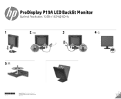
First Edition April 2013 The information contained herein is subject to change without notice. ProDisplay P19A LED Backlit Monitor Optimal Resolution: 1280 x 1024 @ 60 Hz 1 2 VGA 3 4 5 720603-B21 Copyright © 2013 Hewlett-Packard Development Company, L.P. Printed in xxxxx
First Edition April 2013 The information contained herein is subject to change without notice. ProDisplay P19A LED Backlit Monitor Optimal Resolution: 1280 x 1024 @ 60 Hz 1 2 VGA 3 4 5 720603-B21 Copyright © 2013 Hewlett-Packard Development Company, L.P. Printed in xxxxx


