

User Guide
Page 2
First Edition (November 2012) Document Part Number: 711877-001 This document contains proprietary information that is protected by copyright. Nothing herein should be liable for HP products and services are set forth in the express warranty statements accompanying such products and services. © 2012 Hewlett-Packard Development Company, L.P. HP shall not be construed as constituting an additional warranty...
First Edition (November 2012) Document Part Number: 711877-001 This document contains proprietary information that is protected by copyright. Nothing herein should be liable for HP products and services are set forth in the express warranty statements accompanying such products and services. © 2012 Hewlett-Packard Development Company, L.P. HP shall not be construed as constituting an additional warranty...

User Guide
Page 3
About This Guide This guide provides information on monitor features, setting up the monitor, and technical specifications. Text set off in this manner indicates that failure to follow directions could result in this manner indicates that failure to equipment or loss of life. CAUTION: Text set off in this manner provides important supplemental information. iii NOTE: Text set off in damage to follow directions could result in bodily harm or loss of information. WARNING!
About This Guide This guide provides information on monitor features, setting up the monitor, and technical specifications. Text set off in this manner indicates that failure to follow directions could result in this manner indicates that failure to equipment or loss of life. CAUTION: Text set off in this manner provides important supplemental information. iii NOTE: Text set off in damage to follow directions could result in bodily harm or loss of information. WARNING!
User Guide
Page 5
... 1 Product Features ...1 HP LCD Monitors ...1 2 Setting Up the Monitor ...3 Attaching the Stand Base ...3 Rear Components ...4 Connecting the Cables ...5 Front Panel Controls ...7 Adjusting the Monitor ...8 Turning on the Monitor ...8 Removing the Monitor Stand ...9 Mounting the Monitor 9 Installing a Cable Lock ...11 3 Finding More Information 12 Product Support ...12 4 Technical Specifications 13 P191 Model ...13 P201 and P201m Models ...13 P221 Model ...14 Preset Display Resolutions ...15 P191 Model ...15 P201 and P201m Models 15 P221 Model ...15 Entering User Modes ...17 Energy Saver...
... 1 Product Features ...1 HP LCD Monitors ...1 2 Setting Up the Monitor ...3 Attaching the Stand Base ...3 Rear Components ...4 Connecting the Cables ...5 Front Panel Controls ...7 Adjusting the Monitor ...8 Turning on the Monitor ...8 Removing the Monitor Stand ...9 Mounting the Monitor 9 Installing a Cable Lock ...11 3 Finding More Information 12 Product Support ...12 4 Technical Specifications 13 P191 Model ...13 P201 and P201m Models ...13 P221 Model ...14 Preset Display Resolutions ...15 P191 Model ...15 P201 and P201m Models 15 P221 Model ...15 Entering User Modes ...17 Energy Saver...
User Guide
Page 7
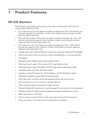
...● Removable stand for flexible monitor panel mounting solutions ● Video signal input to support VGA analog with VGA signal cable provided ● Video signal input to support DVI digital with 1920 x 1080 resolution, plus full-screen support for lower resolutions; includes custom scaling for maximum image size while preserving original aspect ratio ● P221 model, 55-cm (21.5-inch) diagonal viewable area display with DVI-D signal cable provided (select models) ● Integrated speakers and audio cable (select models) ● Supports an optional HP Speaker Bar, HP Quick...
...● Removable stand for flexible monitor panel mounting solutions ● Video signal input to support VGA analog with VGA signal cable provided ● Video signal input to support DVI digital with 1920 x 1080 resolution, plus full-screen support for lower resolutions; includes custom scaling for maximum image size while preserving original aspect ratio ● P221 model, 55-cm (21.5-inch) diagonal viewable area display with DVI-D signal cable provided (select models) ● Integrated speakers and audio cable (select models) ● Supports an optional HP Speaker Bar, HP Quick...

User Guide
Page 9
... stand base from the monitor box and set up the monitor, ensure that the power is turned off to the desired position. Attaching the Stand Base 3 Lift the stand base from the stand. Figure 2-1 Attaching the Monitor Stand Base NOTE: To remove the stand base, press inward on the tab in place and adjust the tilt angle to the monitor, computer system, and other attached devices, then follow the instructions below. 2 Setting Up the Monitor...
... stand base from the monitor box and set up the monitor, ensure that the power is turned off to the desired position. Attaching the Stand Base 3 Lift the stand base from the stand. Figure 2-1 Attaching the Monitor Stand Base NOTE: To remove the stand base, press inward on the tab in place and adjust the tilt angle to the monitor, computer system, and other attached devices, then follow the instructions below. 2 Setting Up the Monitor...

User Guide
Page 10
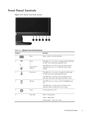
Connects the DVI-D cable to the monitor. Connects the audio cable to the monitor. Rear Components Figure 2-2 Rear Components Component 1 AC Power Connector 2 Audio Connector (select models) 3 DVI-D (select models) 4 VGA Function Connects the AC power cord to the monitor. 4 Chapter 2 Setting Up the Monitor Connects the VGA cable to the monitor.
Connects the DVI-D cable to the monitor. Connects the audio cable to the monitor. Rear Components Figure 2-2 Rear Components Component 1 AC Power Connector 2 Audio Connector (select models) 3 DVI-D (select models) 4 VGA Function Connects the AC power cord to the monitor. 4 Chapter 2 Setting Up the Monitor Connects the VGA cable to the monitor.

User Guide
Page 11
... inputs have valid video signals. Connect the DVI-D signal cable to the DVI connector on the rear of the monitor and the other end to the VGA connector on the rear of the clip (1), then lifting the clip off the stand (2). Remove the cable management clip from the stand by pressing the Menu button. ● For analog operation, use the DVI-D signal cable provided. Connect the VGA signal cable to the VGA connector on the computer. ● For DVI digital operation, use...
... inputs have valid video signals. Connect the DVI-D signal cable to the DVI connector on the rear of the monitor and the other end to the VGA connector on the rear of the clip (1), then lifting the clip off the stand (2). Remove the cable management clip from the stand by pressing the Menu button. ● For analog operation, use the DVI-D signal cable provided. Connect the VGA signal cable to the VGA connector on the computer. ● For DVI digital operation, use...

User Guide
Page 12
... the power cord from the equipment by the plug. 6. Figure 2-5 Installing the Cable Management Clip 6 Chapter 2 Setting Up the Monitor The grounding plug is easily accessible at all times. Do not pull on power cords or cables. Press the clip straight down on the stand ensuring that the tabs on or trip over them so that is an important safety feature. Connect one...
... the power cord from the equipment by the plug. 6. Figure 2-5 Installing the Cable Management Clip 6 Chapter 2 Setting Up the Monitor The grounding plug is easily accessible at all times. Do not pull on power cords or cables. Press the clip straight down on the stand ensuring that the tabs on or trip over them so that is an important safety feature. Connect one...
User Guide
Page 13
... activate the auto adjustment feature to optimize the screen image. Press - If the OSD menu is inactive, press to activate the volume adjustment bar. or + to activate the source button that chooses the video signal input (VGA or DVI). If the OSD menu is on , press to navigate backward through the OSD menu and increase adjustment levels. If the OSD menu is on or off. 6 Power LED White = Fully powered. Front Panel Controls Figure 2-6 Monitor Front Panel Controls Table 2-1 Monitor Front Panel Controls Control Function 1 Menu Opens, selects...
... activate the auto adjustment feature to optimize the screen image. Press - If the OSD menu is inactive, press to activate the volume adjustment bar. or + to activate the source button that chooses the video signal input (VGA or DVI). If the OSD menu is on , press to navigate backward through the OSD menu and increase adjustment levels. If the OSD menu is on or off. 6 Power LED White = Fully powered. Front Panel Controls Figure 2-6 Monitor Front Panel Controls Table 2-1 Monitor Front Panel Controls Control Function 1 Menu Opens, selects...

User Guide
Page 14
... monitor power button for a prolonged period of the auto-switch source setting (on the monitor. NOTE: You can disable the power LED in image" are not covered under the HP warranty. * A prolonged period of time is 12 consecutive hours of non-use for five seconds. factory default is on), the default source signal (factory default is the current active signal, the status of time.* To avoid burn-in image damage on the computer. 2. Adjusting the Monitor Tilt...
... monitor power button for a prolonged period of the auto-switch source setting (on the monitor. NOTE: You can disable the power LED in image" are not covered under the HP warranty. * A prolonged period of time is 12 consecutive hours of non-use for five seconds. factory default is on), the default source signal (factory default is the current active signal, the status of time.* To avoid burn-in image damage on the computer. 2. Adjusting the Monitor Tilt...

User Guide
Page 15
... on a wall, a swing arm, or other mounting fixture. Disconnect and remove the signal and power cables from the stand to the Monitor Mounting the Monitor The monitor panel can change the default source in the following order: DVI then VGA. Figure 2-8 Removing the Screws Attaching the Stand to install the panel on a flat surface covered by pressing the front panel Menu button and selecting Source Control > Default Source. The monitor automatically scans the signal inputs for an active input and uses that input for the display. Removing the Monitor Stand 9 If...
... on a wall, a swing arm, or other mounting fixture. Disconnect and remove the signal and power cables from the stand to the Monitor Mounting the Monitor The monitor panel can change the default source in the following order: DVI then VGA. Figure 2-8 Removing the Screws Attaching the Stand to install the panel on a flat surface covered by pressing the front panel Menu button and selecting Source Control > Default Source. The monitor automatically scans the signal inputs for an active input and uses that input for the display. Removing the Monitor Stand 9 If...

User Guide
Page 16
... Listed wall mount bracket. 1. CAUTION: This monitor supports the VESA industry standard 100 mm mounting holes. It is important to verify that the monitor is important to use the power and video cables provided with the VESA standard and is rated to support the weight of the monitor. Reconnect the cables to the monitor, four 4 mm, 0.7 pitch, and 10 mm long screws are required. Remove the stand from the monitor. NOTE...
... Listed wall mount bracket. 1. CAUTION: This monitor supports the VESA industry standard 100 mm mounting holes. It is important to verify that the monitor is important to use the power and video cables provided with the VESA standard and is rated to support the weight of the monitor. Reconnect the cables to the monitor, four 4 mm, 0.7 pitch, and 10 mm long screws are required. Remove the stand from the monitor. NOTE...

User Guide
Page 17
Installing a Cable Lock You can secure the monitor to a fixed object with an optional cable lock available from HP (sold separately). Figure 2-10 Installing a Cable Lock Installing a Cable Lock 11
Installing a Cable Lock You can secure the monitor to a fixed object with an optional cable lock available from HP (sold separately). Figure 2-10 Installing a Cable Lock Installing a Cable Lock 11
User Guide
Page 18
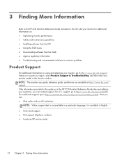
... your monitor for additional information on: ● Optimizing monitor performance ● Safety and maintenance guidelines ● Installing software from the CD ● Using the OSD menu ● Downloading software from the Web ● Agency regulatory information ● Troubleshooting and recommended solutions to common problems Product Support For additional information on using and adjusting your monitor model in English. ● Find e-mail support ● Find support telephone numbers ● Locate an HP service center...
... your monitor for additional information on: ● Optimizing monitor performance ● Safety and maintenance guidelines ● Installing software from the CD ● Using the OSD menu ● Downloading software from the Web ● Agency regulatory information ● Troubleshooting and recommended solutions to common problems Product Support For additional information on using and adjusting your monitor model in English. ● Find e-mail support ● Find support telephone numbers ● Locate an HP service center...

User Guide
Page 19
... Weight (Unpacked) 3.2 kg 7.1 lbs Dimensions (include stand) Height Depth Width 34.0 cm 14.3 cm 44.93 cm 13.4 inches 5.63 inches 17.69 inches Maximum Graphic Resolution 1366 x 768 (60 Hz) analog input Optimum Graphic Resolution 1366 x 768 (60 Hz) analog input Power Source 100 - 240 VAC 50/60 Hz Input Terminal One VGA connector with cable included Tilt 30° Operating Temperature 0° to 35° C 32...
... Weight (Unpacked) 3.2 kg 7.1 lbs Dimensions (include stand) Height Depth Width 34.0 cm 14.3 cm 44.93 cm 13.4 inches 5.63 inches 17.69 inches Maximum Graphic Resolution 1366 x 768 (60 Hz) analog input Optimum Graphic Resolution 1366 x 768 (60 Hz) analog input Power Source 100 - 240 VAC 50/60 Hz Input Terminal One VGA connector with cable included Tilt 30° Operating Temperature 0° to 35° C 32...
User Guide
Page 20
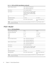
... ft above sea level NOTE: For more information, go to http://www.hp.com/go /productbulletin and search for your specific display model to find the model-specific QuickSpecs. one DVI connector with cable included; Table 4-2 P201 and P201m Specifications (continued) Optimum Graphic Resolution 1600 x 900 (60 Hz) analog input 1600 x 900 (60 Hz) digital input Power Source 100 - 240 VAC 50/60 Hz Input Terminal One VGA connector with cable included;
... ft above sea level NOTE: For more information, go to http://www.hp.com/go /productbulletin and search for your specific display model to find the model-specific QuickSpecs. one DVI connector with cable included; Table 4-2 P201 and P201m Specifications (continued) Optimum Graphic Resolution 1600 x 900 (60 Hz) analog input 1600 x 900 (60 Hz) digital input Power Source 100 - 240 VAC 50/60 Hz Input Terminal One VGA connector with cable included;

User Guide
Page 21
This monitor automatically recognizes these preset modes and they will appear properly sized and centered on the screen. Preset Display Resolutions The display resolutions listed below are the most commonly used modes and are set as factory defaults. P191 Model Table 4-4 Factory Preset Modes Preset Pixel Format Horz Freq (kHz) 1 640 × 480 31.47 2 720 ×...768 48.00 Vert Freq (Hz) 59.94 70.09 60.32 60.00 60.00 60.02 60.00 P201 and P201m Models Table 4-5 Factory Preset Modes Preset Pixel Format Horz Freq (kHz) 1 640 × 480 31.469 2 720 × 400 31.469 3 800...
This monitor automatically recognizes these preset modes and they will appear properly sized and centered on the screen. Preset Display Resolutions The display resolutions listed below are the most commonly used modes and are set as factory defaults. P191 Model Table 4-4 Factory Preset Modes Preset Pixel Format Horz Freq (kHz) 1 640 × 480 31.47 2 720 ×...768 48.00 Vert Freq (Hz) 59.94 70.09 60.32 60.00 60.00 60.02 60.00 P201 and P201m Models Table 4-5 Factory Preset Modes Preset Pixel Format Horz Freq (kHz) 1 640 × 480 31.469 2 720 × 400 31.469 3 800...

User Guide
Page 22
Table 4-6 Factory Preset Modes (continued) 2 720 × 400 31.469 70.087 3 800 × 600 37.879 60.317 4 1024 × 768 48.363 60.004 5 1280 × 720 45.00 60.00 6 1280 × 1024 63.981 60.02 7 1440 × 900 55.935 59.887 8 1600 × 900 60.00 60.00 9 1680 × 1050 65.29 59.954 10 1920 x 1080 67.50 60.00 16 Chapter 4 Technical Specifications
Table 4-6 Factory Preset Modes (continued) 2 720 × 400 31.469 70.087 3 800 × 600 37.879 60.317 4 1024 × 768 48.363 60.004 5 1280 × 720 45.00 60.00 6 1280 × 1024 63.981 60.02 7 1440 × 900 55.935 59.887 8 1600 × 900 60.00 60.00 9 1680 × 1050 65.29 59.954 10 1920 x 1080 67.50 60.00 16 Chapter 4 Technical Specifications

User Guide
Page 23
... monitor uses .5 watts of these modes and saved in memory. When the monitor is turned amber. The monitor automatically stores the new setting, then recognizes the new mode just as it detects the absence of one or both horizontal and vertical sync signals. Energy Saver Feature The monitors support a reduced power state. NOTE: The power saver feature only works when connected to the factory preset modes, there are not using a standard graphics adapter...
... monitor uses .5 watts of these modes and saved in memory. When the monitor is turned amber. The monitor automatically stores the new setting, then recognizes the new mode just as it detects the absence of one or both horizontal and vertical sync signals. Energy Saver Feature The monitors support a reduced power state. NOTE: The power saver feature only works when connected to the factory preset modes, there are not using a standard graphics adapter...

Setup Poster
Page 1
Printed in xxxxx First Edition October 2012 The information contained herein is subject to change without notice. ProDisplay LED Backlit Monitors Optimum Resolution P191: 1366 x 768 @ 60 Hz Optimum Resolution P201/P201m: 1600 x 900 @ 60 Hz Optimum Resolution P221: 1920 x 1080 @ 60 Hz 1 2 3 VGA DVI-D P201/P201m/P221 OR 4 5 P201m only 6 7 8 711876-B21 Copyright © 2012 Hewlett-Packard Development Company, L.P.
Printed in xxxxx First Edition October 2012 The information contained herein is subject to change without notice. ProDisplay LED Backlit Monitors Optimum Resolution P191: 1366 x 768 @ 60 Hz Optimum Resolution P201/P201m: 1600 x 900 @ 60 Hz Optimum Resolution P221: 1920 x 1080 @ 60 Hz 1 2 3 VGA DVI-D P201/P201m/P221 OR 4 5 P201m only 6 7 8 711876-B21 Copyright © 2012 Hewlett-Packard Development Company, L.P.


