
UPS R3000 XR Models User Guide
Page 10
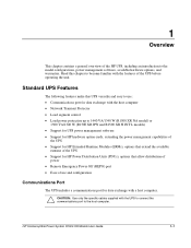
... the host computer • Support for power management software • Support for hardware option cards • Support for extended runtime modules (ERMs) • Support for power distribution units (PDUs) • Support for Remote Emergency Power Off (REPO) • Power protection for loads... UPS Features The following features make the UPS versatile and easy to 3000 VA/2700 W • Load segment control HP Uninterruptible Power System R3000 XR Models User Guide 1-1 1 Overview This chapter contains a general overview of the UPS, including power management software, available hardware ...
... the host computer • Support for power management software • Support for hardware option cards • Support for extended runtime modules (ERMs) • Support for power distribution units (PDUs) • Support for Remote Emergency Power Off (REPO) • Power protection for loads... UPS Features The following features make the UPS versatile and easy to 3000 VA/2700 W • Load segment control HP Uninterruptible Power System R3000 XR Models User Guide 1-1 1 Overview This chapter contains a general overview of the UPS, including power management software, available hardware ...
UPS R3000 XR Models User Guide
Page 13
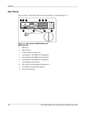
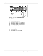
Overview Rear Panels The rear panels of the UPS models are shown in Figure 1-2 through Figure 1-7. 12 3 456 10 9 8 7 Figure 1-2: Rear panel of R3000 XR-NA and R3000 XR-JPN 1 REPO port 2 ERM connector 3 Communications port/option slot 4 Load segment 1 (two NEMA 5-15 receptacles) 5 Load segment 2 (two NEMA 5-15 receptacles) 6 Load segment 3 (two NEMA 5-15 receptacles) 7 Load segment circuit protectors 8 PDU output (L5-30) receptacle (load segment 1) 9 Cord retention clip attachment locations 10 Ground bonding screw 1-4 HP Uninterruptible Power System R3000 XR Models User Guide
Overview Rear Panels The rear panels of the UPS models are shown in Figure 1-2 through Figure 1-7. 12 3 456 10 9 8 7 Figure 1-2: Rear panel of R3000 XR-NA and R3000 XR-JPN 1 REPO port 2 ERM connector 3 Communications port/option slot 4 Load segment 1 (two NEMA 5-15 receptacles) 5 Load segment 2 (two NEMA 5-15 receptacles) 6 Load segment 3 (two NEMA 5-15 receptacles) 7 Load segment circuit protectors 8 PDU output (L5-30) receptacle (load segment 1) 9 Cord retention clip attachment locations 10 Ground bonding screw 1-4 HP Uninterruptible Power System R3000 XR Models User Guide
UPS R3000 XR Models User Guide
Page 14
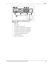
12 3 456 10 9 8 7 Figure 1-3: Rear panel of R3000h XR-NA and R3000h XR-JPN 1 REPO port 2 ERM connector 3 Communications port/option slot 4 Load segment 1 (three IEC-320-C13 receptacles) 5 Load segment 2 (three IEC-320-C13 receptacles) 6 Load segment 3 (three IEC-320-C13 receptacles) 7 PDU output (L6-20) receptacle (load segment 1) 8 Cord retention clip attachment locations 9 Ground bonding screw 10 Power cord with L6-20 plug Overview HP Uninterruptible Power System R3000 XR Models User Guide 1-5
12 3 456 10 9 8 7 Figure 1-3: Rear panel of R3000h XR-NA and R3000h XR-JPN 1 REPO port 2 ERM connector 3 Communications port/option slot 4 Load segment 1 (three IEC-320-C13 receptacles) 5 Load segment 2 (three IEC-320-C13 receptacles) 6 Load segment 3 (three IEC-320-C13 receptacles) 7 PDU output (L6-20) receptacle (load segment 1) 8 Cord retention clip attachment locations 9 Ground bonding screw 10 Power cord with L6-20 plug Overview HP Uninterruptible Power System R3000 XR Models User Guide 1-5

UPS R3000 XR Models User Guide
Page 15
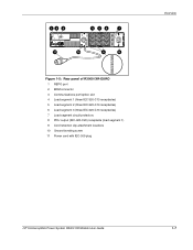
Overview 12 3 456 7 11 10 9 8 Figure 1-4: Rear panel of R3000e XR-INT 1 REPO port 2 ERM connector 3 Communications port/option slot 4 Load segment 1 (three IEC-320-C13 receptacles) 5 Load segment 2 (three IEC-320-C13 receptacles) 6 Load segment 3 (three IEC-320-C13 ... earth (ground) conductor leakage current for all connected devices exceeds 3.5 mA. If the total earth (ground) conductor leakage current exceeds 3.5 mA, use the UPS R3000i XR-EURO, R3000i XR-SCHUKO, or R3000i XR-SA model. 1-6 HP Uninterruptible Power System R3000 XR Models User Guide
Overview 12 3 456 7 11 10 9 8 Figure 1-4: Rear panel of R3000e XR-INT 1 REPO port 2 ERM connector 3 Communications port/option slot 4 Load segment 1 (three IEC-320-C13 receptacles) 5 Load segment 2 (three IEC-320-C13 receptacles) 6 Load segment 3 (three IEC-320-C13 ... earth (ground) conductor leakage current for all connected devices exceeds 3.5 mA. If the total earth (ground) conductor leakage current exceeds 3.5 mA, use the UPS R3000i XR-EURO, R3000i XR-SCHUKO, or R3000i XR-SA model. 1-6 HP Uninterruptible Power System R3000 XR Models User Guide
UPS R3000 XR Models User Guide
Page 16
12 3 456 7 11 10 9 8 Figure 1-5: Rear panel of R3000i XR-EURO 1 REPO port 2 ERM connector 3 Communications port/option slot 4 Load segment 1 (three IEC-320-C13 receptacles) 5 Load segment 2 (three IEC-320-C13 receptacles) 6 Load segment 3 (three IEC-320-C13 receptacles) 7 Load segment circuit protectors 8 PDU output (IEC-320-C20) receptacle (load segment 1) 9 Cord retention clip attachment locations 10 Ground bonding screw 11 Power cord with IEC-309 plug Overview HP Uninterruptible Power System R3000 XR Models User Guide 1-7
12 3 456 7 11 10 9 8 Figure 1-5: Rear panel of R3000i XR-EURO 1 REPO port 2 ERM connector 3 Communications port/option slot 4 Load segment 1 (three IEC-320-C13 receptacles) 5 Load segment 2 (three IEC-320-C13 receptacles) 6 Load segment 3 (three IEC-320-C13 receptacles) 7 Load segment circuit protectors 8 PDU output (IEC-320-C20) receptacle (load segment 1) 9 Cord retention clip attachment locations 10 Ground bonding screw 11 Power cord with IEC-309 plug Overview HP Uninterruptible Power System R3000 XR Models User Guide 1-7
UPS R3000 XR Models User Guide
Page 17
Overview 12 3 456 7 11 10 9 8 Figure 1-6: Rear panel of R3000i XR-SCHUKO 1 REPO port 2 ERM connector 3 Communications port/option slot 4 Load segment 1 (three IEC-320-C13 receptacles) 5 Load segment 2 (three IEC-320-C13 receptacles) 6 Load segment 3 (three IEC-320-C13 receptacles) 7 Load segment circuit protectors 8 PDU output (IEC-320-C20) receptacle (load segment 1) 9 Cord retention clip attachment locations 10 Ground bonding screw 11 Power cord with CEE 7/7 SCHUKO plug 1-8 HP Uninterruptible Power System R3000 XR Models User Guide
Overview 12 3 456 7 11 10 9 8 Figure 1-6: Rear panel of R3000i XR-SCHUKO 1 REPO port 2 ERM connector 3 Communications port/option slot 4 Load segment 1 (three IEC-320-C13 receptacles) 5 Load segment 2 (three IEC-320-C13 receptacles) 6 Load segment 3 (three IEC-320-C13 receptacles) 7 Load segment circuit protectors 8 PDU output (IEC-320-C20) receptacle (load segment 1) 9 Cord retention clip attachment locations 10 Ground bonding screw 11 Power cord with CEE 7/7 SCHUKO plug 1-8 HP Uninterruptible Power System R3000 XR Models User Guide

UPS R3000 XR Models User Guide
Page 18
12 3 456 7 11 10 9 8 Figure 1-7: Rear panel of R3000i XR-SA 1 REPO port 2 ERM connector 3 Communications port/option slot 4 Load segment 1 (three IEC-320-C13 receptacles) 5 Load segment 2 (three IEC-320-C13 receptacles) 6 Load segment 3 (three IEC-320-C13 receptacles) 7 Load segment circuit protectors 8 PDU output (IEC-320-C20) receptacle (load segment 1) 9 Cord retention clip attachment locations 10 Ground bonding screw 11 Input power receptacle with BS-546 power cord Overview HP Uninterruptible Power System R3000 XR Models User Guide 1-9
12 3 456 7 11 10 9 8 Figure 1-7: Rear panel of R3000i XR-SA 1 REPO port 2 ERM connector 3 Communications port/option slot 4 Load segment 1 (three IEC-320-C13 receptacles) 5 Load segment 2 (three IEC-320-C13 receptacles) 6 Load segment 3 (three IEC-320-C13 receptacles) 7 Load segment circuit protectors 8 PDU output (IEC-320-C20) receptacle (load segment 1) 9 Cord retention clip attachment locations 10 Ground bonding screw 11 Input power receptacle with BS-546 power cord Overview HP Uninterruptible Power System R3000 XR Models User Guide 1-9

UPS R3000 XR Models User Guide
Page 19
...refer to sequence the startup of system components • Customizes alert generation with the UPS. For more information, refer to the HP UPS XR Products Power Cord and Options Reference Guide included on the Power Products Documentation CD and on a user-specified schedule • Delays... Shuts down and reboots any UPS and attached equipment based on www.hp.com. 1-10 HP Uninterruptible Power System R3000 XR Models User Guide Table 1-2: Hardware Options Option Part Number HP ERM 192188-B21 HP Six Port Card 192185-B21 HP SNMP/Serial Port Card 192189-B21 Note: For a list of UPSs...
...refer to sequence the startup of system components • Customizes alert generation with the UPS. For more information, refer to the HP UPS XR Products Power Cord and Options Reference Guide included on the Power Products Documentation CD and on a user-specified schedule • Delays... Shuts down and reboots any UPS and attached equipment based on www.hp.com. 1-10 HP Uninterruptible Power System R3000 XR Models User Guide Table 1-2: Hardware Options Option Part Number HP ERM 192188-B21 HP Six Port Card 192185-B21 HP SNMP/Serial Port Card 192189-B21 Note: For a list of UPSs...

UPS R3000 XR Models User Guide
Page 57
.... Specifications Battery Specifications Table C-5: Battery Specifications Feature Type Voltage Charging Specification Each model contains maintenance-free, sealed, valve regulated lead-acid (VRLA) batteries with ERM Runtime (Minutes) 120 45 30 20 HP Uninterruptible Power System R3000 XR Models User Guide C-5 The battery module has a battery string voltage of 120 V. Complete charge takes no load.
.... Specifications Battery Specifications Table C-5: Battery Specifications Feature Type Voltage Charging Specification Each model contains maintenance-free, sealed, valve regulated lead-acid (VRLA) batteries with ERM Runtime (Minutes) 120 45 30 20 HP Uninterruptible Power System R3000 XR Models User Guide C-5 The battery module has a battery string voltage of 120 V. Complete charge takes no load.
UPS R1500 XR Models User Guide
Page 10
... model) or 1500 VA/1340 W (R1500 XR JPN and R1500 XR H INT'L models) • Support for UPS power management software • Support for HP hardware option cards, extending the power management capabilities of the UPS • Support for HP Extended Runtime Modules (ERMs), options that allow distribution of power • Remote Emergency Power Off (REPO...
... model) or 1500 VA/1340 W (R1500 XR JPN and R1500 XR H INT'L models) • Support for UPS power management software • Support for HP hardware option cards, extending the power management capabilities of the UPS • Support for HP Extended Runtime Modules (ERMs), options that allow distribution of power • Remote Emergency Power Off (REPO...

UPS R1500 XR Models User Guide
Page 13
Overview Rear Panels The rear panel configurations of the UPS are shown in Figures 1-2, 1-3, and 1-4. 1 2 3 10 9 8 7 65 4 Figure 1-2: Rear panel of R1500 XR NA 1 Communications port/option slot 2 Load segment circuit protectors 3 Load segment 2 (three NEMA 5-15 receptacles) 4 Load segment 1 (three NEMA 5-15 receptacles) 5 Network Transient Protector OUT jack 6 Network Transient Protector IN jack 7 REPO port 8 Power cord with NEMA 5-15 plug 9 ERM connector 10 Ground bonding screw 1-4 HP Uninterruptible Power System R1500 XR Models User Guide
Overview Rear Panels The rear panel configurations of the UPS are shown in Figures 1-2, 1-3, and 1-4. 1 2 3 10 9 8 7 65 4 Figure 1-2: Rear panel of R1500 XR NA 1 Communications port/option slot 2 Load segment circuit protectors 3 Load segment 2 (three NEMA 5-15 receptacles) 4 Load segment 1 (three NEMA 5-15 receptacles) 5 Network Transient Protector OUT jack 6 Network Transient Protector IN jack 7 REPO port 8 Power cord with NEMA 5-15 plug 9 ERM connector 10 Ground bonding screw 1-4 HP Uninterruptible Power System R1500 XR Models User Guide

UPS R1500 XR Models User Guide
Page 14
1 2 3 10 9 8 7 65 4 Figure 1-3: Rear panel of R1500 XR JPN 1 Communications port/option slot 2 Load segment circuit protectors 3 Load segment 2 (three NEMA 5-15 receptacles) 4 Load segment 1 (three NEMA 5-15 receptacles) 5 Network Transient Protector OUT jack 6 Network Transient Protector IN jack 7 REPO port 8 Power cord with NEMA 5-20 plug 9 ERM connector 10 Ground bonding screw Overview HP Uninterruptible Power System R1500 XR Models User Guide 1-5
1 2 3 10 9 8 7 65 4 Figure 1-3: Rear panel of R1500 XR JPN 1 Communications port/option slot 2 Load segment circuit protectors 3 Load segment 2 (three NEMA 5-15 receptacles) 4 Load segment 1 (three NEMA 5-15 receptacles) 5 Network Transient Protector OUT jack 6 Network Transient Protector IN jack 7 REPO port 8 Power cord with NEMA 5-20 plug 9 ERM connector 10 Ground bonding screw Overview HP Uninterruptible Power System R1500 XR Models User Guide 1-5

UPS R1500 XR Models User Guide
Page 15
...of R1500 XR H INT'L 1 Communications port/option slot 2 Circuit protector 3 IEC-320-C14 input power receptacle 4 Load segment 1 (three IEC-320-C13 receptacles) 5 Load segment 2 (three IEC-320-C13 receptacles) 6 Network Transient Protector OUT jack 7 Network Transient Protector IN jack 8 REPO port 9 ERM connector ...10 Ground bonding screw WARNING: Risk of personal injury from electric shock. This model is not suitable for installation where the total earth (ground) conductor leakage current for all connected devices exceeds 3.5 mA. Use RackBuilder Pro (obtainable at www.hp.com)...
...of R1500 XR H INT'L 1 Communications port/option slot 2 Circuit protector 3 IEC-320-C14 input power receptacle 4 Load segment 1 (three IEC-320-C13 receptacles) 5 Load segment 2 (three IEC-320-C13 receptacles) 6 Network Transient Protector OUT jack 7 Network Transient Protector IN jack 8 REPO port 9 ERM connector ...10 Ground bonding screw WARNING: Risk of personal injury from electric shock. This model is not suitable for installation where the total earth (ground) conductor leakage current for all connected devices exceeds 3.5 mA. Use RackBuilder Pro (obtainable at www.hp.com)...

UPS R1500 XR Models User Guide
Page 16
...HP UPSs. HP Uninterruptible Power System R1500 XR Models User Guide 1-7 Overview Power Management Software Power management software ensures maximum power reliability of HP computer systems through comprehensive control of the UPS and performs UPS diagnostics • Displays power logs for this UPS. Table 1-2: Hardware Options Option HP ERM HP Six Port Card HP...the startup of supported PDUs and more information on the available hardware options, refer to the HP UPS XR Products Power Cord and Options Reference Guide included on a user-specified schedule • Delays restart ...
...HP UPSs. HP Uninterruptible Power System R1500 XR Models User Guide 1-7 Overview Power Management Software Power management software ensures maximum power reliability of HP computer systems through comprehensive control of the UPS and performs UPS diagnostics • Displays power logs for this UPS. Table 1-2: Hardware Options Option HP ERM HP Six Port Card HP...the startup of supported PDUs and more information on the available hardware options, refer to the HP UPS XR Products Power Cord and Options Reference Guide included on a user-specified schedule • Delays restart ...

UPS R1500 XR ERM Installation Instructions
Page 1
... of this product, read the Important Safety Information document provided. WARNING: • The installation of the ERM. The ERM consists of any kind and is unstable when not fastened to align the rails. hp ups R1500 xr models extended runtime module installation instructions Read Instructions Completely Before Beginning Installation Procedures Overview These instructions show...
... of this product, read the Important Safety Information document provided. WARNING: • The installation of the ERM. The ERM consists of any kind and is unstable when not fastened to align the rails. hp ups R1500 xr models extended runtime module installation instructions Read Instructions Completely Before Beginning Installation Procedures Overview These instructions show...

UPS R12000 XR ERM Installation Instructions
Page 1
... installing this product must be unstable when not fastened to the rails. • Remove all batteries to insert battery modules into the ERM chassis. 221272- 002 hp ups r12000 xr models extended runtime module installation instructions Second Edition (December 2002) Part Number 221272-002 Overview These instructions show how to the series number...
... installing this product must be unstable when not fastened to the rails. • Remove all batteries to insert battery modules into the ERM chassis. 221272- 002 hp ups r12000 xr models extended runtime module installation instructions Second Edition (December 2002) Part Number 221272-002 Overview These instructions show how to the series number...

UPS R12000 XR Models User Guide
Page 10
...LCD display • Software shipped with the features of the UPS, including an introduction to power HP Power Distribution Units (PDUs) HP Uninterruptible Power System R12000 XR Models User Guide 1-1 Read this UPS versatile and easy to use: • Single phase,... 200-240 V, Unity rated • Parallel redundant (N+x) capabilities in the following features make this chapter to become familiar with the unit • Support for HP Extended Runtime Modules (ERMs...
...LCD display • Software shipped with the features of the UPS, including an introduction to power HP Power Distribution Units (PDUs) HP Uninterruptible Power System R12000 XR Models User Guide 1-1 Read this UPS versatile and easy to use: • Single phase,... 200-240 V, Unity rated • Parallel redundant (N+x) capabilities in the following features make this chapter to become familiar with the unit • Support for HP Extended Runtime Modules (ERMs...

UPS R12000 XR Models User Guide
Page 14
... the timing of system components. • Customizes alert generation with the UPS. Table 1-1: Hardware Options Option HP ERM PDU 40 A WW mPDU 40 A WW Part Number 217800-B21 207590-B23 252663-B21 HP Uninterruptible Power System R12000 XR Models User Guide 1-5 For the most current information, refer to sequence the startup of equipment shutdowns...
... the timing of system components. • Customizes alert generation with the UPS. Table 1-1: Hardware Options Option HP ERM PDU 40 A WW mPDU 40 A WW Part Number 217800-B21 207590-B23 252663-B21 HP Uninterruptible Power System R12000 XR Models User Guide 1-5 For the most current information, refer to sequence the startup of equipment shutdowns...

UPS R12000 XR Models User Guide
Page 15
...wired, the REPO feature allows the power at the UPS output receptacles to be active as long as the On button is held. 1-6 HP Uninterruptible Power System R12000 XR Models User Guide IMPORTANT: • The REPO port meets the requirements of the UPS. Power Distribution Units The UPS supports up to ... pressed and a REPO is detected, battery start and the UPS would assume the load. For more information, refer to the HP website at the recommended 80 percent load, one ERM will not be available to the devices until utility power is restored and the UPS has been manually powered up to...
...wired, the REPO feature allows the power at the UPS output receptacles to be active as long as the On button is held. 1-6 HP Uninterruptible Power System R12000 XR Models User Guide IMPORTANT: • The REPO port meets the requirements of the UPS. Power Distribution Units The UPS supports up to ... pressed and a REPO is detected, battery start and the UPS would assume the load. For more information, refer to the HP website at the recommended 80 percent load, one ERM will not be available to the devices until utility power is restored and the UPS has been manually powered up to...
UPS R12000 XR Models User Guide
Page 29
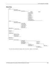
... Power Off System Normal Load Power On On Battery On Bypass Manual Bypass OverLoad Autocalibrating Starting Up Module Failure Unknown Stats xx UPS Supporting Load ERM Setup Commission Battery Parallel Mode Alarms * Serial Port 1 Serial Port 2 Opt-Slot 1 Opt-Slot 2 For Capacity N+1 Redundancy * For a list of all possible alarm displays, refer...
... Power Off System Normal Load Power On On Battery On Bypass Manual Bypass OverLoad Autocalibrating Starting Up Module Failure Unknown Stats xx UPS Supporting Load ERM Setup Commission Battery Parallel Mode Alarms * Serial Port 1 Serial Port 2 Opt-Slot 1 Opt-Slot 2 For Capacity N+1 Redundancy * For a list of all possible alarm displays, refer...