

HP UPS R3000 User Guide
Page 27
... the On button. To place the UPS in Standby mode, press and hold the Standby button until utility power is available at the UPS output receptacles. Power to the load ceases. The Utility LED turns solid green, indicating that power is available at the UPS receptacles. • The UPS charges the... placed in Standby mode when the UPS is in Standby mode until an alternate mode is selected or until the audible alarm sounds and the Utility LED flashes. For the location of operation: • Standby mode (on page 27) • Operate mode (on page 27) • Configure mode (on page 28...
... the On button. To place the UPS in Standby mode, press and hold the Standby button until utility power is available at the UPS output receptacles. Power to the load ceases. The Utility LED turns solid green, indicating that power is available at the UPS receptacles. • The UPS charges the... placed in Standby mode when the UPS is in Standby mode until an alternate mode is selected or until the audible alarm sounds and the Utility LED flashes. For the location of operation: • Standby mode (on page 27) • Operate mode (on page 27) • Configure mode (on page 28...
HP UPS R3000 User Guide
Page 28
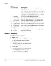
...UPS reaches a percentage greater than 110 percent for more than 10 cycles or between 103 percent and 110 percent for the number of LEDs, see the HP website (http://www.hp.com/go/rackandpower). To place the UPS in Configure mode (on page 28), and use the ERM configurator tool. For the location... solid green. Press and hold the On button until the audible alarm sounds. • If the UPS is off (no utility power is present and the Utility LED is available at the UPS receptacles. • The UPS charges the batteries as necessary. • The UPS configuration can also be updated. If the ...
...UPS reaches a percentage greater than 110 percent for more than 10 cycles or between 103 percent and 110 percent for the number of LEDs, see the HP website (http://www.hp.com/go/rackandpower). To place the UPS in Configure mode (on page 28), and use the ERM configurator tool. For the location... solid green. Press and hold the On button until the audible alarm sounds. • If the UPS is off (no utility power is present and the Utility LED is available at the UPS receptacles. • The UPS charges the batteries as necessary. • The UPS configuration can also be updated. If the ...

HP UPS R3000 User Guide
Page 29
...configuration. NOTE: Only one parameter automatically sets the other possibilities to Off. 4. UPS operations 29 The LED illuminates solid green. To configure the UPS for any one nominal utility voltage can be enabled for line-to-neutral connections. To save the configuration settings and exit Configure mode... level is set to 127/240 VAC Audible alarm will cause a false alarm. 5. If reconfiguring a 230 V unit to the Utility LED, then press the Standby button. A flashing green cursor indicates where you scroll through the available settings. 2. To change the UPS configuration...
...configuration. NOTE: Only one parameter automatically sets the other possibilities to Off. 4. UPS operations 29 The LED illuminates solid green. To configure the UPS for any one nominal utility voltage can be enabled for line-to-neutral connections. To save the configuration settings and exit Configure mode... level is set to 127/240 VAC Audible alarm will cause a false alarm. 5. If reconfiguring a 230 V unit to the Utility LED, then press the Standby button. A flashing green cursor indicates where you scroll through the available settings. 2. To change the UPS configuration...
HP UPS R3000 User Guide
Page 31
The General Alarm LED and Utility LED ("UPS front panel LED indicators" on page 7). Power up normally. 2. Reconnect the REPO port. Verify proper connection of Operate mode. c. Check and correct the connections. Powering down all load ... REPO port, the UPS powers up the UPS ("Starting power to discharge. Power to sound may still exist. • If a utility power failure caused the alarm (the Utility LED or the General Alarm LED illuminates red), the alarm silences after power is correct, the REPO connectors can be disconnected, and then reconnected, without initiating...
The General Alarm LED and Utility LED ("UPS front panel LED indicators" on page 7). Power up normally. 2. Reconnect the REPO port. Verify proper connection of Operate mode. c. Check and correct the connections. Powering down all load ... REPO port, the UPS powers up the UPS ("Starting power to discharge. Power to sound may still exist. • If a utility power failure caused the alarm (the Utility LED or the General Alarm LED illuminates red), the alarm silences after power is correct, the REPO connectors can be disconnected, and then reconnected, without initiating...

HP UPS R3000 User Guide
Page 41
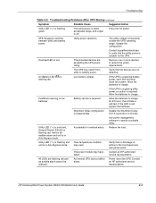
... audible alarm troubleshooting Genera l Alarm LED On Batter y LED Batter y Fault LED Site Wiring Fault LED Utility LED Overloa d LED Audible alarm Off Off Off Off Green Off Off Off Off Off Flashin Off g green Off Off Off Off Red Off Flashing Off Off Off ..." on page 42) Yes Bypass is out of range (on page 43) Yes Battery test failure ("Battery condition" on page 43) No Low battery (no utility power) ("UPS is on battery" on page 43) Yes Batteries are disconnected ("Battery condition" on page 43) Yes On battery-No...
... audible alarm troubleshooting Genera l Alarm LED On Batter y LED Batter y Fault LED Site Wiring Fault LED Utility LED Overloa d LED Audible alarm Off Off Off Off Green Off Off Off Off Off Flashin Off g green Off Off Off Off Red Off Flashing Off Off Off ..." on page 42) Yes Bypass is out of range (on page 43) Yes Battery test failure ("Battery condition" on page 43) No Low battery (no utility power) ("UPS is on battery" on page 43) Yes Batteries are disconnected ("Battery condition" on page 43) Yes On battery-No...

HP UPS R3000 User Guide
Page 65
...19 series number 55 settings 30 shipping the UPS 14 site requirements 14 site wiring condition 44 Site Wiring Fault LED, location 8 Site Wiring Fault LED, troubleshooting 41 software 32 spare part numbers 50, 51 spares 50 specifications 46 Standby button, location 7 Standby mode... UPS firmware, updating 39 UPS is on battery 43 UPS operations 27 UPS, installing 13, 18 UPS, replacing 38 Utility LED, location 8 Utility LED, troubleshooting 41 utility power condition 44 utility power, connecting 22 V voltage specifications 47 voltage, configuring 28, 30 W warranties 53 weight, battery 35 weight, ERM...
...19 series number 55 settings 30 shipping the UPS 14 site requirements 14 site wiring condition 44 Site Wiring Fault LED, location 8 Site Wiring Fault LED, troubleshooting 41 software 32 spare part numbers 50, 51 spares 50 specifications 46 Standby button, location 7 Standby mode... UPS firmware, updating 39 UPS is on battery 43 UPS operations 27 UPS, installing 13, 18 UPS, replacing 38 Utility LED, location 8 Utility LED, troubleshooting 41 utility power condition 44 utility power, connecting 22 V voltage specifications 47 voltage, configuring 28, 30 W warranties 53 weight, battery 35 weight, ERM...
UPS R12000 XR Backplate Receptacle Kit Installation Instructions
Page 2
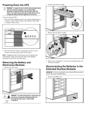
Removing the Battery and Electronics Modules 1. The load relays open, and the Utility LED (1) begins to remove the remaining battery and electronics modules. Disconnect the AC mains by pressing the Standby button for removing the battery module, which ... personal injury while performing this document. Remove the battery module. 3. Disconnecting the Batteries in Standby mode by opening the switch or circuit breaker at the utility panel and Lockout/Tagout. Refer to the UPS, disconnect the ERM batteries. 1. Powering Down the UPS WARNING: To reduce the risk of this procedure,...
Removing the Battery and Electronics Modules 1. The load relays open, and the Utility LED (1) begins to remove the remaining battery and electronics modules. Disconnect the AC mains by pressing the Standby button for removing the battery module, which ... personal injury while performing this document. Remove the battery module. 3. Disconnecting the Batteries in Standby mode by opening the switch or circuit breaker at the utility panel and Lockout/Tagout. Refer to the UPS, disconnect the ERM batteries. 1. Powering Down the UPS WARNING: To reduce the risk of this procedure,...

UPS R12000 XR Backplate Receptacle Kit Installation Instructions
Page 5
... (with approximately 10 seconds between modules), synching up the UPS. Replace the battery and electronics modules. Powering Up the UPS 1. The Utility LED (1) rapidly flashes green during this process, the UPS will remain in Standby mode indefinitely until the UPS On command is NOT in Standby... mode and continue to the HP website at the service panel by the Utility LED (1) slowly flashing green, after all electronics modules have synchronized. - To reconnect the batteries in the ERM, reverse ...
... (with approximately 10 seconds between modules), synching up the UPS. Replace the battery and electronics modules. Powering Up the UPS 1. The Utility LED (1) rapidly flashes green during this process, the UPS will remain in Standby mode indefinitely until the UPS On command is NOT in Standby... mode and continue to the HP website at the service panel by the Utility LED (1) slowly flashing green, after all electronics modules have synchronized. - To reconnect the batteries in the ERM, reverse ...

UPS R3000 XR Models User Guide
Page 23
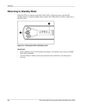
... of operation: • Standby Mode - Power is incorrect. Flashing Green-Utility voltage is present, and output is off ). Power is in Standby mode. The UPS batteries may need to be updated. 2-2 HP Uninterruptible Power System R3000 XR Models User Guide UPS is available at the ... Auto-Bypass mode. Operation continued Item Description 7 On Battery 8 Bad Battery/Low Battery 9 Site Wiring Fault Indicator 10 Utility LED 11 Configure Mode On LED 12 Configure button 13 Test/Alarm Reset button 14 Standby button 15 On button Meaning/Function Red-UPS is running on or...
... of operation: • Standby Mode - Power is incorrect. Flashing Green-Utility voltage is present, and output is off ). Power is in Standby mode. The UPS batteries may need to be updated. 2-2 HP Uninterruptible Power System R3000 XR Models User Guide UPS is available at the ... Auto-Bypass mode. Operation continued Item Description 7 On Battery 8 Bad Battery/Low Battery 9 Site Wiring Fault Indicator 10 Utility LED 11 Configure Mode On LED 12 Configure button 13 Test/Alarm Reset button 14 Standby button 15 On button Meaning/Function Red-UPS is running on or...

UPS R3000 XR Models User Guide
Page 24
...mode if either of their capacity within 24 hours Charge the batteries for 30 seconds. - Press and hold the On button (1) until the Utility LED (2) turns solid green, indicating that power is available. Operation • Auto-Bypass Mode - Charging the Batteries When the UPS is in Standby ... flashing green). • The UPS is powered down and no utility power present), press and hold the On button (1) until the audible alarm sounds. 2 1 100% 25% Figure 2-2: Placing the UPS in Operate Mode HP Uninterruptible Power System R3000 XR Models User Guide 2-3 The UPS power module fails ...
...mode if either of their capacity within 24 hours Charge the batteries for 30 seconds. - Press and hold the On button (1) until the Utility LED (2) turns solid green, indicating that power is available. Operation • Auto-Bypass Mode - Charging the Batteries When the UPS is in Standby ... flashing green). • The UPS is powered down and no utility power present), press and hold the On button (1) until the audible alarm sounds. 2 1 100% 25% Figure 2-2: Placing the UPS in Operate Mode HP Uninterruptible Power System R3000 XR Models User Guide 2-3 The UPS power module fails ...
UPS R3000 XR Models User Guide
Page 25
... power is available at the output receptacles. • The UPS remains in Operate mode (the Utility LED is solid green), press and hold the Standby button (1) until utility power is selected or until the audible alarm sounds. The Utility LED (2) flashes, and power to Standby Mode When the UPS is in Standby mode until an...
... power is available at the output receptacles. • The UPS remains in Operate mode (the Utility LED is solid green), press and hold the Standby button (1) until utility power is selected or until the audible alarm sounds. The Utility LED (2) flashes, and power to Standby Mode When the UPS is in Standby mode until an...
UPS R3000 XR Models User Guide
Page 28
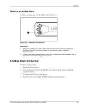
...Standby button to Chapter 5, "Troubleshooting." • If a utility power failure caused the alarm (Utility LED or General Alarm LED illuminates red), the alarm will be silenced after utility power is restored. Disconnect the UPS from utility power. 4. Silencing an Audible Alarm To silence an alarm..., press the Test/Alarm Reset button (1). HP Uninterruptible Power System...
...Standby button to Chapter 5, "Troubleshooting." • If a utility power failure caused the alarm (Utility LED or General Alarm LED illuminates red), the alarm will be silenced after utility power is restored. Disconnect the UPS from utility power. 4. Silencing an Audible Alarm To silence an alarm..., press the Test/Alarm Reset button (1). HP Uninterruptible Power System...

UPS R3000 XR Models User Guide
Page 30
...200-208 VAC. The configuration parameters are listed in Table 3-2. Table 3-1: Configuration Parameters/LED Indicators Parameter (LED) General Alarm Parameter Name 100/200-208 Nom Explanation (when illuminated) Nominal utility voltage level is not available on the R3000j XR-JPN, R3000h XR-NA, and ...are defined in Configure mode Configuration Parameters In Configure mode, the front panel LED display changes function to operate at 208 V, the Site Wiring Fault function must be manually disabled. 3-2 HP Uninterruptible Power System R3000 XR Models User Guide When the button is 120/230...
...200-208 VAC. The configuration parameters are listed in Table 3-2. Table 3-1: Configuration Parameters/LED Indicators Parameter (LED) General Alarm Parameter Name 100/200-208 Nom Explanation (when illuminated) Nominal utility voltage level is not available on the R3000j XR-JPN, R3000h XR-NA, and ...are defined in Configure mode Configuration Parameters In Configure mode, the front panel LED display changes function to operate at 208 V, the Site Wiring Fault function must be manually disabled. 3-2 HP Uninterruptible Power System R3000 XR Models User Guide When the button is 120/230...

UPS R3000 XR Models User Guide
Page 41
Utility LED ( ) is too low. Contact a qualified electrician to charge for the UPS. Allow batteries to verify that the utility power is suitable for possible causes and suggested actions. continued 5-2 HP Uninterruptible Power System R3000 XR Models User Guide Troubleshooting ...If this happens repeatedly, update the configuration. The utility voltage is lower than the UPS operating range. Contact a qualified electrician to battery power. Utility LED ( ) and On Battery LED ( ) are improperly connected. The utility input voltage is red, replace the batteries. ...
Utility LED ( ) is too low. Contact a qualified electrician to charge for the UPS. Allow batteries to verify that the utility power is suitable for possible causes and suggested actions. continued 5-2 HP Uninterruptible Power System R3000 XR Models User Guide Troubleshooting ...If this happens repeatedly, update the configuration. The utility voltage is lower than the UPS operating range. Contact a qualified electrician to battery power. Utility LED ( ) and On Battery LED ( ) are improperly connected. The utility input voltage is red, replace the batteries. ...
UPS R3000 XR Models User Guide
Page 42
.... If the UPS is in Auto-Bypass mode. Contact an HP authorized service representative. Troubleshooting Table 5-2: Troubleshooting Problems After UPS Startup continued Symptom Possible Cause Suggested Action Utility LED ( ) is frequently outside the UPS operating range. UPS frequently switches between utility and battery power. The utility voltage is flashing green. Contact a qualified electrician to charge...
.... If the UPS is in Auto-Bypass mode. Contact an HP authorized service representative. Troubleshooting Table 5-2: Troubleshooting Problems After UPS Startup continued Symptom Possible Cause Suggested Action Utility LED ( ) is frequently outside the UPS operating range. UPS frequently switches between utility and battery power. The utility voltage is flashing green. Contact a qualified electrician to charge...

UPS R3000 XR Models User Guide
Page 43
... the section, "Front Panel Controls and LED Indicators," in the table, an explanation of the UPS. If the Bad Battery/Low Battery LED ( ) is not on , contact an HP authorized service representative. Table 5-3: Alarm Troubleshooting Alarm or Condition The Utility LED ( ) is still on , and ...the UPS does not start. The General Alarm LED ( ) is not connected. Possible Cause The...
... the section, "Front Panel Controls and LED Indicators," in the table, an explanation of the UPS. If the Bad Battery/Low Battery LED ( ) is not on , contact an HP authorized service representative. Table 5-3: Alarm Troubleshooting Alarm or Condition The Utility LED ( ) is still on , and ...the UPS does not start. The General Alarm LED ( ) is not connected. Possible Cause The...

UPS R3000 XR Models User Guide
Page 44
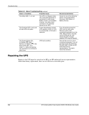
... charging the battery, press and hold the Test/Alarm Reset button for shutdown. Have a qualified electrician check the wiring. continued HP Uninterruptible Power System R3000 XR Models User Guide 5-5 If conditions worsen, the UPS may switch to operate until the condition is ...continued Alarm or Condition Possible Cause The On Battery LED ( ) is red, and there is an audible alarm every 5 seconds. If the condition persists, the input voltage may be replaced. The UPS is an audible alarm every 5 seconds. The Utility LED ( ) is flashing red, and there is ...
... charging the battery, press and hold the Test/Alarm Reset button for shutdown. Have a qualified electrician check the wiring. continued HP Uninterruptible Power System R3000 XR Models User Guide 5-5 If conditions worsen, the UPS may switch to operate until the condition is ...continued Alarm or Condition Possible Cause The On Battery LED ( ) is red, and there is an audible alarm every 5 seconds. If the condition persists, the input voltage may be replaced. The UPS is an audible alarm every 5 seconds. The Utility LED ( ) is flashing red, and there is ...
UPS R3000 XR Models User Guide
Page 45
... is red. Troubleshooting Table 5-3: Alarm Troubleshooting continued Alarm or Condition Possible Cause The Utility LED ( ) is defective. The UPS is red, and all load LEDs are off, and restart the UPS. The Overload LED is in Bypass mode. The General Alarm ( ), On Battery ( ), Bad ...Battery/Low Battery ( ), Site Wiring Fault ( ), and Utility ( ) LEDs are no UPS user-serviceable parts. 5-6 HP Uninterruptible Power System R3000 XR Models User Guide Contact an HP authorized service representative. ...
... is red. Troubleshooting Table 5-3: Alarm Troubleshooting continued Alarm or Condition Possible Cause The Utility LED ( ) is defective. The UPS is red, and all load LEDs are off, and restart the UPS. The Overload LED is in Bypass mode. The General Alarm ( ), On Battery ( ), Bad ...Battery/Low Battery ( ), Site Wiring Fault ( ), and Utility ( ) LEDs are no UPS user-serviceable parts. 5-6 HP Uninterruptible Power System R3000 XR Models User Guide Contact an HP authorized service representative. ...

UPS R3000 XR Models User Guide
Page 61
... telephone numbers viii temperature specifications C-6 Test/Alarm Reset button 2-2 testing batteries 4-5 text conventions vi tools, conductive field service type B-1 troubleshooting after start 5-2 alarm 5-4 during start 5-1 U Utility LED 2-2 V voltage, configuring 3-3 W warnings defined vi warning on testing new batteries 4-5 warranties $25,000 Computer Load Protection Guarantee 1-12 applicability 1-12 limited warranty 1-12 pre-failure...
... telephone numbers viii temperature specifications C-6 Test/Alarm Reset button 2-2 testing batteries 4-5 text conventions vi tools, conductive field service type B-1 troubleshooting after start 5-2 alarm 5-4 during start 5-1 U Utility LED 2-2 V voltage, configuring 3-3 W warnings defined vi warning on testing new batteries 4-5 warranties $25,000 Computer Load Protection Guarantee 1-12 applicability 1-12 limited warranty 1-12 pre-failure...
UPS R1500 XR Models User Guide
Page 20
... Mode - The UPS configuration can be reset). Power is outside the +20% to -30% configured nominal range. Operation continued Item Description 5 Utility LED ( ) 6 Overload LED 7 76% to 100% load 8 51% to 75% load 9 26% to 50% load 10 0% to 25% load 11 Configure Mode On...UPS output receptacles. - Green-Utility voltage is present and output is on, or utility voltage has returned to the voltage range for which the UPS has been configured (UPS is off ). Output is supplying utility power and the audible alarm should be updated. 2-2 HP Uninterruptible Power System R1500 XR...
... Mode - The UPS configuration can be reset). Power is outside the +20% to -30% configured nominal range. Operation continued Item Description 5 Utility LED ( ) 6 Overload LED 7 76% to 100% load 8 51% to 75% load 9 26% to 50% load 10 0% to 25% load 11 Configure Mode On...UPS output receptacles. - Green-Utility voltage is present and output is on, or utility voltage has returned to the voltage range for which the UPS has been configured (UPS is off ). Output is supplying utility power and the audible alarm should be updated. 2-2 HP Uninterruptible Power System R1500 XR...