

HP UPS Best Practices
Page 6
... Provides up to 60-day advanced notification when batteries are approaching the end of useful life Page 6 of 27 HP UPS Models Available Rackmount UPS Model Numbers AF419A R1500 G2 NA AF418A R1500 G2 INTL AF421A R1500 G2 JPN/TWN AF422A R3000 ... Module Serial Adapter - 5 pack R3000 ERM R/T3000 ERM R5500 ERM R5500 Tower Conversion Kit R8000/3 and R12000/3 ERM HP R12000/3 EXPANSION MODULE FOR RP36000/3 NA HP R12000/3 EXPANSION MODULE FOR RP36000/3 INTL HP Rackmount UPS Advantages Designed for dense data-center environments, HP rackmount UPS solutions provide powerful performance while ...
... Provides up to 60-day advanced notification when batteries are approaching the end of useful life Page 6 of 27 HP UPS Models Available Rackmount UPS Model Numbers AF419A R1500 G2 NA AF418A R1500 G2 INTL AF421A R1500 G2 JPN/TWN AF422A R3000 ... Module Serial Adapter - 5 pack R3000 ERM R/T3000 ERM R5500 ERM R5500 Tower Conversion Kit R8000/3 and R12000/3 ERM HP R12000/3 EXPANSION MODULE FOR RP36000/3 NA HP R12000/3 EXPANSION MODULE FOR RP36000/3 INTL HP Rackmount UPS Advantages Designed for dense data-center environments, HP rackmount UPS solutions provide powerful performance while ...

HP UPS Best Practices
Page 7
... single UPS configuration or provides additional power protection with exceptional voltage regulation. http://h18004.www1.hp.com/products/servers/proliantstorage/power-protection/pdu.html Extended Runtime Modules (ERMs) extend runtime and enable work to continue even during prolonged outages Best-in-class Warranty... within 3-year period $250,000 computer load protection guarantee provides additional peace of mind Page 7 of HP UPSs. The HP UPS Management Module can easily happen when running on generator power --- The UPS automatically boosts input utility voltage up ...
... single UPS configuration or provides additional power protection with exceptional voltage regulation. http://h18004.www1.hp.com/products/servers/proliantstorage/power-protection/pdu.html Extended Runtime Modules (ERMs) extend runtime and enable work to continue even during prolonged outages Best-in-class Warranty... within 3-year period $250,000 computer load protection guarantee provides additional peace of mind Page 7 of HP UPSs. The HP UPS Management Module can easily happen when running on generator power --- The UPS automatically boosts input utility voltage up ...

HP UPS Best Practices
Page 8
... of 27 This leading-edge UPS features a spacesaving 2U design that delivers up to be connected to optional Extended Runtime Modules (ERMs), allowing customers to provide key advantages including increased power efficiency and a smaller footprint with less weight. The densest, most power-packed ...than any other UPS, enabling more valuable rack space to 2700 watts of true power for unprecedented power density. HP Rackmount UPS Models HP R1500 G2 Rackmount UPS The HP R1500 G2 UPS is a high power-density solution designed for customers desiring superior power protection in space-constrained ...
... of 27 This leading-edge UPS features a spacesaving 2U design that delivers up to be connected to optional Extended Runtime Modules (ERMs), allowing customers to provide key advantages including increased power efficiency and a smaller footprint with less weight. The densest, most power-packed ...than any other UPS, enabling more valuable rack space to 2700 watts of true power for unprecedented power density. HP Rackmount UPS Models HP R1500 G2 Rackmount UPS The HP R1500 G2 UPS is a high power-density solution designed for customers desiring superior power protection in space-constrained ...

HP UPS Best Practices
Page 10
...with Enhanced Battery Management (EBM); Page 10 of power protection. HP R5500 Rackmount UPS The R5500 UPS provides more power protection per U than any other HP UPS, and supports any rackmount server application requiring up to 4 ERMs with FW version 2.08 or higher); and easy serviceability with ...hot-swappable electronics and batteries. With two load segments and free HP power management software, it is easy ...
...with Enhanced Battery Management (EBM); Page 10 of power protection. HP R5500 Rackmount UPS The R5500 UPS provides more power protection per U than any other HP UPS, and supports any rackmount server application requiring up to 4 ERMs with FW version 2.08 or higher); and easy serviceability with ...hot-swappable electronics and batteries. With two load segments and free HP power management software, it is easy ...

HP UPS Best Practices
Page 14
Run Time per HP UPS Model Backup times** (in minutes) T750 G2 and T750 Japan Load, percent 50% 100% Load, Watts 250 500 T1000 G3 and T1000 Japan Load, ... 100% battery charge 15 minutes 5 minutes With 1 ERM 120 minutes 45 minutes 30 minutes 20 minutes With 2 ERMs 250 minutes 100 minutes 60 minutes 40 minutes With 1 ERM 142 minutes 55 minutes 34 minutes 26 minutes With 2 ERMs 256 minutes 99 minutes 60 minutes 47 minutes With 1 ERM 125 minutes 50 minutes 30 minutes 24...
Run Time per HP UPS Model Backup times** (in minutes) T750 G2 and T750 Japan Load, percent 50% 100% Load, Watts 250 500 T1000 G3 and T1000 Japan Load, ... 100% battery charge 15 minutes 5 minutes With 1 ERM 120 minutes 45 minutes 30 minutes 20 minutes With 2 ERMs 250 minutes 100 minutes 60 minutes 40 minutes With 1 ERM 142 minutes 55 minutes 34 minutes 26 minutes With 2 ERMs 256 minutes 99 minutes 60 minutes 47 minutes With 1 ERM 125 minutes 50 minutes 30 minutes 24...

HP UPS Best Practices
Page 15
... 143 minutes 120 minutes 87 minutes 76 minutes 69 minutes 60 minutes Load per R8000/3 kW % 1.6 20% 2.4 30% 4 50% 6 75% 8 100% Battery Runtime Chart Internal +1 ERM +2 ERM +3 ERM +4 ERM 55 118 183 253 329 37 78 119 163 211 23 46 69 94 120 13 30 44 59 76 9 21 32 43 54 Load... per R12000/3 UPS kW % 1.6 13% 2.4 20% 4 33% 6 50% 8 67% 9.6 80% 12 100% Battery Runtime Chart Internal +1 ERM +2 ERM +3 ERM +4 ERM 55 118 183 253 329 37 78 119 163 211 23 46 69 94 120 13 30 44 59 76 9 21 32 43 54 6.9 17...
... 143 minutes 120 minutes 87 minutes 76 minutes 69 minutes 60 minutes Load per R8000/3 kW % 1.6 20% 2.4 30% 4 50% 6 75% 8 100% Battery Runtime Chart Internal +1 ERM +2 ERM +3 ERM +4 ERM 55 118 183 253 329 37 78 119 163 211 23 46 69 94 120 13 30 44 59 76 9 21 32 43 54 Load... per R12000/3 UPS kW % 1.6 13% 2.4 20% 4 33% 6 50% 8 67% 9.6 80% 12 100% Battery Runtime Chart Internal +1 ERM +2 ERM +3 ERM +4 ERM 55 118 183 253 329 37 78 119 163 211 23 46 69 94 120 13 30 44 59 76 9 21 32 43 54 6.9 17...

HP UPS Best Practices
Page 18
...is not completed, the ERM will shut down the load. 5. The purpose of this process is turned off, usually within 72 hours of the beginning of each time it represent the results of 27 Configuring the HP software for at http://h18004.www1.hp.com/products/servers/platforms/...to 100% with its configured operating system (OS) and subsequent attached storage has a required time for shutdown, which one must consider the run a ERM configuration utility that the load will still provide backup time to shut down a system. Therefore, in each UPS. 6. Every server with older batteries...
...is not completed, the ERM will shut down the load. 5. The purpose of this process is turned off, usually within 72 hours of the beginning of each time it represent the results of 27 Configuring the HP software for at http://h18004.www1.hp.com/products/servers/platforms/...to 100% with its configured operating system (OS) and subsequent attached storage has a required time for shutdown, which one must consider the run a ERM configuration utility that the load will still provide backup time to shut down a system. Therefore, in each UPS. 6. Every server with older batteries...

HP UPS R3000 User Guide
Page 3
... front panel controls ...7 UPS front panel LED indicators...8 HP UPS R3000 models ...8 UPS R3000 NA and R3000j JPN rear panel 9 UPS R3000h NA and R3000h JPN rear panel 10 UPS R3000 INT rear panel ...11 REPO port ...11 ERM rear panel...12 Installation ...13 Precautions ...13 Preparing to...batteries ...24 Starting power to the load...24 Installing the ERM...24 Attaching the ERM front bezel ...25 Switching off the ERM circuit breaker 25 Connecting the ERM to the UPS ...25 Switching on the ERM circuit breaker 26 Charging the ERM batteries...26 UPS operations...27 Modes of operation...27 Standby...
... front panel controls ...7 UPS front panel LED indicators...8 HP UPS R3000 models ...8 UPS R3000 NA and R3000j JPN rear panel 9 UPS R3000h NA and R3000h JPN rear panel 10 UPS R3000 INT rear panel ...11 REPO port ...11 ERM rear panel...12 Installation ...13 Precautions ...13 Preparing to...batteries ...24 Starting power to the load...24 Installing the ERM...24 Attaching the ERM front bezel ...25 Switching off the ERM circuit breaker 25 Connecting the ERM to the UPS ...25 Switching on the ERM circuit breaker 26 Charging the ERM batteries...26 UPS operations...27 Modes of operation...27 Standby...

HP UPS R3000 User Guide
Page 4
...Powering down the UPS...31 Power management ...32 Power management software...32 Maintenance ...33 Removing the UPS front bezel ...33 Removing the ERM front bezel ...33 Replacing the UPS electronics module ...33 Replacing the UPS option card ...34 Replacing the batteries ...35 Important battery safety... 36 Obtaining new batteries ...36 UPS battery replacement procedure 36 Testing the new battery module...38 Replacing the UPS ...38 Replacing the ERM ...38 Updating the UPS firmware ...39 Configuring a USB to serial converter 39 Reassigning the USB COM ports...40 Troubleshooting ...41 LED...
...Powering down the UPS...31 Power management ...32 Power management software...32 Maintenance ...33 Removing the UPS front bezel ...33 Removing the ERM front bezel ...33 Replacing the UPS electronics module ...33 Replacing the UPS option card ...34 Replacing the batteries ...35 Important battery safety... 36 Obtaining new batteries ...36 UPS battery replacement procedure 36 Testing the new battery module...38 Replacing the UPS ...38 Replacing the ERM ...38 Updating the UPS firmware ...39 Configuring a USB to serial converter 39 Reassigning the USB COM ports...40 Troubleshooting ...41 LED...

HP UPS R3000 User Guide
Page 5
REPO port specifications ...49 Spares...50 Ordering spares...50 UPS spare parts list...50 ERM spare parts list ...51 Hardware options ...51 Technical support...52 Before you contact HP ...52 HP contact information...52 Warranty information...53 Limited warranty ...53 $250,000 Computer Load Protection Guarantee 53 Pre-Failure Battery Warranty...53 Recommended duration...
REPO port specifications ...49 Spares...50 Ordering spares...50 UPS spare parts list...50 ERM spare parts list ...51 Hardware options ...51 Technical support...52 Before you contact HP ...52 HP contact information...52 Warranty information...53 Limited warranty ...53 $250,000 Computer Load Protection Guarantee 53 Pre-Failure Battery Warranty...53 Recommended duration...
HP UPS R3000 User Guide
Page 10
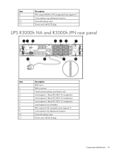
... attachment locations Ground bonding screw Power cord with L5-30 plug UPS R3000h NA and R3000h JPN rear panel Item 1 2 3 4 5 6 7 8 9 10 11 Description REPO port ERM connector Serial communications port/options slot Load segment 1 (three IEC-320-C13 receptacles) Load segment 2 (three IEC-320-C13 receptacles) Load segment 3 (three IEC-320...
... attachment locations Ground bonding screw Power cord with L5-30 plug UPS R3000h NA and R3000h JPN rear panel Item 1 2 3 4 5 6 7 8 9 10 11 Description REPO port ERM connector Serial communications port/options slot Load segment 1 (three IEC-320-C13 receptacles) Load segment 2 (three IEC-320-C13 receptacles) Load segment 3 (three IEC-320...

HP UPS R3000 User Guide
Page 11
UPS R3000 INT rear panel Item 1 2 3 4 5 6 7 8 9 10 11 Description REPO port ERM connector Serial communications port/options slot Load segment 1 (three IEC-320-C13 receptacles) Load segment 2 (three IEC-320-C13 receptacles) Load segment 3 (three IEC-320-...
UPS R3000 INT rear panel Item 1 2 3 4 5 6 7 8 9 10 11 Description REPO port ERM connector Serial communications port/options slot Load segment 1 (three IEC-320-C13 receptacles) Load segment 2 (three IEC-320-C13 receptacles) Load segment 3 (three IEC-320-...

HP UPS R3000 User Guide
Page 12
...without utility present normally initiates a battery start is inhibited and the UPS is not able to assume the load. ERM rear panel Item 1 2 3 Description ERM input connector (from another ERM output) Circuit breaker ERM output connector (to the UPS. However, if the On button is pressed and a REPO is detected, battery ... the load devices after the REPO feature is activated, press the On button after the AC source is reconnected to the UPS or another ERM) Component identification 12 NOTE: If the UPS was operating on battery power when the remote switch was closed, no power is available to ...
...without utility present normally initiates a battery start is inhibited and the UPS is not able to assume the load. ERM rear panel Item 1 2 3 Description ERM input connector (from another ERM output) Circuit breaker ERM output connector (to the UPS. However, if the On button is pressed and a REPO is detected, battery ... the load devices after the REPO feature is activated, press the On button after the AC source is reconnected to the UPS or another ERM) Component identification 12 NOTE: If the UPS was operating on battery power when the remote switch was closed, no power is available to ...

HP UPS R3000 User Guide
Page 13
... lb This symbol indicates that the UPS exceeds the recommended weight for one individual to handle safely. This document contains important safety instructions that the ERM exceeds the recommended weight for one individual to handle safely. WARNING: A risk of personal injury or damage to install the hardware Before installing the hardware...
... lb This symbol indicates that the UPS exceeds the recommended weight for one individual to handle safely. This document contains important safety instructions that the ERM exceeds the recommended weight for one individual to handle safely. WARNING: A risk of personal injury or damage to install the hardware Before installing the hardware...
HP UPS R3000 User Guide
Page 24
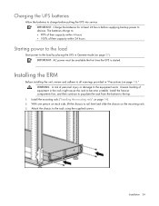
... before supplying backup power to the load by placing the UPS in Operate mode (on page 27). With one person on page 13)." Installing the ERM Before installing the unit, review and adhere to the top. 1. Install the heavier components first, and then continue to populate the rack from the bottom...
... before supplying backup power to the load by placing the UPS in Operate mode (on page 27). With one person on page 13)." Installing the ERM Before installing the unit, review and adhere to the top. 1. Install the heavier components first, and then continue to populate the rack from the bottom...
HP UPS R3000 User Guide
Page 25
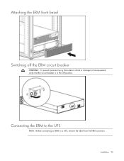
Installation 25 Attaching the ERM front bezel Switching off the ERM circuit breaker WARNING: To prevent personal injury from the ERM connector. Connecting the ERM to the UPS NOTE: Before connecting an ERM to a UPS, remove the label from electric shock or damage to the equipment, verify that the circuit breaker is in the Off position.
Installation 25 Attaching the ERM front bezel Switching off the ERM circuit breaker WARNING: To prevent personal injury from the ERM connector. Connecting the ERM to the UPS NOTE: Before connecting an ERM to a UPS, remove the label from electric shock or damage to the equipment, verify that the circuit breaker is in the Off position.
HP UPS R3000 User Guide
Page 26
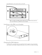
When the UPS is plugged in the socket (2) at the rear of the UPS. Allow 24 hours for the ERM to two ERM units can be connected. NOTE: To install a second ERM, plug the cable from the second ERM into the socket at the rear of the first ERM. Up to fully charge. Switching on the ERM circuit breaker Charging the ERM batteries Connect the UPS to a grounded utility power outlet. Installation 26 Plug the ERM cable (1) in , the unit automatically enters Standby mode and begins charging the ERM batteries.
When the UPS is plugged in the socket (2) at the rear of the UPS. Allow 24 hours for the ERM to two ERM units can be connected. NOTE: To install a second ERM, plug the cable from the second ERM into the socket at the rear of the first ERM. Up to fully charge. Switching on the ERM circuit breaker Charging the ERM batteries Connect the UPS to a grounded utility power outlet. Installation 26 Plug the ERM cable (1) in , the unit automatically enters Standby mode and begins charging the ERM batteries.
HP UPS R3000 User Guide
Page 28
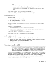
... page 28), and use the ERM configurator tool. After the ERMs are installed, place the UPS in Configure mode (on page 7)." Remove the front bezel ("Removing the UPS front bezel" on page 8)." For the location of buttons, see the HP website (http://www.hp.com/go/rackandpower). In Configure...charges the batteries as necessary. • The UPS configuration can be configured are illuminated), press the On button to enable modification of attached ERMs. Other UPS parameters that can also be placed in Configure mode while in Configure mode: 1. Configure mode In Configure mode: • ...
... page 28), and use the ERM configurator tool. After the ERMs are installed, place the UPS in Configure mode (on page 7)." Remove the front bezel ("Removing the UPS front bezel" on page 8)." For the location of buttons, see the HP website (http://www.hp.com/go/rackandpower). In Configure...charges the batteries as necessary. • The UPS configuration can be configured are illuminated), press the On button to enable modification of attached ERMs. Other UPS parameters that can also be placed in Configure mode while in Configure mode: 1. Configure mode In Configure mode: • ...

HP UPS R3000 User Guide
Page 29
... input voltage parameter turns off and the LED associated with the currently configured parameters illuminate. This parameter is configured for 2 attached ERMs NOTE: For units factory-configured for 200 V or 208 V, the Site Wiring Fault function has been disabled. A flashing green...neutral connections are in Configure mode. When setting voltage configuration parameters, selecting an On value for line-to select the appropriate ERM configuration. Enabling this feature for any one nominal utility voltage can be configured. NOTE: Only one parameter automatically sets the other...
... input voltage parameter turns off and the LED associated with the currently configured parameters illuminate. This parameter is configured for 2 attached ERMs NOTE: For units factory-configured for 200 V or 208 V, the Site Wiring Fault function has been disabled. A flashing green...neutral connections are in Configure mode. When setting voltage configuration parameters, selecting an On value for line-to select the appropriate ERM configuration. Enabling this feature for any one nominal utility voltage can be configured. NOTE: Only one parameter automatically sets the other...
HP UPS R3000 User Guide
Page 33
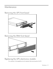
Maintenance Removing the UPS front bezel Removing the ERM front bezel Replacing the UPS electronics module This component is hot-swappable and can be replaced without powering down the UPS. Maintenance 33
Maintenance Removing the UPS front bezel Removing the ERM front bezel Replacing the UPS electronics module This component is hot-swappable and can be replaced without powering down the UPS. Maintenance 33