
Service Guide
Page 5
... description ...1 2 External component identification ...9 Display ...9 Top ...10 TouchPad ...10 Lights ...11 Buttons and fingerprint reader (select models only 12 Keys ...14 Front ...16 Left ...17 Right ...18 Bottom ...19 3 Illustrated parts catalog ...20 Service tag ...20 Computer major components ...21 Display components ...29 Plastics Kit ...31 Cable Kit ...32 Mass storage devices ...32 Miscellaneous parts ...33 Sequential part number listing ...34 4 Removal and replacement procedures ...42 Preliminary replacement requirements 42...
... description ...1 2 External component identification ...9 Display ...9 Top ...10 TouchPad ...10 Lights ...11 Buttons and fingerprint reader (select models only 12 Keys ...14 Front ...16 Left ...17 Right ...18 Bottom ...19 3 Illustrated parts catalog ...20 Service tag ...20 Computer major components ...21 Display components ...29 Plastics Kit ...31 Cable Kit ...32 Mass storage devices ...32 Miscellaneous parts ...33 Sequential part number listing ...34 4 Removal and replacement procedures ...42 Preliminary replacement requirements 42...
Service Guide
Page 6
... WLAN/Bluetooth combo card 59 Keyboard ...64 Fan ...67 Heat sink ...69 Processor ...71 Top cover ...72 RTC battery ...79 Modem module ...81 Audio board ...83 Speaker assembly ...84 RJ-11 jack cable ...87 Quick Launch board ...89 USB board ...92 System board ...93 Card reader board ...97 Power cable ...99 Optical drive connector ...101 Display assembly ...103 5 Computer Setup (BIOS) and System Diagnostics 111 Using Computer Setup ...111 Starting Computer Setup 111 Navigating and selecting in Computer Setup 111 Restoring factory settings...
... WLAN/Bluetooth combo card 59 Keyboard ...64 Fan ...67 Heat sink ...69 Processor ...71 Top cover ...72 RTC battery ...79 Modem module ...81 Audio board ...83 Speaker assembly ...84 RJ-11 jack cable ...87 Quick Launch board ...89 USB board ...92 System board ...93 Card reader board ...97 Power cable ...99 Optical drive connector ...101 Display assembly ...103 5 Computer Setup (BIOS) and System Diagnostics 111 Using Computer Setup ...111 Starting Computer Setup 111 Navigating and selecting in Computer Setup 111 Restoring factory settings...
Service Guide
Page 13
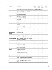
... area network (PAN) options by way of Bluetooth® module: Bluetooth 3.0 only supported by combo card √ √ √ External media card One ExpressCard 34mm slot √ √ √ 6-in-1 Digital Media Reader Slot √ √ √ Ports Audio-in (stereo microphone) √ √ √ Audio-out (stereo headphone) √ √ √ RJ-11 (modem) √ √ √ RJ-45 (Ethernet, includes link and activity lights) √ √ √ USB 3.0 (1) √...
... area network (PAN) options by way of Bluetooth® module: Bluetooth 3.0 only supported by combo card √ √ √ External media card One ExpressCard 34mm slot √ √ √ 6-in-1 Digital Media Reader Slot √ √ √ Ports Audio-in (stereo microphone) √ √ √ Audio-out (stereo headphone) √ √ √ RJ-11 (modem) √ √ √ RJ-45 (Ethernet, includes link and activity lights) √ √ √ USB 3.0 (1) √...
Service Guide
Page 23
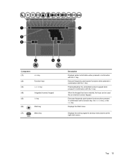
... been enabled, the keys can be used system functions when pressed in combination with the fn key. Displays the active program's shortcut menu (same as the right-click menu).. Top 15 Displays the Start menu. Executes frequently used like an external numeric keypad. Enables/disables the embedded numeric keypad when pressed in combination with the fn key. Component (1) esc key (2) Function keys (3) num lk key (4) Integrated numeric keypad (5) fn key (6) Start key (7) Menu key Description Displays system...
... been enabled, the keys can be used system functions when pressed in combination with the fn key. Displays the active program's shortcut menu (same as the right-click menu).. Top 15 Displays the Start menu. Executes frequently used like an external numeric keypad. Enables/disables the embedded numeric keypad when pressed in combination with the fn key. Component (1) esc key (2) Function keys (3) num lk key (4) Integrated numeric keypad (5) fn key (6) Start key (7) Menu key Description Displays system...
Service Guide
Page 25
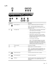
... or audio component. Connects an AC adapter. NOTE: The computer fan starts up automatically to 90% charged. ● Blinking amber: A battery that is normal for the internal fan to the computer. Left Component (1) Security cable slot (2) AC adapter light (3) Power connector (4) Vent (5) External monitor port (6) RJ-45 (network) jack (7) HDMI port Description Attaches an optional security cable to cycle on and off during routine operation. Connects an external VGA monitor or projector. Connects a network cable. It is the only available power source...
... or audio component. Connects an AC adapter. NOTE: The computer fan starts up automatically to 90% charged. ● Blinking amber: A battery that is normal for the internal fan to the computer. Left Component (1) Security cable slot (2) AC adapter light (3) Power connector (4) Vent (5) External monitor port (6) RJ-45 (network) jack (7) HDMI port Description Attaches an optional security cable to cycle on and off during routine operation. Connects an external VGA monitor or projector. Connects a network cable. It is the only available power source...
Service Guide
Page 28
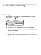
...; Serial number (s/n) (2). This number provides specific information about the product's hardware components. This is the product name affixed to locate documents, drivers, and support for the computer. ● Model description (5). This is the alphanumeric identifier used to the front of the warranty period for the computer. 20 Chapter 3 Illustrated parts catalog 3 Illustrated parts catalog Service tag When ordering parts or requesting information, provide the computer serial number...
...; Serial number (s/n) (2). This number provides specific information about the product's hardware components. This is the product name affixed to locate documents, drivers, and support for the computer. ● Model description (5). This is the alphanumeric identifier used to the front of the warranty period for the computer. 20 Chapter 3 Illustrated parts catalog 3 Illustrated parts catalog Service tag When ordering parts or requesting information, provide the computer serial number...
Service Guide
Page 55
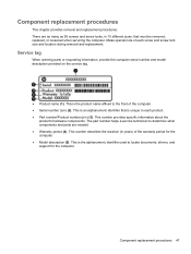
... needed. ● Warranty period (4). Service tag When ordering parts or requesting information, provide the computer serial number and model description provided on the service tag. ● Product name (1). This number provides specific information about the product's hardware components. This is unique to the front of each product. ● Part number/Product number (p/n) (3). Make special note of the computer. ● Serial number (s/n) (2). The part number helps a service technician to locate documents, drivers, and support...
... needed. ● Warranty period (4). Service tag When ordering parts or requesting information, provide the computer serial number and model description provided on the service tag. ● Product name (1). This number provides specific information about the product's hardware components. This is unique to the front of each product. ● Part number/Product number (p/n) (3). Make special note of the computer. ● Serial number (s/n) (2). The part number helps a service technician to locate documents, drivers, and support...
Service Guide
Page 57
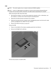
... power cord from the AC outlet, and then unplugging the AC adapter from the SIM slot. Shut down through the operating system. 2. If you are unsure whether the computer is a SIM inserted in Hibernation, turn the computer on, and then shut it must be removed before disassembling the computer. Remove the SIM: 1. Component replacement procedures 49 Disconnect all external devices connected to install...
... power cord from the AC outlet, and then unplugging the AC adapter from the SIM slot. Shut down through the operating system. 2. If you are unsure whether the computer is a SIM inserted in Hibernation, turn the computer on, and then shut it must be removed before disassembling the computer. Remove the SIM: 1. Component replacement procedures 49 Disconnect all external devices connected to install...
Service Guide
Page 63
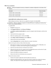
... 621569-001 Update BIOS before adding memory modules Before adding new memory, make sure you are unsure whether the computer is installed in a stacked configuration in various system problems. To update BIOS: 1. In the Enter a product name/number box, type the computer model information, and then click Search. 4. Under Step 2: Select a Download, click the BIOS link. 7. Disconnect all external devices connected to www.hp.com. 2. Remove the bottom door (see Battery on -screen instructions. Position the...
... 621569-001 Update BIOS before adding memory modules Before adding new memory, make sure you are unsure whether the computer is installed in a stacked configuration in various system problems. To update BIOS: 1. In the Enter a product name/number box, type the computer model information, and then click Search. 4. Under Step 2: Select a Download, click the BIOS link. 7. Disconnect all external devices connected to www.hp.com. 2. Remove the bottom door (see Battery on -screen instructions. Position the...
Service Guide
Page 119
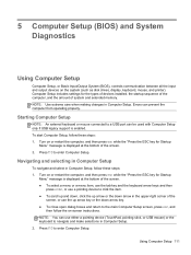
... press esc while the "Press the ESC key for the types of devices installed, the startup sequence of the computer, and the amount of system and extended memory. Starting Computer Setup NOTE: An external keyboard or mouse connected to enter Computer Setup. Press f10 to a USB port can be used with Computer Setup only if USB legacy support is enabled. Navigating and selecting in Computer Setup To navigate and select in Computer...
... press esc while the "Press the ESC key for the types of devices installed, the startup sequence of the computer, and the amount of system and extended memory. Starting Computer Setup NOTE: An external keyboard or mouse connected to enter Computer Setup. Press f10 to a USB port can be used with Computer Setup only if USB legacy support is enabled. Navigating and selecting in Computer Setup To navigate and select in Computer...
Service Guide
Page 120
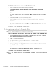
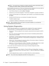
... Computer Setup NOTE: Restoring defaults will not change the hard drive mode. Use the tab key and the arrow keys to select File > Save Changes and Exit, and then press enter. Your changes go into effect when the computer restarts. Follow the on-screen instructions. 5. Use the arrow keys to select File > Save Changes and Exit, and then press enter. NOTE: Your password settings and security settings are not changed when you restore the factory settings...
... Computer Setup NOTE: Restoring defaults will not change the hard drive mode. Use the tab key and the arrow keys to select File > Save Changes and Exit, and then press enter. Your changes go into effect when the computer restarts. Follow the on-screen instructions. 5. Use the arrow keys to select File > Save Changes and Exit, and then press enter. NOTE: Your password settings and security settings are not changed when you restore the factory settings...
Service Guide
Page 121
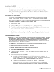
..., follow these instructions: Do not disconnect power from the AC outlet. Make a note of the path to the location on the HP Web site are ready to download. 3. You will need to access this information to locate the update later, after it has been downloaded to your hard drive where the BIOS update is connected to reliable external power using Computer Setup. 1. Start Computer Setup. 2. BIOS version information (also known as ROM date and...
..., follow these instructions: Do not disconnect power from the AC outlet. Make a note of the path to the location on the HP Web site are ready to download. 3. You will need to access this information to locate the update later, after it has been downloaded to your hard drive where the BIOS update is connected to reliable external power using Computer Setup. 1. Start Computer Setup. 2. BIOS version information (also known as ROM date and...
Service Guide
Page 122
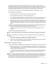
.... If no instructions are required to a network, consult the network administrator before installing any instructions that are displayed, follow the on your hard drive. Turn on the screen after the download is running, press esc. 114 Chapter 5 Computer Setup (BIOS) and System Diagnostics Click the diagnostic test you need to report the issue and purchase a replacement battery. Follow any software updates, especially system BIOS updates. Complete the installation by selecting Start > Computer...
.... If no instructions are required to a network, consult the network administrator before installing any instructions that are displayed, follow the on your hard drive. Turn on the screen after the download is running, press esc. 114 Chapter 5 Computer Setup (BIOS) and System Diagnostics Click the diagnostic test you need to report the issue and purchase a replacement battery. Follow any software updates, especially system BIOS updates. Complete the installation by selecting Start > Computer...
Service Guide
Page 133
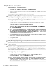
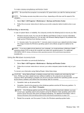
... Start > All Programs > Maintenance > Backup and Restore. 2. Follow the on the type of optical drive installed in your computer or the type of external optical drive you use will depend on -screen instructions to set up your backup, create a system image (select models only), or create a system repair disc (select models only). The image includes the Windows operating system and software programs installed at the factory. NOTE: If you are using. For additional information, refer to Using a Windows 7 operating system DVD...
... Start > All Programs > Maintenance > Backup and Restore. 2. Follow the on the type of optical drive installed in your computer or the type of external optical drive you use will depend on -screen instructions to set up your backup, create a system image (select models only), or create a system repair disc (select models only). The image includes the Windows operating system and software programs installed at the factory. NOTE: If you are using. For additional information, refer to Using a Windows 7 operating system DVD...
Service Guide
Page 134
... drivers, software, and utilities from the backup used for the HP Recovery partition, click Start, right-click Computer, click Manage, and then click Disk Management. Select Startup Repair. 5. To recover your files. For additional information, refer to Using a Windows 7 operating system DVD (purchased separately) on page 127. 126 Chapter 7 Backup and recovery Select Start > All Programs > Maintenance > Backup and Restore. 2. NOTE: If the Windows partition and the HP Recovery partition are permanently removed. Follow the on -screen instructions. Follow the on -screen instructions...
... drivers, software, and utilities from the backup used for the HP Recovery partition, click Start, right-click Computer, click Manage, and then click Disk Management. Select Startup Repair. 5. To recover your files. For additional information, refer to Using a Windows 7 operating system DVD (purchased separately) on page 127. 126 Chapter 7 Backup and recovery Select Start > All Programs > Maintenance > Backup and Restore. 2. NOTE: If the Windows partition and the HP Recovery partition are permanently removed. Follow the on -screen instructions. Follow the on -screen instructions...
Service Guide
Page 136
... optical drive of the computer. 128 Chapter 7 Backup and recovery As you add new software and data files, you should create your initial backup immediately after a system failure is as complete as installing software, running utilities, or changing Windows settings. The screen shot can be prompted for your permission or password for later use. Refer to discs, use any of the following when backing up your information Recovery after software setup...
... optical drive of the computer. 128 Chapter 7 Backup and recovery As you add new software and data files, you should create your initial backup immediately after a system failure is as complete as installing software, running utilities, or changing Windows settings. The screen shot can be prompted for your permission or password for later use. Refer to discs, use any of the following when backing up your information Recovery after software setup...
Service Guide
Page 137
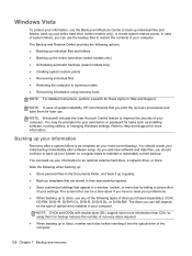
... HP Recovery partition have been deleted, you have created and any software installed on -screen instructions to AC power before the Windows operating system loads. When reformatting is connected to recover your entire computer (select models only) or your information using the Windows Vista operating system DVD and the Driver Recovery disc (both purchased separately). The image includes the Windows operating system and software programs installed at the factory. Select Start > All Programs > Maintenance > Backup and Restore Center. 2. You can also use Windows Startup Repair...
... HP Recovery partition have been deleted, you have created and any software installed on -screen instructions to AC power before the Windows operating system loads. When reformatting is connected to recover your entire computer (select models only) or your information using the Windows Vista operating system DVD and the Driver Recovery disc (both purchased separately). The image includes the Windows operating system and software programs installed at the factory. Select Start > All Programs > Maintenance > Backup and Restore Center. 2. You can also use Windows Startup Repair...
Service Guide
Page 148
... TouchPad on/off 10 wireless 13 C Cable Kit contents 32 spare part number 32, 39 cables, service considerations 43 caps lock light, identifying 11 card reader board removal 97 spare part number 22, 38, 97 chipset, product description 2 components bottom 19 display 9 front 16 left side 17 right side 18 top 10 Computer Setup navigating and selecting 111 restoring factory settings 112 computer specifications 115 connectors, service considerations 43 D diskette drive precautions 43 display...
... TouchPad on/off 10 wireless 13 C Cable Kit contents 32 spare part number 32, 39 cables, service considerations 43 caps lock light, identifying 11 card reader board removal 97 spare part number 22, 38, 97 chipset, product description 2 components bottom 19 display 9 front 16 left side 17 right side 18 top 10 Computer Setup navigating and selecting 111 restoring factory settings 112 computer specifications 115 connectors, service considerations 43 D diskette drive precautions 43 display...
Service Guide
Page 149
... lk 14, 15 start 14, 15 L legacy support, USB 111 lights AC adapter 17 caps lock 11 drive 16 optical drive 18 power 11 QuickWeb 11 TouchPad 11 webcam 9 wireless 11 M mass storage devices, spare part numbers 32 Media Card Reader 16 memory module product description 2 removal 55 spare part numbers 27, 55 menu key, identifying 14, 15 microphone (audio-in) jack product description 4 microphone module spare part number 38 model name 1 modem module product description 4 removal 81 spare part number 26, 35, 81 N network jack, identifying 17 num...
... lk 14, 15 start 14, 15 L legacy support, USB 111 lights AC adapter 17 caps lock 11 drive 16 optical drive 18 power 11 QuickWeb 11 TouchPad 11 webcam 9 wireless 11 M mass storage devices, spare part numbers 32 Media Card Reader 16 memory module product description 2 removal 55 spare part numbers 27, 55 menu key, identifying 14, 15 microphone (audio-in) jack product description 4 microphone module spare part number 38 model name 1 modem module product description 4 removal 81 spare part number 26, 35, 81 N network jack, identifying 17 num...
Service Guide
Page 150
... part numbers 26, 71 product description audio 4 chipset 2 display panel 2 Ethernet 4 external media cards 5 graphics 2 hard drives 3 keyboard 5 memory module 2 microphone 4 modem module 4 operating system 5 optical drives 3 pointing devices 5 ports 5 power requirements 5 processors 1 product name 1 security 5 serviceability 7 webcam 4 wireless 4 product name 1 Q Quick Launch board removal 89 spare part number 23, 38 spare part numbers 89 QuickWeb button, identifying 13 QuickWeb light 11 R recovery partition 126, 130 release latches access cover 19 battery 19 removal/replacement preliminaries...
... part numbers 26, 71 product description audio 4 chipset 2 display panel 2 Ethernet 4 external media cards 5 graphics 2 hard drives 3 keyboard 5 memory module 2 microphone 4 modem module 4 operating system 5 optical drives 3 pointing devices 5 ports 5 power requirements 5 processors 1 product name 1 security 5 serviceability 7 webcam 4 wireless 4 product name 1 Q Quick Launch board removal 89 spare part number 23, 38 spare part numbers 89 QuickWeb button, identifying 13 QuickWeb light 11 R recovery partition 126, 130 release latches access cover 19 battery 19 removal/replacement preliminaries...


