User Manual
Page 2
... FEATURES 2 BEFORE USE 2 Contents of Package 2 Part Names 3 Loading the Batteries 5 INSTALLATION 6 Installation of the Projector and Screen........6 Angle Adjustment 6 Cabling 7 Power Connection 8 Example of this liquid crystal projector. Basic Operations 10 Table 4. Specifications 23 For "TECHNICAL" and "REGULATORY NOTICE", see the end of System Setup 8 Plug & Play 8 OPERATIONS 9 Power ON 9 Power OFF 9 Basic Operation 10 Setup Menu 12 Input Menu 13 Image Menu 14 Options Menu 15 No Signal Menu 16 MAINTENANCE 17 Lamp 17 Air Filter 19 Other...
... FEATURES 2 BEFORE USE 2 Contents of Package 2 Part Names 3 Loading the Batteries 5 INSTALLATION 6 Installation of the Projector and Screen........6 Angle Adjustment 6 Cabling 7 Power Connection 8 Example of this liquid crystal projector. Basic Operations 10 Table 4. Specifications 23 For "TECHNICAL" and "REGULATORY NOTICE", see the end of System Setup 8 Plug & Play 8 OPERATIONS 9 Power ON 9 Power OFF 9 Basic Operation 10 Setup Menu 12 Input Menu 13 Image Menu 14 Options Menu 15 No Signal Menu 16 MAINTENANCE 17 Lamp 17 Air Filter 19 Other...

User Manual
Page 3
... atentamente este manual do usuário. Projector Liquid Crystal Projector CP-X430W USER'S MANUAL Please read this manual) Safety Instructions Carrying Bag ENGLISH-2 TECHNICAL PORTGÊS NORSK NEDERLANDS ESPAÑOL ITALIANO FRANÇAIS DEUTSCH ENGLISH Power Cord (US Type) Power Cord (UK Type) Power Cord (Europe Type) RGB Cable Lens Cap Component Video Cable (with green lead) Mouse cable (PS/2) STANDBY/ON BLANK LASER VIDEO RGB Batteries for closer viewing. GEBRUIKSAANWIJIZNG...
... atentamente este manual do usuário. Projector Liquid Crystal Projector CP-X430W USER'S MANUAL Please read this manual) Safety Instructions Carrying Bag ENGLISH-2 TECHNICAL PORTGÊS NORSK NEDERLANDS ESPAÑOL ITALIANO FRANÇAIS DEUTSCH ENGLISH Power Cord (US Type) Power Cord (UK Type) Power Cord (Europe Type) RGB Cable Lens Cap Component Video Cable (with green lead) Mouse cable (PS/2) STANDBY/ON BLANK LASER VIDEO RGB Batteries for closer viewing. GEBRUIKSAANWIJIZNG...

User Manual
Page 4
ENGLISH BEFORE USE (continued) Part Names Speaker Carrying Handle AC Inlet (to the Power Cord) Power Switch Foot Adjuster Ventilation Openings (Intake) Zoom Knob Focus Ring Remote Control Sensor Lens Foot Adjuster Lens Cap FRONT/LEFT VIEW OF THE PROJECTOR Control Panel (Refer to P.9 "OPERATIONS") STANDBY/ON Button KEYSTONE Button Foot Adjuster Button Filter Cover ( ) Air Filter and Intake for the Cooling Fan INPUT Button LAMP Indicator TEMP Indicator POWER Indicator RESET Button MENU Button Ventilation Openings (exhaust) REAR/RIGHT VIEW OF THE PROJECTOR S-VIDEO Terminal COMPONENT ...
ENGLISH BEFORE USE (continued) Part Names Speaker Carrying Handle AC Inlet (to the Power Cord) Power Switch Foot Adjuster Ventilation Openings (Intake) Zoom Knob Focus Ring Remote Control Sensor Lens Foot Adjuster Lens Cap FRONT/LEFT VIEW OF THE PROJECTOR Control Panel (Refer to P.9 "OPERATIONS") STANDBY/ON Button KEYSTONE Button Foot Adjuster Button Filter Cover ( ) Air Filter and Intake for the Cooling Fan INPUT Button LAMP Indicator TEMP Indicator POWER Indicator RESET Button MENU Button Ventilation Openings (exhaust) REAR/RIGHT VIEW OF THE PROJECTOR S-VIDEO Terminal COMPONENT ...

User Manual
Page 5
... of procedures other people. WARNING • The laser pointer of the projector. • Do not disassemble the remote control transmitter. ENGLISH-4 POSITION Button MAGNIFY Button AUTO KEYSTONE MENU MENU SELECT RESET POSITION FREEZE PinP MUTE MAGNIFY OFF VOLUME RESET Button Used to click the right mouse button. AUTO Button BLANK STANDBY/ON LASER RGB VIDEO BLANK Button LASER Button RGB Button MOUSE / RIGHT Button Used to click the right mouse button. Remember, the POSITION, BLANK...
... of procedures other people. WARNING • The laser pointer of the projector. • Do not disassemble the remote control transmitter. ENGLISH-4 POSITION Button MAGNIFY Button AUTO KEYSTONE MENU MENU SELECT RESET POSITION FREEZE PinP MUTE MAGNIFY OFF VOLUME RESET Button Used to click the right mouse button. AUTO Button BLANK STANDBY/ON LASER RGB VIDEO BLANK Button LASER Button RGB Button MOUSE / RIGHT Button Used to click the right mouse button. Remember, the POSITION, BLANK...
User Manual
Page 8
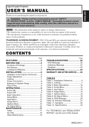
..." section for the pin assignment of these modes will not be connected, and make sure that the projector is compatible with this manual and the separate "SAFETY INSTRUCTIONS". • Before connecting, turn off to all devices to be connected, except for the USB cable. • The cables may need some RGB input modes, the optional Mac adapter is used, the RGB OUT terminal may not function...
..." section for the pin assignment of these modes will not be connected, and make sure that the projector is compatible with this manual and the separate "SAFETY INSTRUCTIONS". • Before connecting, turn off to all devices to be connected, except for the USB cable. • The cables may need some RGB input modes, the optional Mac adapter is used, the RGB OUT terminal may not function...

User Manual
Page 9
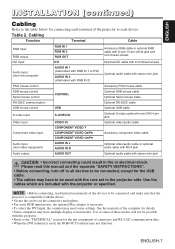
... 1/2B compatible), or by other connecting. NOTE • Plug & play may not operate by connecting an optional DVI cable with notebook computer, set to be used. Power outlet Power Cord AC Inlet Example of system setup DVD Player S-Video Tape Recorder COMPONENT VIDEO CR/PR CB/PB Y AUDIO R IN S-VIDEO IN L VIDEO IN AUDIO 1 2 AUDIO OUT USB IN Display Monitor %7* 1 RGB IN 2 RGB OUT CONTROL Computer (notebook type) Speaker with...
... 1/2B compatible), or by other connecting. NOTE • Plug & play may not operate by connecting an optional DVI cable with notebook computer, set to be used. Power outlet Power Cord AC Inlet Example of system setup DVD Player S-Video Tape Recorder COMPONENT VIDEO CR/PR CB/PB Y AUDIO R IN S-VIDEO IN L VIDEO IN AUDIO 1 2 AUDIO OUT USB IN Display Monitor %7* 1 RGB IN 2 RGB OUT CONTROL Computer (notebook type) Speaker with...
User Manual
Page 10
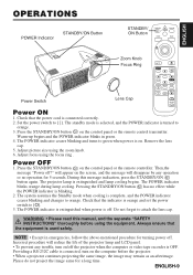
... not project the image same for 5 seconds. Set the power switch to [O]. 3. Always ensure that the power cord is OFF. Providing a RS-232C cable is used safely. Check that the equipment is connected, turn on the computer before using the zoom knob. 6. Warm-up begins and the POWER indicator blinks in emergencies, follow the above-mentioned procedure for turning power off . Check that the indicator is blinking. 2. The POWER indicator blinks orange during lamp cooling. Adjust focus using the focus ring...
... not project the image same for 5 seconds. Set the power switch to [O]. 3. Always ensure that the power cord is OFF. Providing a RS-232C cable is used safely. Check that the equipment is connected, turn on the computer before using the zoom knob. 6. Warm-up begins and the POWER indicator blinks in emergencies, follow the above-mentioned procedure for turning power off . Check that the indicator is blinking. 2. The POWER indicator blinks orange during lamp cooling. Adjust focus using the focus ring...
User Manual
Page 12
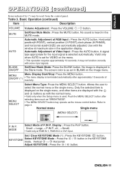
... Blank mode. MENU Menu Display Start/Stop: Press the MENU button. Push the MENU SELECT button after approximately 10 seconds of P.IN P. Normal menu Single menu SETUP INPUT BRIGHT CONTRAST V POSIT H POSIT H PHASE H SIZE COLOR BAL R COLOR BAL B ASPECT IMAGE 100 100 800 OPT. 0 -2 +1 0 0 (MENU SELECT) CONTRAST -2 P.IN P. AUTO Automatic Adjustment at maximum size in the MUTE mode. Use with the window at RGB Input : Press the AUTO button. No image is heard in the application display. The screen color is...
... Blank mode. MENU Menu Display Start/Stop: Press the MENU button. Push the MENU SELECT button after approximately 10 seconds of P.IN P. Normal menu Single menu SETUP INPUT BRIGHT CONTRAST V POSIT H POSIT H PHASE H SIZE COLOR BAL R COLOR BAL B ASPECT IMAGE 100 100 800 OPT. 0 -2 +1 0 0 (MENU SELECT) CONTRAST -2 P.IN P. AUTO Automatic Adjustment at maximum size in the MUTE mode. Use with the window at RGB Input : Press the AUTO button. No image is heard in the application display. The screen color is...

User Manual
Page 14
... on video input mode only, not on the menu. Input Menu SETUP INPUT AUTO RGB VIDEO HDTV IMAGE OPT. Horizontal position (H.POSIT), vertical position (V.POSIT), clock phase (H.PHASE), and horizontal size (H.SIZE) are automatically adjusted. VIDEO (**) Select Video Signal Type: Select the signal type with some input signals. It may correct this problem except for the N-PAL input. • For the COMPONENT VIDEO input, this problem. • This function is set for the input signal with the and buttons...
... on video input mode only, not on the menu. Input Menu SETUP INPUT AUTO RGB VIDEO HDTV IMAGE OPT. Horizontal position (H.POSIT), vertical position (V.POSIT), clock phase (H.PHASE), and horizontal size (H.SIZE) are automatically adjusted. VIDEO (**) Select Video Signal Type: Select the signal type with some input signals. It may correct this problem except for the N-PAL input. • For the COMPONENT VIDEO input, this problem. • This function is set for the input signal with the and buttons...
User Manual
Page 15
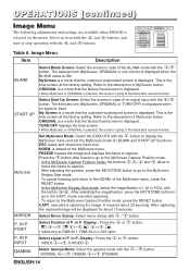
... magnification, press the KEYSTONE button to go to the MyScreen Capture Position mode. P. The selected one colors) is displayed when the BLANK mode is the blue screen at the factory setting. It requires about 10 seconds. VIDEO ↔ S-VIDEO GAMMA Select Gamma Mode: Select the gamma mode with the / button. OPERATIONS (continued) Image Menu The following adjustments and settings are available when IMAGE is displayed. My Screen is a mode that the factory fixed screen is displayed. This is...
... magnification, press the KEYSTONE button to go to the MyScreen Capture Position mode. P. The selected one colors) is displayed when the BLANK mode is the blue screen at the factory setting. It requires about 10 seconds. VIDEO ↔ S-VIDEO GAMMA Select Gamma Mode: Select the gamma mode with the / button. OPERATIONS (continued) Image Menu The following adjustments and settings are available when IMAGE is displayed. My Screen is a mode that the factory fixed screen is displayed. This is...

User Manual
Page 17
... adjustment bar. The audio input can be displayed correctly with the button. This is valid. MIRROR Select Mirror Status: Select the mirror status with the / button. AUTO OFF Set AUTO OFF: Set 1~99 minutes with the / button. SYNC ON G WHISPER SYNC ON G Valid: Select the TURN ON with some input signals when the SYNC ON G is the blue screen at the factory setting. ORIGINAL is a mode that the factory fixed screen is ON. The selected one colors) is displayed...
... adjustment bar. The audio input can be displayed correctly with the button. This is valid. MIRROR Select Mirror Status: Select the mirror status with the / button. AUTO OFF Set AUTO OFF: Set 1~99 minutes with the / button. SYNC ON G WHISPER SYNC ON G Valid: Select the TURN ON with some input signals when the SYNC ON G is the blue screen at the factory setting. ORIGINAL is a mode that the factory fixed screen is ON. The selected one colors) is displayed...
User Manual
Page 18
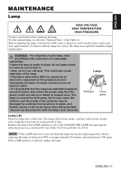
... LAMP indicator is still red, replace the lamp. If the LAMP indicator is also red when the lamp unit reaches high temperature. This could cause injury when being handled. • Do not use old lamp. Before replacing the lamp, switch power OFF, wait approximately 20 minutes, and switch power ON again. ENGLISH-17 Lamp Reflector Front glass Lamp Life Projector lamps have a finite life. Replace the lamp if the LAMP indicator is red, or the CHANGE THE LAMP message appears when the projector is covered...
... LAMP indicator is still red, replace the lamp. If the LAMP indicator is also red when the lamp unit reaches high temperature. This could cause injury when being handled. • Do not use old lamp. Before replacing the lamp, switch power OFF, wait approximately 20 minutes, and switch power ON again. ENGLISH-17 Lamp Reflector Front glass Lamp Life Projector lamps have a finite life. Replace the lamp if the LAMP indicator is red, or the CHANGE THE LAMP message appears when the projector is covered...

User Manual
Page 19
... the control panel, while the lamp timer is not reset correctly. Resetting the Lamp Timer Reset the lamp timer after the LAMP indicator is red, or the CHANGE THE LAMP message is cleared. Press the MENU button on the remote control transmitter, or the RESET button on the bottom of the screwed lamp into the unit. 7. Install the new lamp and tighten the three screws firmly. Loosen the three screws, and gently remove the lamp while holding the grips. Switch the projector OFF, remove the power cord...
... the control panel, while the lamp timer is not reset correctly. Resetting the Lamp Timer Reset the lamp timer after the LAMP indicator is red, or the CHANGE THE LAMP message is cleared. Press the MENU button on the remote control transmitter, or the RESET button on the bottom of the screwed lamp into the unit. 7. Install the new lamp and tighten the three screws firmly. Loosen the three screws, and gently remove the lamp while holding the grips. Switch the projector OFF, remove the power cord...
User Manual
Page 20
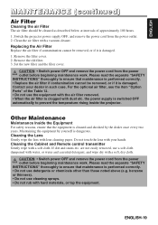
...; Switch power OFF and remove the power cord from the power outlet before beginning maintenance work . Please read the separate "SAFETY INSTRUCTIONS" thoroughly to prevent the temperature rising inside the projector. Do not touch the lens with a soft, dry cloth. CAUTION • Switch power OFF and remove the power cord from the power outlet. 2. the power supply is switched OFF automatically to ensure that maintenance is performed correctly. • Replace the air filter...
...; Switch power OFF and remove the power cord from the power outlet before beginning maintenance work . Please read the separate "SAFETY INSTRUCTIONS" thoroughly to prevent the temperature rising inside the projector. Do not touch the lens with a soft, dry cloth. CAUTION • Switch power OFF and remove the power cord from the power outlet. 2. the power supply is switched OFF automatically to ensure that maintenance is performed correctly. • Replace the air filter...

User Manual
Page 21
.... Always reset the lamp timer after replacing the lamp. Check the specifications of lamp is cut off before * * hr THE POWER WILL TURN OFF by any chance. CHANGE THE LAMP AFTER REPLACING LAMP, RESET THE LAMP TIME. Power will be happened that the lamp is cut off before the function is active. Always reset the lamp timer after replacing the lamp. Table 9. CHANGE THE LAMP It is recommended to reach. However the life of the input signal is switched ON...
.... Always reset the lamp timer after replacing the lamp. Check the specifications of lamp is cut off before * * hr THE POWER WILL TURN OFF by any chance. CHANGE THE LAMP AFTER REPLACING LAMP, RESET THE LAMP TIME. Power will be happened that the lamp is cut off before the function is active. Always reset the lamp timer after replacing the lamp. Table 9. CHANGE THE LAMP It is recommended to reach. However the life of the input signal is switched ON...

User Manual
Page 22
...cover, and switch power ON again. Blinks red - Check fitting of the equipment is extinguished. Blinks Blinks Check whether the ambient temperature is found , or hasn't been fitted in the fan, and switch power ON again. Blinks orange Turns off Turns off ON. The error is below 0°C. Contact your dealer if the same problem occurs again. Please wait. - ENGLISH TROUBLESHOOTING (continued) Indicators Message The POWER indicator, LAMP indicator, and TEMP indicator are blocked, whether the air filter is not operating. Lights green Turns...
...cover, and switch power ON again. Blinks red - Check fitting of the equipment is extinguished. Blinks Blinks Check whether the ambient temperature is found , or hasn't been fitted in the fan, and switch power ON again. Blinks orange Turns off Turns off ON. The error is below 0°C. Contact your dealer if the same problem occurs again. Please wait. - ENGLISH TROUBLESHOOTING (continued) Indicators Message The POWER indicator, LAMP indicator, and TEMP indicator are blocked, whether the air filter is not operating. Lights green Turns...

User Manual
Page 23
... signal input. Replace with the following chart. Plug the power cord into an AC 8,9 disconnected. Connect correctly. 7,8 The projector is set . The volume is present but no video. TROUBLESHOOTING (continued) Symptom Before requesting repair, check in accordance with a new lamp. 17 WHISPER mode is not correctly connected. Connect correctly. 7,8 Audio is set . 10 No video or audio. Remove the lens cap. 9 Colors are not correctly Adjust the video. 12 poor. Adjust the video. 12 Images are not correctly adjusted. button and...
... signal input. Replace with the following chart. Plug the power cord into an AC 8,9 disconnected. Connect correctly. 7,8 The projector is set . The volume is present but no video. TROUBLESHOOTING (continued) Symptom Before requesting repair, check in accordance with a new lamp. 17 WHISPER mode is not correctly connected. Connect correctly. 7,8 Audio is set . 10 No video or audio. Remove the lens cap. 9 Colors are not correctly Adjust the video. 12 poor. Adjust the video. 12 Images are not correctly adjusted. button and...

User Manual
Page 32
... computer. Some times, the projector ignores RS-232C commands during warm-up. TECHNICAL (continued) Requesting projector status (Get command) (1) Send the request code Header + Command data ('02H'+'00H'+ type (2 bytes) +'00H'+'00H') from the computer to the projector. (2) The projector changes the setting based on the above setting code. (3) The projector returns the response code '06H' to the computer. Using the projector default settings (Reset Command) (1) The computer sends the default setting code Header + Command data ('06H'+'00H...
... computer. Some times, the projector ignores RS-232C commands during warm-up. TECHNICAL (continued) Requesting projector status (Get command) (1) Send the request code Header + Command data ('02H'+'00H'+ type (2 bytes) +'00H'+'00H') from the computer to the projector. (2) The projector changes the setting based on the above setting code. (3) The projector returns the response code '06H' to the computer. Using the projector default settings (Reset Command) (1) The computer sends the default setting code Header + Command data ('06H'+'00H...
User Manual
Page 34
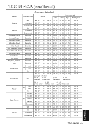
... (continued) Command data chart Names Operation type Header Command data CRC Action Type Setting code Get BE ...Size Reset Execute BE EF 03 06 00 68 D2 06 00 04 70 00 00 Color Balance R Reset Execute BE EF 03 06 00 94 D3 06 00 05 70 00 00 Color Balance B Reset...00 00 Error Status (Example of Return) 00 00 01 00 02 00 03 00 Get (Normal) (Cover-error) (Fan-error) (Lamp-error) Power OFF Set ON Get RGB1 04 00 05 00 06 00 (Temp-error) (Air flow-error) (Lamp-Time-over)... BE EF 03 06 00 3E D0 01 00 00 20 04 00 Input Source Set Video SVideo BE EF BE EF 03 06 00 6E D3 01 00 00...
... (continued) Command data chart Names Operation type Header Command data CRC Action Type Setting code Get BE ...Size Reset Execute BE EF 03 06 00 68 D2 06 00 04 70 00 00 Color Balance R Reset Execute BE EF 03 06 00 94 D3 06 00 05 70 00 00 Color Balance B Reset...00 00 Error Status (Example of Return) 00 00 01 00 02 00 03 00 Get (Normal) (Cover-error) (Fan-error) (Lamp-error) Power OFF Set ON Get RGB1 04 00 05 00 06 00 (Temp-error) (Air flow-error) (Lamp-Time-over)... BE EF 03 06 00 3E D0 01 00 00 20 04 00 Input Source Set Video SVideo BE EF BE EF 03 06 00 6E D3 01 00 00...

Brochure
Page 1
Remote control with laser pointer Model name Liquid crystal panel structure Number of pixels Resolution Video RGB Colors Aspect ratio Lens Throw ratio (distance:width) Lamp Expected lamp life Brightness Contrast ratio Speakers Power supply Power consumption Operating temperature Input signals RGB Composite video Component video Acoustic noise level H sync V sync Vertical keystone correction Horizontal keystone correction Approvals RGB input Digital RGB Analog RGB Audio Audio output Video input S-video Composite video Component video Audio Control terminals ...
Remote control with laser pointer Model name Liquid crystal panel structure Number of pixels Resolution Video RGB Colors Aspect ratio Lens Throw ratio (distance:width) Lamp Expected lamp life Brightness Contrast ratio Speakers Power supply Power consumption Operating temperature Input signals RGB Composite video Component video Acoustic noise level H sync V sync Vertical keystone correction Horizontal keystone correction Approvals RGB input Digital RGB Analog RGB Audio Audio output Video input S-video Composite video Component video Audio Control terminals ...


