
Instruction Manual
Page 7
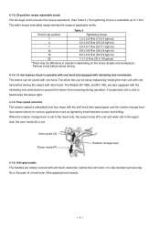
... while turning the sleeve with the shift knob (two-speed gear) and the rotation change lever 4-1-6. Save mode (S) Power mode (P) Rotation change lever (two-speed switch) for various applications such as tightening small-diameter screws and...
... while turning the sleeve with the shift knob (two-speed gear) and the rotation change lever 4-1-6. Save mode (S) Power mode (P) Rotation change lever (two-speed switch) for various applications such as tightening small-diameter screws and...
Instruction Manual
Page 9
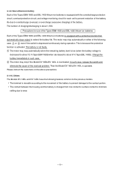
... of the overload problem. Others The Models DV 18DL and DV 14DL have the following case 1 or 2 even if the switch is depressed continuously during operation. Charge the battery immediately in either of charging/discharging is movable according to the previous models. Please...with the overdischarge protection circuit, overload protection circuit, and voltage monitoring circuit for use of the Types EBM 1830 and EBL 1430 lithium-ion batteries Each of the battery. Precautions for each cell to prevent reduction of the battery life due to overdischarge (overuse) or overcharge...
... of the overload problem. Others The Models DV 18DL and DV 14DL have the following case 1 or 2 even if the switch is depressed continuously during operation. Charge the battery immediately in either of charging/discharging is movable according to the previous models. Please...with the overdischarge protection circuit, overload protection circuit, and voltage monitoring circuit for use of the Types EBM 1830 and EBL 1430 lithium-ion batteries Each of the battery. Precautions for each cell to prevent reduction of the battery life due to overdischarge (overuse) or overcharge...
Instruction Manual
Page 10
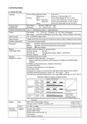
... Torque Type of the pilot lamp Before Blinks charging (Red) 0.5 sec. ABS resin (black) Sealed cylindrical lithium-ion storage battery Nominal voltage .......... OFF Charging Flickers impossible (Red) 0.1 sec. ON 0.1 sec. OFF Malfunction in...Screw driving Machine screw ......... 6 mm (1/4") Wood screw 8 mm dia. DC 18V Nominal life Charging/discharging: Approx. 1,500 times Nominal capacity ......... 3.0 Ah ... switch with push button for cooling the battery, the Model UC 18YRL cools the overheated battery by the cooling fan. x 100 mm (#20 x 4") Drilling Brick...
... Torque Type of the pilot lamp Before Blinks charging (Red) 0.5 sec. ABS resin (black) Sealed cylindrical lithium-ion storage battery Nominal voltage .......... OFF Charging Flickers impossible (Red) 0.1 sec. ON 0.1 sec. OFF Malfunction in...Screw driving Machine screw ......... 6 mm (1/4") Wood screw 8 mm dia. DC 18V Nominal life Charging/discharging: Approx. 1,500 times Nominal capacity ......... 3.0 Ah ... switch with push button for cooling the battery, the Model UC 18YRL cools the overheated battery by the cooling fan. x 100 mm (#20 x 4") Drilling Brick...
Instruction Manual
Page 11
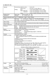
...EBL 1430 2 Phillips (plus) driver bit (No. 2 1 Side handle ...1 Case (injection-molded 1 --- 8 --- x 75 mm (#20 x 3") Drilling Brick 14 mm (9/16") [Depth 30 mm (1-1/4")] Metal •••Mild steel ...... 13 mm (1/2") [Thickness 1.6 mm (1/16")] Aluminum ..... 13...switch with push button for cooling the battery, the Model UC 18YRL cools the overheated battery by the cooling fan. V system) Battery temperature detection (dT/dt system) for Ni-MH and SUPER Ni-MH batteries (2) Battery surface temperature detection (thermistor) (3) 120-minute timer (4) Stop current detection (Li-ion...
...EBL 1430 2 Phillips (plus) driver bit (No. 2 1 Side handle ...1 Case (injection-molded 1 --- 8 --- x 75 mm (#20 x 3") Drilling Brick 14 mm (9/16") [Depth 30 mm (1-1/4")] Metal •••Mild steel ...... 13 mm (1/2") [Thickness 1.6 mm (1/16")] Aluminum ..... 13...switch with push button for cooling the battery, the Model UC 18YRL cools the overheated battery by the cooling fan. V system) Battery temperature detection (dT/dt system) for Ni-MH and SUPER Ni-MH batteries (2) Battery surface temperature detection (thermistor) (3) 120-minute timer (4) Stop current detection (Li-ion...
Instruction Manual
Page 12
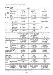
Model DV 18DL Maker HITACHI Model DV 18DL DV 18DMR Machine screw Screw driving Wood screw 6 mm (1/4") 8 mm dia. capacity Brick 16 mm (5/8") 16 mm (5/8") Mild steel Drilling Aluminum 13 mm (1/2") 13 mm (1/2") 13 mm (1/2") 13 mm (1/2") Soft wood 50 mm (2")...8226;cm) (713 in -lbs.) Type Single sleeve Single sleeve Drill Capacity 13 mm (1/2") 13 mm (1/2") chuck Outer material Metal Metal Locking device Equipped Equipped Type Variable speed Variable speed Switch Feedback circuit Equipped Equipped Electric brake Equipped Equipped Automatic spindle lock ...
Model DV 18DL Maker HITACHI Model DV 18DL DV 18DMR Machine screw Screw driving Wood screw 6 mm (1/4") 8 mm dia. capacity Brick 16 mm (5/8") 16 mm (5/8") Mild steel Drilling Aluminum 13 mm (1/2") 13 mm (1/2") 13 mm (1/2") 13 mm (1/2") Soft wood 50 mm (2")...8226;cm) (713 in -lbs.) Type Single sleeve Single sleeve Drill Capacity 13 mm (1/2") 13 mm (1/2") chuck Outer material Metal Metal Locking device Equipped Equipped Type Variable speed Variable speed Switch Feedback circuit Equipped Equipped Electric brake Equipped Equipped Automatic spindle lock ...
Instruction Manual
Page 13
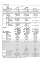
...Power mode 0 --- 200/min. 0 --- 400/min. 0 --- 850/min. 0 --- 1,750/min. Low: 0 --- 6,000/min. Model DV 14DL Maker HITACHI Model DV 14DL DV 14DMR Machine screw Screw driving Wood screw 6 mm (1/4") 8 mm dia. torque 52 N•m (530 kgf•cm) (460 in-lbs.) ...52 N•m (530 kgf•cm) (460 in -lbs.) Type Capacity Drill chuck Outer material Locking device Type Switch Feedback circuit Electric brake Automatic spindle lock Reversing switch Replaceable carbon brushes Replaceable armature Handle shape Soft-grip handle Side handle Belt hook Strap Battery ...
...Power mode 0 --- 200/min. 0 --- 400/min. 0 --- 850/min. 0 --- 1,750/min. Low: 0 --- 6,000/min. Model DV 14DL Maker HITACHI Model DV 14DL DV 14DMR Machine screw Screw driving Wood screw 6 mm (1/4") 8 mm dia. torque 52 N•m (530 kgf•cm) (460 in-lbs.) ...52 N•m (530 kgf•cm) (460 in -lbs.) Type Capacity Drill chuck Outer material Locking device Type Switch Feedback circuit Electric brake Automatic spindle lock Reversing switch Replaceable carbon brushes Replaceable armature Handle shape Soft-grip handle Side handle Belt hook Strap Battery ...
Instruction Manual
Page 18
... will not improve working efficiency. (3) Do not insert a foreign object into the vent hole. (4) Use at low speed. Locking of the motor in cordless driver drills is done with the Models DV 18DL and DV 14DL is available, the absence of the battery. Accordingly, they are battery driven, the output of... Salespersons must be done at the thrust of 100 to 150 N (10 to 15 kgf, 22 to reverse rotation, or by setting the switch to 33 lbs.) The drilling speed of times the batteries have a bearing on the ambient temperature during use and charging, and the number of this tool has vent...
... will not improve working efficiency. (3) Do not insert a foreign object into the vent hole. (4) Use at low speed. Locking of the motor in cordless driver drills is done with the Models DV 18DL and DV 14DL is available, the absence of the battery. Accordingly, they are battery driven, the output of... Salespersons must be done at the thrust of 100 to 150 N (10 to 15 kgf, 22 to reverse rotation, or by setting the switch to 33 lbs.) The drilling speed of times the batteries have a bearing on the ambient temperature during use and charging, and the number of this tool has vent...
Instruction Manual
Page 19
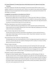
... chuck. The relationship between the amount the trigger switch is depressed (in millimeters) and the rotation speed is increased. Repeated locking of the drill causes excessive current flow from the batteries which the trigger switch is depresed. Please instruct the customers to avoid...continuous operation under certain conditions, operating conditions are intended for drilling capacities of the trigger switch (mm) Fig. 2 --- 16 --- In particular, when drilling through the material to differences in the discharge condition of the drill bit in use . For this capability is not as ...
... chuck. The relationship between the amount the trigger switch is depressed (in millimeters) and the rotation speed is increased. Repeated locking of the drill causes excessive current flow from the batteries which the trigger switch is depresed. Please instruct the customers to avoid...continuous operation under certain conditions, operating conditions are intended for drilling capacities of the trigger switch (mm) Fig. 2 --- 16 --- In particular, when drilling through the material to differences in the discharge condition of the drill bit in use . For this capability is not as ...
Instruction Manual
Page 20
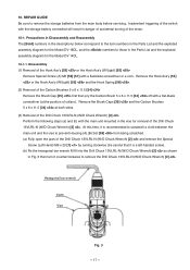
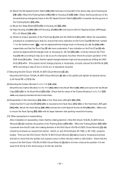
... with the main unit mounted in the Parts List and the exploded assembly diagram for the Model DV 18DL, and the numbers to remove the Drill Chuck 13VLRL-N (W/O Chuck Wrench) [2] . 10. Inadvertent triggering of the motor. 10-1. Precautions in Disassembly and Reassembly The [Bold] numbers ... is a left-handed screw). (b) Fix the hexagonal bar wrench M10 into the Drill Chuck 13VLRL-N (W/O Chuck Wrench) [2] as shown in Fig. 3 then turn it counterclockwise to those in danger of accidental turning of the switch with a flat-blade screwdriver or a coin. Disassembly (1) Removal of the Hook Ass...
... with the main unit mounted in the Parts List and the exploded assembly diagram for the Model DV 18DL, and the numbers to remove the Drill Chuck 13VLRL-N (W/O Chuck Wrench) [2] . 10. Inadvertent triggering of the motor. 10-1. Precautions in Disassembly and Reassembly The [Bold] numbers ... is a left-handed screw). (b) Fix the hexagonal bar wrench M10 into the Drill Chuck 13VLRL-N (W/O Chuck Wrench) [2] as shown in Fig. 3 then turn it counterclockwise to those in danger of accidental turning of the switch with a flat-blade screwdriver or a coin. Disassembly (1) Removal of the Hook Ass...
Instruction Manual
Page 21
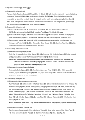
Thus the armature unit is strong. Parts are apt to roll. (b) Removal of the Switch Plate [5] Turn the switch flange so as to fit the projection of the Switch Plate [5] , then remove the Switch Plate [5] from the rear of Housing (B) [38] , gently remove Housing (B) [38] . .... (8) Disassembly of the gear unit (a) Disassembly of the deceleration mechanism Turn Washer (B) [29] mounted in the Rear Case [20] counterclockwise to the recess of the switch flange to remove. Take out the First Ring Gear [28] , Planet Gear (A) Set (4 pcs.) [27] , Pinion (B) [26] , Planet Gear (B) Set ...
Thus the armature unit is strong. Parts are apt to roll. (b) Removal of the Switch Plate [5] Turn the switch flange so as to fit the projection of the Switch Plate [5] , then remove the Switch Plate [5] from the rear of Housing (B) [38] , gently remove Housing (B) [38] . .... (8) Disassembly of the gear unit (a) Disassembly of the deceleration mechanism Turn Washer (B) [29] mounted in the Rear Case [20] counterclockwise to the recess of the switch flange to remove. Take out the First Ring Gear [28] , Planet Gear (A) Set (4 pcs.) [27] , Pinion (B) [26] , Planet Gear (B) Set ...
Instruction Manual
Page 22
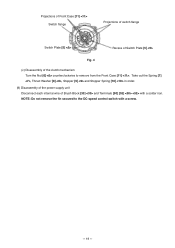
Take out the Spring [7] , Thrust Washer [8] , Stopper [9] and Stopper Spring [10] in order. (9) Disassembly of the power supply unit Disconnect each internal wire of the clutch mechanism Turn the Nut [6] counterclockwise to the DC-speed control switch with a solder iron. NOTE: Do not remove the fin secured to remove from the Front Case [11] . Projections of Front Case [11] Switch flange Projections of switch flange Switch Plate [5] Recess of Switch Plate [5] Fig. 4 (c) Disassembly of Brush Block [33] and Terminals [50] [52] with a screw. --- 19 ---
Take out the Spring [7] , Thrust Washer [8] , Stopper [9] and Stopper Spring [10] in order. (9) Disassembly of the power supply unit Disconnect each internal wire of the clutch mechanism Turn the Nut [6] counterclockwise to the DC-speed control switch with a solder iron. NOTE: Do not remove the fin secured to remove from the Front Case [11] . Projections of Front Case [11] Switch flange Projections of switch flange Switch Plate [5] Recess of Switch Plate [5] Fig. 4 (c) Disassembly of Brush Block [33] and Terminals [50] [52] with a screw. --- 19 ---
Instruction Manual
Page 28
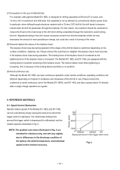
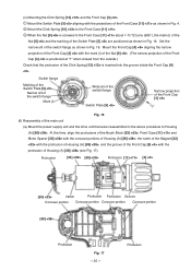
...is positioned at "1" when viewed from the outside.) Check that were reassembled in Fig. 16. Protrusion Set the narrow slit of the switch flange as shown in Fig. 16. Protrusion [32] [30] Protrusion [11] [4] [33] Notch Protrusion Protrusion Groove Concave portion ...Concave portion Concave portion Concave portion [38] Protrusion Fig. 17 --- 25 --- Switch flange Marking of the Switch Plate [5] Narrow slit of the switch flange Mark (i) Wide slit of the switch flange Switch Plate [5] Narrow projection of the Front Cap [4] "1" Fig. 16 (6) Reassembly of the...
...is positioned at "1" when viewed from the outside.) Check that were reassembled in Fig. 16. Protrusion Set the narrow slit of the switch flange as shown in Fig. 16. Protrusion [32] [30] Protrusion [11] [4] [33] Notch Protrusion Protrusion Groove Concave portion ...Concave portion Concave portion Concave portion [38] Protrusion Fig. 17 --- 25 --- Switch flange Marking of the Switch Plate [5] Narrow slit of the switch flange Mark (i) Wide slit of the switch flange Switch Plate [5] Narrow projection of the Front Cap [4] "1" Fig. 16 (6) Reassembly of the...
Instruction Manual
Page 29
... of reassembly, check that the V-Lock Nut M5 [54] is mounted to the hammer mark " " can be clockwise as it is improperly mounted. (7) Mounting the Drill Chuck 13VLRL-N (W/O Chuck Wrench) [2] Mount the Drill Chuck 13VLRL-N (W/O Chuck Wrench) [2] to the spindle and tighten the Special Screw ...[34] to the Brush Block [33] and secure the two Brush Caps [35] to Housing (A) [38] . Check that the Front Cap [4] turns moderately. Switch on Housing (A). (B) Set [38] respectively and that the claws of the Carbon Brushes 5 x 6 x 11.5 [34] are properly inserted into the groove of ...
... of reassembly, check that the V-Lock Nut M5 [54] is mounted to the hammer mark " " can be clockwise as it is improperly mounted. (7) Mounting the Drill Chuck 13VLRL-N (W/O Chuck Wrench) [2] Mount the Drill Chuck 13VLRL-N (W/O Chuck Wrench) [2] to the spindle and tighten the Special Screw ...[34] to the Brush Block [33] and secure the two Brush Caps [35] to Housing (A) [38] . Check that the Front Cap [4] turns moderately. Switch on Housing (A). (B) Set [38] respectively and that the claws of the Carbon Brushes 5 x 6 x 11.5 [34] are properly inserted into the groove of ...

Instruction Manual
Page 31
11. STANDARD REPAIR TIME (UNIT) SCHEDULES Variable MODEL Fixed 10 20 30 40 50 60 DV 18DL Work Flow DV 14DL General Assembly Housing (A).(B) Set Armature and Pinion Set Magnet Brush Block DC-Speed Control Switch Shift Knob Gear Box Ass'y Front Cap Drill Chuck (Keyless) Nut Spring Front Case Lock Ring Hook Ass'y Ring Gear Carrier Planet Gear (C) Set Rear Case Shift Arm Slide Ring Gear Pinion (C) Planet Gear (B) Set Pinion (B) Planet Gear (A) Set First Ring Gear --- 28 ---
11. STANDARD REPAIR TIME (UNIT) SCHEDULES Variable MODEL Fixed 10 20 30 40 50 60 DV 18DL Work Flow DV 14DL General Assembly Housing (A).(B) Set Armature and Pinion Set Magnet Brush Block DC-Speed Control Switch Shift Knob Gear Box Ass'y Front Cap Drill Chuck (Keyless) Nut Spring Front Case Lock Ring Hook Ass'y Ring Gear Carrier Planet Gear (C) Set Rear Case Shift Arm Slide Ring Gear Pinion (C) Planet Gear (B) Set Pinion (B) Planet Gear (A) Set First Ring Gear --- 28 ---
Instruction Manual
Page 33
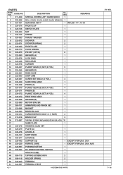
PARTS ITEM NO. USED 1 REMARKS 2 323-898 DRILL CHUCK 13VLRL-N (W/O CHUCK WRENCH) 1 3 324-061 GEAR BOX ASS'Y 1 INCLUD. 4-11, 13-30 4 324-074 FRONT CAP 1 5 324-136 SWITCH PLATE 1 6 324-064 NUT 1 7 324-135 SPRING 1 8 324-063 THRUST WASHER 1 9 322-972 STOPPER 2 10 322-971 STOPPER SPRING 2...EXCEPT FOR USA, CAN * 44 323-229 FERRITE CORE 1 EXCEPT FOR USA, CAN, AUS 45 322-997 PUSHING BUTTON 1 46 322-994 DC-SPEED CONTROL SWITCH 1 47 HITACHI LABEL 1 48 958-715 TAPPING SCREW D4X10 2 49 996-118 HOLDER SPRING 2 50 323-003 TERMINAL 1 51 320-997 TERMINAL PIECE 1 --- 2 ---...
PARTS ITEM NO. USED 1 REMARKS 2 323-898 DRILL CHUCK 13VLRL-N (W/O CHUCK WRENCH) 1 3 324-061 GEAR BOX ASS'Y 1 INCLUD. 4-11, 13-30 4 324-074 FRONT CAP 1 5 324-136 SWITCH PLATE 1 6 324-064 NUT 1 7 324-135 SPRING 1 8 324-063 THRUST WASHER 1 9 322-972 STOPPER 2 10 322-971 STOPPER SPRING 2...EXCEPT FOR USA, CAN * 44 323-229 FERRITE CORE 1 EXCEPT FOR USA, CAN, AUS 45 322-997 PUSHING BUTTON 1 46 322-994 DC-SPEED CONTROL SWITCH 1 47 HITACHI LABEL 1 48 958-715 TAPPING SCREW D4X10 2 49 996-118 HOLDER SPRING 2 50 323-003 TERMINAL 1 51 320-997 TERMINAL PIECE 1 --- 2 ---...
Instruction Manual
Page 37
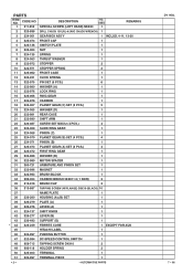
USED 1 REMARKS DRILL CHUCK 13VLRL-N (W/O CHUCK WRENCH) 1 GEAR BOX ASS'Y 1 INCLUD. 4-11, 13-30 FRONT CAP 1 SWITCH PLATE 1 NUT 1 SPRING 1 THRUST WASHER 1 STOPPER 2 10 322-971 STOPPER SPRING 2 11 324-062 FRONT CASE 1 12 323-231 CLICK ...) D3X16 (BLACK) 10 NAME PLATE 1 HOUSING (A).(B) SET 1 PLATE (A) 1 LEVER (A) 1 SHIFT KNOB 1 LEVER (B) 1 SUPPORT (D) 1 FERRITE CORE 1 HITACHI LABEL 1 PUSHING BUTTON 1 EXCEPT FOR AUS 47 322-994 DC-SPEED CONTROL SWITCH 1 48 958-715 TAPPING SCREW D4X10 2 49 996-118 HOLDER SPRING 2 50 323-003 TERMINAL 1 51 320-997 TERMINAL...
USED 1 REMARKS DRILL CHUCK 13VLRL-N (W/O CHUCK WRENCH) 1 GEAR BOX ASS'Y 1 INCLUD. 4-11, 13-30 FRONT CAP 1 SWITCH PLATE 1 NUT 1 SPRING 1 THRUST WASHER 1 STOPPER 2 10 322-971 STOPPER SPRING 2 11 324-062 FRONT CASE 1 12 323-231 CLICK ...) D3X16 (BLACK) 10 NAME PLATE 1 HOUSING (A).(B) SET 1 PLATE (A) 1 LEVER (A) 1 SHIFT KNOB 1 LEVER (B) 1 SUPPORT (D) 1 FERRITE CORE 1 HITACHI LABEL 1 PUSHING BUTTON 1 EXCEPT FOR AUS 47 322-994 DC-SPEED CONTROL SWITCH 1 48 958-715 TAPPING SCREW D4X10 2 49 996-118 HOLDER SPRING 2 50 323-003 TERMINAL 1 51 320-997 TERMINAL...


