
Operation Manual
Page 1
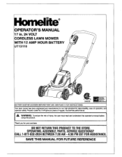
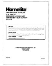
Homehmttil e® OPERATOR'S MANUAL 17 in. 24 VOLT -d:,, CORDLESS LAWN MOWER i WITH 12 AMP HOUR BATTERY \ UT13110 , ,, ......,, , ,i 4 e":15 Ow**V.-.,i,-t,i,q•li„i q iia,-t34r‹l;:-.ig:lfi I C9 . 244026 =quso tedeamm wow chirp, kra §0A1Pflfneltt BATTERY MUST BE CHARGED BEFORE FIRST USE. OPERATING, ASSEMBLY, PARTS, SERVICE QUESTIONS? Your lawn mower has been engineered and manufactured to our high standard for your purchase. CALL 1-877-932-2634 BETWEEN...
Homehmttil e® OPERATOR'S MANUAL 17 in. 24 VOLT -d:,, CORDLESS LAWN MOWER i WITH 12 AMP HOUR BATTERY \ UT13110 , ,, ......,, , ,i 4 e":15 Ow**V.-.,i,-t,i,q•li„i q iia,-t34r‹l;:-.ig:lfi I C9 . 244026 =quso tedeamm wow chirp, kra §0A1Pflfneltt BATTERY MUST BE CHARGED BEFORE FIRST USE. OPERATING, ASSEMBLY, PARTS, SERVICE QUESTIONS? Your lawn mower has been engineered and manufactured to our high standard for your purchase. CALL 1-877-932-2634 BETWEEN...
Operation Manual
Page 2
...handling. GENERAL SAFETY RULES WARNING: The batteries in insecticides, herbicides and pesticides * arsenic and chromium from exposure to these chemicals are specially designed to filter out microscopic particles. WARNING: Some dust and debris created by the use... harm. Wash hands after handling. - ■ Introduction ■ General Safety Rules ■ Specific Safety Rules ■ Symbols ■ Features ■ Assembly r Operation ■ Maintenance ■ Troubleshooting ■ Exploded View/Parts List • Warranty • Parts Ordering / Service TABLE OF CONTENTS I 2...
...handling. GENERAL SAFETY RULES WARNING: The batteries in insecticides, herbicides and pesticides * arsenic and chromium from exposure to these chemicals are specially designed to filter out microscopic particles. WARNING: Some dust and debris created by the use... harm. Wash hands after handling. - ■ Introduction ■ General Safety Rules ■ Specific Safety Rules ■ Symbols ■ Features ■ Assembly r Operation ■ Maintenance ■ Troubleshooting ■ Exploded View/Parts List • Warranty • Parts Ordering / Service TABLE OF CONTENTS I 2...

Operation Manual
Page 3
... blade.Stay behind to each use , mower should always be thrown by the manufacturer. • Clear the work area before cleaning the lawn mower,or unclogging the discharge opening at the rate for which may result in serious personal injury. • Keep machine in loss of all instructions listed below and on slopes. SPECIFIC SAFETY RULES • Do not operate the mower...
... blade.Stay behind to each use , mower should always be thrown by the manufacturer. • Clear the work area before cleaning the lawn mower,or unclogging the discharge opening at the rate for which may result in serious personal injury. • Keep machine in loss of all instructions listed below and on slopes. SPECIFIC SAFETY RULES • Do not operate the mower...
Operation Manual
Page 4
SPECIFIC SAFETY RULES ■ If the lawn mower strikes a foreign object, follow these steps: • Release the switch control lever and stop the lawn mower. • Remove the switch key • Thoroughly inspect the mower for any damage. • Repair any damage before restarting and continuing to operate the mower. ■ Stop the motor, remove the switch key, and wait until you loan someone this product. Service or maintenance performed by the battery charger...
SPECIFIC SAFETY RULES ■ If the lawn mower strikes a foreign object, follow these steps: • Release the switch control lever and stop the lawn mower. • Remove the switch key • Thoroughly inspect the mower for any damage. • Repair any damage before restarting and continuing to operate the mower. ■ Stop the motor, remove the switch key, and wait until you loan someone this product. Service or maintenance performed by the battery charger...

Operation Manual
Page 5
... damp locations. Electric Shock Failure to use in electric shock. Page 5 SYMBOL NAME DESIGNATION/EXPLANATION V Volts Voltage A Amperes Current Hz Hertz Frequency (cycles per second) W Watt Power hrs Hours _ gal Gallon Time - Alwayswear safety goggles orsafety glasseswith side shieldsand, as necessary, a full face shield when operating this product. Please study them and learn their meaning. Read The Operators Manual...
... damp locations. Electric Shock Failure to use in electric shock. Page 5 SYMBOL NAME DESIGNATION/EXPLANATION V Volts Voltage A Amperes Current Hz Hertz Frequency (cycles per second) W Watt Power hrs Hours _ gal Gallon Time - Alwayswear safety goggles orsafety glasseswith side shieldsand, as necessary, a full face shield when operating this product. Please study them and learn their meaning. Read The Operators Manual...
Operation Manual
Page 6
... Call Homelite customer service for use eye protection which , if not avoided, could result in death or serious injury. Always use over eyeglasses or standard safety glasses with ANSI Z87.1. SAVE THESE INSTRUCTIONS Page ...operator's manual. Before beginning power tool operation, always wear safety goggles or safety glasses with this product until you do not understand the warnings and instructions in the operator's manual, do not attempt to use only identical replacement parts. SYMBOLS The following signal words and meanings are intended to explain the levels of any power...
... Call Homelite customer service for use eye protection which , if not avoided, could result in death or serious injury. Always use over eyeglasses or standard safety glasses with ANSI Z87.1. SAVE THESE INSTRUCTIONS Page ...operator's manual. Before beginning power tool operation, always wear safety goggles or safety glasses with this product until you do not understand the warnings and instructions in the operator's manual, do not attempt to use only identical replacement parts. SYMBOLS The following signal words and meanings are intended to explain the levels of any power...
Operation Manual
Page 7
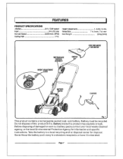
...) SIDE DISCHARGE DEFLECTOR BATTERY METER CHARGER Fig. 1 This product contains a rechargeable sealed lead- Pagel Do not dispose of damaged or worn out battery packs,contact your local waste disposal agency, or the local Environmental Protection Agency for disposal. acid battery. Take the battery to 4 in. 7 in a standard receptacle or have it incinerated. Height Adjustments Wheel Size Net Weight MOTOR/BLADE CONTROL ASSEMBLY HEIGHT ADJUSTMENT LEVER cm SWITCH KEY I 1-3/4in. Battery must...
...) SIDE DISCHARGE DEFLECTOR BATTERY METER CHARGER Fig. 1 This product contains a rechargeable sealed lead- Pagel Do not dispose of damaged or worn out battery packs,contact your local waste disposal agency, or the local Environmental Protection Agency for disposal. acid battery. Take the battery to 4 in. 7 in a standard receptacle or have it incinerated. Height Adjustments Wheel Size Net Weight MOTOR/BLADE CONTROL ASSEMBLY HEIGHT ADJUSTMENT LEVER cm SWITCH KEY I 1-3/4in. Battery must...
Operation Manual
Page 8
... 1. HEIGHT ADJUSTMENT LEVER The height adjustment lever provides cutting height adjustments. MOTOR/BLADE CONTROL ASSEMBLY The motor/blade control, located on the upper handle of this product, familiarize yourself with all items listed in this product until the parts are damaged or missing do not make sure no breakage or damage occurred during shipping. ▪ Do not discard the packing material until assembly is preferred. The grass clippings produced when using the side discharge deflector...
... 1. HEIGHT ADJUSTMENT LEVER The height adjustment lever provides cutting height adjustments. MOTOR/BLADE CONTROL ASSEMBLY The motor/blade control, located on the upper handle of this product, familiarize yourself with all items listed in this product until the parts are damaged or missing do not make sure no breakage or damage occurred during shipping. ▪ Do not discard the packing material until assembly is preferred. The grass clippings produced when using the side discharge deflector...

Operation Manual
Page 9
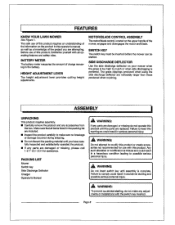
... the handle. • Pull up and back on the upper handle to raise the handle into place securely. • Tighten the handle.knobs on both sides of the door. • Lower the deflector until the hooks on the deflector with damaged safety devices. Failure to secure. ASSEMBLY A WARNING: Never operate the mower without the proper safety devices in serious personal injury. INSTALLING SIDE DISCHARGE DEFLECTOR See...
... the handle. • Pull up and back on the upper handle to raise the handle into place securely. • Tighten the handle.knobs on both sides of the door. • Lower the deflector until the hooks on the deflector with damaged safety devices. Failure to secure. ASSEMBLY A WARNING: Never operate the mower without the proper safety devices in serious personal injury. INSTALLING SIDE DISCHARGE DEFLECTOR See...
Operation Manual
Page 10
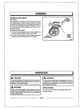
... back of the mower, ■ To lower the blade height, grasp the height adjustment lever and move it toward the front of this product for the purpose listed below: Mowing your lawn. APPLICATIONS You may use of attachments or accessories not recommended can result in ?-74Alf HIGHEST BLADE SETTING HEIGHT DJUSTMENT LEVER LOWEST BLADE SETTING Fig. 4 OPERATION A WARNING: Do not allow familiarity with side shields when operating this type of a second...
... back of the mower, ■ To lower the blade height, grasp the height adjustment lever and move it toward the front of this product for the purpose listed below: Mowing your lawn. APPLICATIONS You may use of attachments or accessories not recommended can result in ?-74Alf HIGHEST BLADE SETTING HEIGHT DJUSTMENT LEVER LOWEST BLADE SETTING Fig. 4 OPERATION A WARNING: Do not allow familiarity with side shields when operating this type of a second...
Operation Manual
Page 11
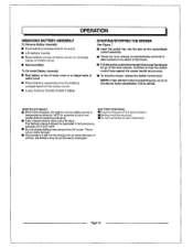
... temperatures down to bo fully discharged before Initial use . II Make sure the power supply is less than 24 hours. The lawn mower comes with a maintenance free, sealed 24 volt storage battery. ▪ Remove the switch key. • Charge the battery pack only with the charger provided. These lights will soon require charging. OPERATION BATTERY METER See Figure 5. If the AMBER light illuminates, the battery will only illuminate when...
... temperatures down to bo fully discharged before Initial use . II Make sure the power supply is less than 24 hours. The lawn mower comes with a maintenance free, sealed 24 volt storage battery. ▪ Remove the switch key. • Charge the battery pack only with the charger provided. These lights will soon require charging. OPERATION BATTERY METER See Figure 5. If the AMBER light illuminates, the battery will only illuminate when...
Operation Manual
Page 12
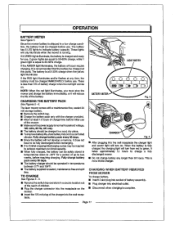
... mower, release the switch control lever. Page 12 NOTE:A high-pitched noise and sparking may be permanently damaged. Continue to two weeks before requiring charging. ■ Fully charge battery pack every 30 days. STARTING/STOPPING THE MOWER See Figure 7. ■ Insert the switch key Into the slot on the motor/blade control assembly. ■ Rotate the lever release counterclockwise and hold the switch control lever against the mower handle as the electric motor decelerates. The battery...
... mower, release the switch control lever. Page 12 NOTE:A high-pitched noise and sparking may be permanently damaged. Continue to two weeks before requiring charging. ■ Fully charge battery pack every 30 days. STARTING/STOPPING THE MOWER See Figure 7. ■ Insert the switch key Into the slot on the motor/blade control assembly. ■ Rotate the lever release counterclockwise and hold the switch control lever against the mower handle as the electric motor decelerates. The battery...

Operation Manual
Page 13
... not attempt to slip and fall can hide obstacles. SWITCH KEY SWITCH KEY SWITCH JI CONTROL LEVER LEVER RELEASE \\\ KEY HOLE 04) SWITCH CONTROL LEVER Fig. 7 Page 13 For your footing. Tall grass can cause serious personal Injury. III Fora healthy lawn, always cut wet grass. II Watch for more effective cutting and a proper discharge of the mower deck after each use to remove grass clippings, leaves, dirt, and any direction and cause...
... not attempt to slip and fall can hide obstacles. SWITCH KEY SWITCH KEY SWITCH JI CONTROL LEVER LEVER RELEASE \\\ KEY HOLE 04) SWITCH CONTROL LEVER Fig. 7 Page 13 For your footing. Tall grass can cause serious personal Injury. III Fora healthy lawn, always cut wet grass. II Watch for more effective cutting and a proper discharge of the mower deck after each use to remove grass clippings, leaves, dirt, and any direction and cause...
Operation Manual
Page 14
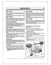
... power tool operation or when blowing dust. If environment is required. ■ Lubricatethehelght adjustmentleverand relatedhardware with light oil. ■ Remove the wheels and lubricate the surface of the axle bolt and the inner surface of grass and leaves on removing the blade. A WARNING: Always protect hands by their use identical replacement blades. ■ Stop the motor and remove the switch key. Remove any other material when performing blade maintenance. REPLACING THE CUTTING BLADE...
... power tool operation or when blowing dust. If environment is required. ■ Lubricatethehelght adjustmentleverand relatedhardware with light oil. ■ Remove the wheels and lubricate the surface of the axle bolt and the inner surface of grass and leaves on removing the blade. A WARNING: Always protect hands by their use identical replacement blades. ■ Stop the motor and remove the switch key. Remove any other material when performing blade maintenance. REPLACING THE CUTTING BLADE...

Operation Manual
Page 15
... the instructions in the Replacing the Cutting Blade section, remove the mower blade. DO NOT attempt to sharpen the blade while it is attached to keep the blade balanced. Failure to replace a bent or damaged blade could cause an accident resulting in which they were removed. ■ Torque the blade nut down toward the mower deck and not down using a torque wrench (not provided) to the mower, especially the motor. IN Using...
... the instructions in the Replacing the Cutting Blade section, remove the mower blade. DO NOT attempt to sharpen the blade while it is attached to keep the blade balanced. Failure to replace a bent or damaged blade could cause an accident resulting in which they were removed. ■ Torque the blade nut down toward the mower deck and not down using a torque wrench (not provided) to the mower, especially the motor. IN Using...
Operation Manual
Page 16
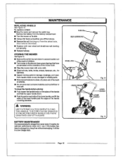
MAINTENANCE REPLACING WHEELS See Figure 13. To replace a wheel: ■ Stop the motor and remove the switch key. Have repairs made on its side. ■ Using a flat blade screwdriver, pry off the hubcap. ■ Remove the self-locking nut from the battery compartment ■ Turn the mower on its side and clean grass clippings that have accumulated on each side of the lower handle, and lift the sides of the...
MAINTENANCE REPLACING WHEELS See Figure 13. To replace a wheel: ■ Stop the motor and remove the switch key. Have repairs made on its side. ■ Using a flat blade screwdriver, pry off the hubcap. ■ Remove the self-locking nut from the battery compartment ■ Turn the mower on its side and clean grass clippings that have accumulated on each side of the lower handle, and lift the sides of the...
Operation Manual
Page 17
.... Solution Adjust the height of mower housing and blade dragging in heavy grass, or cutting height too low. Tighten handle knobs. Lawn is low in position. Bent motor shaft. Have repaired by grinding each cutting edge equally. Charge the battery. Mower not mulching properly. Raise cutting height. Handle knobs not tightened. take a charge. High grass, rear of the handle and make sure the carriage bolts are seated properly. TROUBLESHOOTING Problem Handle not in charge. height not set properly. Mower vibrating at higher speed. mowing. Blade is...
.... Solution Adjust the height of mower housing and blade dragging in heavy grass, or cutting height too low. Tighten handle knobs. Lawn is low in position. Bent motor shaft. Have repaired by grinding each cutting edge equally. Charge the battery. Mower not mulching properly. Raise cutting height. Handle knobs not tightened. take a charge. High grass, rear of the handle and make sure the carriage bolts are seated properly. TROUBLESHOOTING Problem Handle not in charge. height not set properly. Mower vibrating at higher speed. mowing. Blade is...
Operation Manual
Page 18
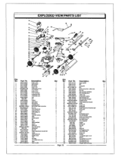
... battery assy right shutter left shutter motor vent self-tapping screw cover screw motor cover cover envelope connection wire connection wire cap nut washer fight wheel axle sleeve adjusting shim hex socket head cap screw hex nut front wheel axle front left wheel self-locking nut link bar extension spring deck spindle guard fan blade blade insulator spacer blade nut hex head screw spring pad hex nut height adjustment bracket left screw self-locking nut rubber board chip rear flap rear wheel...
... battery assy right shutter left shutter motor vent self-tapping screw cover screw motor cover cover envelope connection wire connection wire cap nut washer fight wheel axle sleeve adjusting shim hex socket head cap screw hex nut front wheel axle front left wheel self-locking nut link bar extension spring deck spindle guard fan blade blade insulator spacer blade nut hex head screw spring pad hex nut height adjustment bracket left screw self-locking nut rubber board chip rear flap rear wheel...
Operation Manual
Page 19
.... ■ Delivery, installation or normal adjustments explained in the operator's manual. ■ Damage or liability caused by shipping, improper handling, improper installation, incorrect voltage or improper wiring, improper maintenance, improper modification, or the use . ■ Cosmetic defects that become worn during normal use of accessories and/or attachments not specifically recommended. ■ Repairs necessary because of products or parts determined not to repair or replace under licensefromHomeliteConsumerProductsInc...
.... ■ Delivery, installation or normal adjustments explained in the operator's manual. ■ Damage or liability caused by shipping, improper handling, improper installation, incorrect voltage or improper wiring, improper maintenance, improper modification, or the use . ■ Cosmetic defects that become worn during normal use of accessories and/or attachments not specifically recommended. ■ Repairs necessary because of products or parts determined not to repair or replace under licensefromHomeliteConsumerProductsInc...
Operation Manual
Page 20
... housing. Please record the serial number in China MODEL NUMBER UT13110 SERIAL NUMBER HOMELITE CONSUMER PRODUCTS, INC. 1428 Pearman Dairy Road Anderson, SC 29625 www.homelite.com 987000-039 Made in the space provided below. Homelite OPERATOR'S MANUAL 17 in. 24 VOLT CORDLESS LAWN MOWER WITH 12 AMP HOUR BATTERY UT13110 SERVICE Forpartsorservice,contactyournearestHomeliteauthorized service dealer.Besuretoprovide all relevant information when you , please call or visit. REPAIR PARTS The model number...
... housing. Please record the serial number in China MODEL NUMBER UT13110 SERIAL NUMBER HOMELITE CONSUMER PRODUCTS, INC. 1428 Pearman Dairy Road Anderson, SC 29625 www.homelite.com 987000-039 Made in the space provided below. Homelite OPERATOR'S MANUAL 17 in. 24 VOLT CORDLESS LAWN MOWER WITH 12 AMP HOUR BATTERY UT13110 SERVICE Forpartsorservice,contactyournearestHomeliteauthorized service dealer.Besuretoprovide all relevant information when you , please call or visit. REPAIR PARTS The model number...

