

User Guide
Page 3
... this system. The user may find the following two conditions: 1. This is the responsibility of connecting cables and equipment other than those specified by Honeywell may void the FCC authorization to correct the interference by one or more of the following measures: &#... user is no guarantee that interference will not occur in a residential installation. If this equipment not expressly approved by Honeywell. Use only shielded data cables with cables less than 3 meters may not cause harmful interference. 2. UL Statement UL listed: UL60950-1, 2nd Edition. The correction...
... this system. The user may find the following two conditions: 1. This is the responsibility of connecting cables and equipment other than those specified by Honeywell may void the FCC authorization to correct the interference by one or more of the following measures: &#... user is no guarantee that interference will not occur in a residential installation. If this equipment not expressly approved by Honeywell. Use only shielded data cables with cables less than 3 meters may not cause harmful interference. 2. UL Statement UL listed: UL60950-1, 2nd Edition. The correction...

User Guide
Page 8
...the FCC authorization to operate this system. Caution: Any changes or modifications made to this equipment not expressly approved by Honeywell may cause undesired operation. Cables greater than 3 meters. UL Statement UL listed: UL60950-1, 2nd Edition.. This device may not cause interference. 2....Xenon 1902 and CCB01-010BT Base USA FCC Part 15 Subpart C This device complies with Canadian RSS-210. Use only shielded data cables with cables less than 3 meters may cause undesired operation. Son fonctionnement est assujetti aux conditions suivantes : 1. This device may not cause ...
...the FCC authorization to operate this system. Caution: Any changes or modifications made to this equipment not expressly approved by Honeywell may cause undesired operation. Cables greater than 3 meters. UL Statement UL listed: UL60950-1, 2nd Edition.. This device may not cause interference. 2....Xenon 1902 and CCB01-010BT Base USA FCC Part 15 Subpart C This device complies with Canadian RSS-210. Use only shielded data cables with cables less than 3 meters may cause undesired operation. Son fonctionnement est assujetti aux conditions suivantes : 1. This device may not cause ...

User Guide
Page 23
...-1 1902/1912 Scanner Product Specifications 12-2 CCB01-010BT Charge Base Product Specifications 12-3 Depth of Field Charts 12-4 CCB01-010BT Charge Base Mounting 12-7 Standard Cable Pinouts 12-8 ix Interface Keys Keyboard Function Relationships 9-1 Supported Interface Keys 9-3 Chapter 10 - Prefix to All Symbologies 10-1 Show Decoder Revision 10-1 Show Scan Driver...
...-1 1902/1912 Scanner Product Specifications 12-2 CCB01-010BT Charge Base Product Specifications 12-3 Depth of Field Charts 12-4 CCB01-010BT Charge Base Mounting 12-7 Standard Cable Pinouts 12-8 ix Interface Keys Keyboard Function Relationships 9-1 Supported Interface Keys 9-3 Chapter 10 - Prefix to All Symbologies 10-1 Show Decoder Revision 10-1 Show Scan Driver...

User Guide
Page 24
... Scanner 13-1 Cleaning the Window 13-1 Health Care Housing 13-1 Inspecting Cords and Connectors 13-2 Replacing Cables in Corded Scanners 13-2 Replacing an Interface Cable 13-3 Replacing Cables and Batteries in Cordless Systems 13-3 Replacing an Interface Cable in a Base 13-3 Changing a scanner Battery 13-4 Troubleshooting a Xenon Scanner 13-4 Troubleshooting a Cordless System 13-5 Troubleshooting...
... Scanner 13-1 Cleaning the Window 13-1 Health Care Housing 13-1 Inspecting Cords and Connectors 13-2 Replacing Cables in Corded Scanners 13-2 Replacing an Interface Cable 13-3 Replacing Cables and Batteries in Cordless Systems 13-3 Replacing an Interface Cable in a Base 13-3 Changing a scanner Battery 13-4 Troubleshooting a Xenon Scanner 13-4 Troubleshooting a Cordless System 13-5 Troubleshooting...
User Guide
Page 26
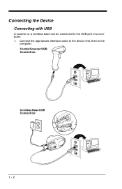
Corded Scanner USB Connection: Cordless Base USB Connection: 1 - 2 Connect the appropriate interface cable to the device first, then to the USB port of a computer. 1. Connecting the Device Connecting with USB A scanner or a cordless base can be connected to the computer.
Corded Scanner USB Connection: Cordless Base USB Connection: 1 - 2 Connect the appropriate interface cable to the device first, then to the USB port of a computer. 1. Connecting the Device Connecting with USB A scanner or a cordless base can be connected to the computer.
User Guide
Page 27
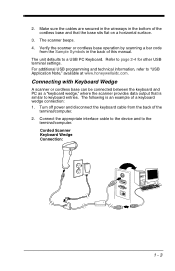
... PC Keyboard. Corded Scanner Keyboard Wedge Connection: 1 - 3 The following is similar to keyboard entries. Make sure the cables are secured in the wireways in the back of a keyboard wedge connection: 1. Connect the appropriate interface cable to the device and to page 2-4 for other USB terminal settings. Verify the scanner or cordless base... back of the cordless base and that is an example of this manual. Refer to the terminal/computer. 2. Turn off power and disconnect the keyboard cable from the Sample Symbols in the bottom of the terminal/computer. 2.
... PC Keyboard. Corded Scanner Keyboard Wedge Connection: 1 - 3 The following is similar to keyboard entries. Make sure the cables are secured in the wireways in the back of a keyboard wedge connection: 1. Connect the appropriate interface cable to the device and to page 2-4 for other USB terminal settings. Verify the scanner or cordless base... back of the cordless base and that is an example of this manual. Refer to the terminal/computer. 2. Turn off power and disconnect the keyboard cable from the Sample Symbols in the bottom of the terminal/computer. 2.

User Guide
Page 28
The scanner beeps. 5. Verify the scanner or cordless base operation by scanning a bar code from the Sample Symbols in the bottom of this manual. The scanner beeps once. Make sure the cables are secured in the wireways in the back of the cordless base and that the base sits flat on . A carriage return (CR) suffix is added to an IBM PC AT and compatibles keyboard wedge interface with a USA keyboard. The unit defaults to bar code data. 1 - 4 Cordless Base Keyboard Wedge Connection: 3. Turn the terminal/computer power back on a horizontal surface. 4.
The scanner beeps. 5. Verify the scanner or cordless base operation by scanning a bar code from the Sample Symbols in the bottom of this manual. The scanner beeps once. Make sure the cables are secured in the wireways in the back of the cordless base and that the base sits flat on . A carriage return (CR) suffix is added to an IBM PC AT and compatibles keyboard wedge interface with a USA keyboard. The unit defaults to bar code data. 1 - 4 Cordless Base Keyboard Wedge Connection: 3. Turn the terminal/computer power back on a horizontal surface. 4.

User Guide
Page 29
Connect the appropriate interface cable to work properly, you must have the correct cable for your type of terminal/computer. Corded Scanner RS232 Serial Port Connection: Cordless Base RS232 Serial Port Connection: 1 - 5 Connecting with RS232 Serial Port 1. Note: For the scanner or cordless base to the scanner. Turn off power to the terminal/computer. 2.
Connect the appropriate interface cable to work properly, you must have the correct cable for your type of terminal/computer. Corded Scanner RS232 Serial Port Connection: Cordless Base RS232 Serial Port Connection: 1 - 5 Connecting with RS232 Serial Port 1. Note: For the scanner or cordless base to the scanner. Turn off power to the terminal/computer. 2.

User Guide
Page 30
.... Tighten the two screws to secure the connector to the com- Plug the serial connector into the serial port on a horizontal surface. 4. 3. Make sure the cables are secured in the wireways in the bottom of the cordless base and that the base sits flat on your computer. Corded Scanner RS485 Connection...
.... Tighten the two screws to secure the connector to the com- Plug the serial connector into the serial port on a horizontal surface. 4. 3. Make sure the cables are secured in the wireways in the bottom of the cordless base and that the base sits flat on your computer. Corded Scanner RS485 Connection...

User Guide
Page 31
Cordless Base RS485 Connection: 2. For further RS485 settings, refer to RS485, page 2-2. 1 - 7 The scanner beeps. 4. Turn the terminal/computer power back on a horizontal surface. 3. Verify the scanner or cordless base operation by scanning a bar code from the Sample Symbols in the bottom of this manual. The scanner beeps once. Make sure the cables are secured in the wireways in the back of the cordless base and that the base sits flat on .
Cordless Base RS485 Connection: 2. For further RS485 settings, refer to RS485, page 2-2. 1 - 7 The scanner beeps. 4. Turn the terminal/computer power back on a horizontal surface. 3. Verify the scanner or cordless base operation by scanning a bar code from the Sample Symbols in the bottom of this manual. The scanner beeps once. Make sure the cables are secured in the wireways in the back of the cordless base and that the base sits flat on .

User Guide
Page 62
Linking the Scanner to an Access Point Turn on the computer. Plug the interface cable into the Access Point first and then into the appropriate port on the computer (laptop/desktop). The scanner emits a short beep and flashes the green ...
Linking the Scanner to an Access Point Turn on the computer. Plug the interface cable into the Access Point first and then into the appropriate port on the computer (laptop/desktop). The scanner emits a short beep and flashes the green ...
User Guide
Page 65
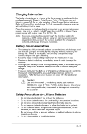
... without impacting the battery life. Refer to Charge Only Mode (page 3-12) if you are powering the base through the interface cable (for example, a USB cable) and not using an external power supply plugged into the aux port, the current available for charging is reduced and charge times...is working properly, send it will eventually be charged without fully discharging, without a full charge, and can be recharged many times, it to Honeywell International Inc. Charging Information The battery is designed to charge while the scanner is positioned in fire or heat the batteries. • Do ...
... without impacting the battery life. Refer to Charge Only Mode (page 3-12) if you are powering the base through the interface cable (for example, a USB cable) and not using an external power supply plugged into the aux port, the current available for charging is reduced and charge times...is working properly, send it will eventually be charged without fully discharging, without a full charge, and can be recharged many times, it to Honeywell International Inc. Charging Information The battery is designed to charge while the scanner is positioned in fire or heat the batteries. • Do ...

User Guide
Page 233
... connected to your device in order for a scanner. Application Plug-Ins (Apps) Any apps that you are using the serial port and RS232 cable, an external power supply is required. To communicate with a scanner, EZConfig-Scanning requires that contains all your apps. * Decoding Apps On Decoding... the PC have at least one available serial communication port, or a serial port emulation using a USB serial port emulation, only a USB cable is required. Using EZConfig-Scanning, you can even save/open the programming parameters for the apps setting to load in groups: Decoding, and ...
... connected to your device in order for a scanner. Application Plug-Ins (Apps) Any apps that you are using the serial port and RS232 cable, an external power supply is required. To communicate with a scanner, EZConfig-Scanning requires that contains all your apps. * Decoding Apps On Decoding... the PC have at least one available serial communication port, or a serial port emulation using a USB serial port emulation, only a USB cable is required. Using EZConfig-Scanning, you can even save/open the programming parameters for the apps setting to load in groups: Decoding, and ...

User Guide
Page 287
Use of a cable with Honeywell legacy products. Use of any cables not provided by your warranty. Standard Cable Pinouts Keyboard Wedge 12 - 9 10 Pin RJ41 Modular Plug connects to the base 1 Cable shield 2 Cable select 3 Supply ground 4 Terminal data 5 Terminal clock 6 Keyboard clock 7 Supply power input +5V power 8 Keyboard data 9 10 Note: Pin assignments are not compatible with improper pin assignments may result in damage not covered by the manufacturer may lead to damage to the unit.
Use of a cable with Honeywell legacy products. Use of any cables not provided by your warranty. Standard Cable Pinouts Keyboard Wedge 12 - 9 10 Pin RJ41 Modular Plug connects to the base 1 Cable shield 2 Cable select 3 Supply ground 4 Terminal data 5 Terminal clock 6 Keyboard clock 7 Supply power input +5V power 8 Keyboard data 9 10 Note: Pin assignments are not compatible with improper pin assignments may result in damage not covered by the manufacturer may lead to damage to the unit.

User Guide
Page 288
Standard Cable Pinouts Serial Output 12 - 10 10 Pin RJ41 Modular Plug connects to the unit. Use of a cable with Honeywell legacy products. Use of any cables not provided by the manufacturer may lead to damage to the base 1 Cable shield 2 Cable select 3 Supply ground 4 Transmit data 5 Receive data - serial data to scanner 6 CTS 7 +5V power 8 RTS 9 10 Note: Pin assignments are not compatible with improper pin assignments may result in damage not covered by your warranty.
Standard Cable Pinouts Serial Output 12 - 10 10 Pin RJ41 Modular Plug connects to the unit. Use of a cable with Honeywell legacy products. Use of any cables not provided by the manufacturer may lead to damage to the base 1 Cable shield 2 Cable select 3 Supply ground 4 Transmit data 5 Receive data - serial data to scanner 6 CTS 7 +5V power 8 RTS 9 10 Note: Pin assignments are not compatible with improper pin assignments may result in damage not covered by your warranty.

User Guide
Page 289
Use of any cables not provided by your warranty. Use of a cable with Honeywell legacy products. serial data to scanner 6 7 +5V power 8 Transmit Enable 9 10 Note: RS485 signal conversion is performed in damage not covered by the manufacturer may lead to damage to the base 1 Cable shield 2 Cable select 3 Supply ground 4 Transmit data 5 Receive data - Standard Cable Pinouts RS485 Output 12 - 11 10 Pin RJ41 Modular Plug connects to the unit. Pin assignments are not compatible with improper pin assignments may result in the cable.
Use of any cables not provided by your warranty. Use of a cable with Honeywell legacy products. serial data to scanner 6 7 +5V power 8 Transmit Enable 9 10 Note: RS485 signal conversion is performed in damage not covered by the manufacturer may lead to damage to the base 1 Cable shield 2 Cable select 3 Supply ground 4 Transmit data 5 Receive data - Standard Cable Pinouts RS485 Output 12 - 11 10 Pin RJ41 Modular Plug connects to the unit. Pin assignments are not compatible with improper pin assignments may result in the cable.

User Guide
Page 290
Use of a cable with Honeywell legacy products. Standard Cable Pinouts USB 12 - 12 10 Pin Modular Plug connects to the unit. Note: Pin assignments are not compatible with improper pin assignments may result in damage not covered by the manufacturer may lead to damage to the base 1 Cable shield 2 Cable select 3 Supply ground 4 5 6 7 +5V power 8 9 Data + 10 Data - Use of any cables not provided by your warranty.
Use of a cable with Honeywell legacy products. Standard Cable Pinouts USB 12 - 12 10 Pin Modular Plug connects to the unit. Note: Pin assignments are not compatible with improper pin assignments may result in damage not covered by the manufacturer may lead to damage to the base 1 Cable shield 2 Cable select 3 Supply ground 4 5 6 7 +5V power 8 9 Data + 10 Data - Use of any cables not provided by your warranty.

User Guide
Page 292
... be covered by a flexible retention tab. They are on page 13-2. A badly worn cable or damaged connector may not be field replaceable. • Order replacement cables from Honeywell or from an authorized distributor. • When ordering a replacement cable, specify the cable part number of damage. When properly seated, the connector is attached to assure safe...
... be covered by a flexible retention tab. They are on page 13-2. A badly worn cable or damaged connector may not be field replaceable. • Order replacement cables from Honeywell or from an authorized distributor. • When ordering a replacement cable, specify the cable part number of damage. When properly seated, the connector is attached to assure safe...

User Guide
Page 293
...tab, releasing the connector. Insert the connector into place. 13 - 3 Replace with the new cable. Turn the power to the host system OFF. 2. Replace with the new cable. Disconnect the base's cable from the terminal or computer. 3. Locate the small hole on the connector release clip. 5.... the opening and press firmly. Insert the connector into the small hole and press in a Base 1. Replacing Cables and Batteries in Cordless Systems Replacing an Interface Cable in . Pull the connector out while maintaining pressure on the paper clip, then remove the paper clip...
...tab, releasing the connector. Insert the connector into place. 13 - 3 Replace with the new cable. Turn the power to the host system OFF. 2. Replace with the new cable. Disconnect the base's cable from the terminal or computer. 3. Locate the small hole on the connector release clip. 5.... the opening and press firmly. Insert the connector into the small hole and press in a Base 1. Replacing Cables and Batteries in Cordless Systems Replacing an Interface Cable in . Pull the connector out while maintaining pressure on the paper clip, then remove the paper clip...

User Guide
Page 294
... in the scanner or in the decoder to enter the data into your application. If the scanner isn't reading symbols well, check that : • The cable is connected properly. • The host system power is displayed on the host device correctly, but not entered? Is the power on the end cap...
... in the scanner or in the decoder to enter the data into your application. If the scanner isn't reading symbols well, check that : • The cable is connected properly. • The host system power is displayed on the host device correctly, but not entered? Is the power on the end cap...
