

User Guide
Page 3
... find the following booklet helpful: "Something About Interference." These limits are designed to operate this equipment not expressly approved by Honeywell. Operation is subject to which can radiate radio frequency energy and, if not installed and used in a particular installation. This...television reception, which the receiver is the responsibility of connecting cables and equipment other than those specified by Honeywell may cause harmful interference to part 15 of the FCC Rules. Use only shielded data cables with the limits for additional suggestions. UL Statement UL ...
... find the following booklet helpful: "Something About Interference." These limits are designed to operate this equipment not expressly approved by Honeywell. Operation is subject to which can radiate radio frequency energy and, if not installed and used in a particular installation. This...television reception, which the receiver is the responsibility of connecting cables and equipment other than those specified by Honeywell may cause harmful interference to part 15 of the FCC Rules. Use only shielded data cables with the limits for additional suggestions. UL Statement UL ...
User Guide
Page 21
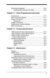
... 13 - Maintenance Repairs 13-1 Maintenance 13-1 Cleaning the Device 13-1 Inspecting Cords and Connectors 13-1 Replacing Cables in Corded Scanners 13-1 Replacing an Interface Cable 13-2 Replacing Cables and Batteries in Cordless Systems 13-2 Replacing an Interface Cable in a Base 13-2 Changing a scanner Battery 13-3 Troubleshooting a Xenon Scanner 13-3 ix Serial Programming Commands Conventions...
... 13 - Maintenance Repairs 13-1 Maintenance 13-1 Cleaning the Device 13-1 Inspecting Cords and Connectors 13-1 Replacing Cables in Corded Scanners 13-1 Replacing an Interface Cable 13-2 Replacing Cables and Batteries in Cordless Systems 13-2 Replacing an Interface Cable in a Base 13-2 Changing a scanner Battery 13-3 Troubleshooting a Xenon Scanner 13-3 ix Serial Programming Commands Conventions...
User Guide
Page 24
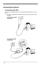
Connecting the Device Connecting with USB A scanner or a cordless base can be connected to the computer. Corded Scanner USB Connection: Cordless Base USB Connection: 1 - 2 Connect the appropriate interface cable to the device first, then to the USB port of a computer. 1.
Connecting the Device Connecting with USB A scanner or a cordless base can be connected to the computer. Corded Scanner USB Connection: Cordless Base USB Connection: 1 - 2 Connect the appropriate interface cable to the device first, then to the USB port of a computer. 1.

User Guide
Page 25
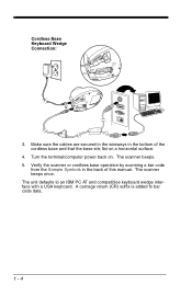
... wedge," plugged into the serial port, or connected to a portable data terminal in the bottom of this manual. Turn off power and disconnect the keyboard cable from the Sample Symbols in the back of the cordless base and that the base sits flat on a horizontal surface. 3. The unit defaults to "USB... the scanner or cordless base operation by scanning a bar code from the back of a keyboard wedge connection: 1. Refer to the terminal/computer. Make sure the cables are secured in the wireways in wand emulation or non decoded output mode. Connect the appropriate interface...
... wedge," plugged into the serial port, or connected to a portable data terminal in the bottom of this manual. Turn off power and disconnect the keyboard cable from the Sample Symbols in the back of the cordless base and that the base sits flat on a horizontal surface. 3. The unit defaults to "USB... the scanner or cordless base operation by scanning a bar code from the back of a keyboard wedge connection: 1. Refer to the terminal/computer. Make sure the cables are secured in the wireways in wand emulation or non decoded output mode. Connect the appropriate interface...
User Guide
Page 26
Verify the scanner or cordless base operation by scanning a bar code from the Sample Symbols in the bottom of this manual. The scanner beeps. 5. The unit defaults to bar code data. 1 - 4 Turn the terminal/computer power back on a horizontal surface. 4. A carriage return (CR) suffix is added to an IBM PC AT and compatibles keyboard wedge interface with a USA keyboard. Cordless Base Keyboard Wedge Connection: 3. Make sure the cables are secured in the wireways in the back of the cordless base and that the base sits flat on . The scanner beeps once.
Verify the scanner or cordless base operation by scanning a bar code from the Sample Symbols in the bottom of this manual. The scanner beeps. 5. The unit defaults to bar code data. 1 - 4 Turn the terminal/computer power back on a horizontal surface. 4. A carriage return (CR) suffix is added to an IBM PC AT and compatibles keyboard wedge interface with a USA keyboard. Cordless Base Keyboard Wedge Connection: 3. Make sure the cables are secured in the wireways in the back of the cordless base and that the base sits flat on . The scanner beeps once.

User Guide
Page 27
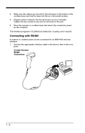
Turn off power to the scanner. Corded Scanner RS232 Serial Port Connection: Cordless Base RS232 Serial Port Connection: 1 - 5 Connect the appropriate interface cable to the terminal/computer. 2. Connecting with RS232 Serial Port 1. Note: For the scanner or cordless base to work properly, you must have the correct cable for your type of terminal/computer.
Turn off power to the scanner. Corded Scanner RS232 Serial Port Connection: Cordless Base RS232 Serial Port Connection: 1 - 5 Connect the appropriate interface cable to the terminal/computer. 2. Connecting with RS232 Serial Port 1. Note: For the scanner or cordless base to work properly, you must have the correct cable for your type of terminal/computer.
User Guide
Page 28
puter. Corded Scanner RS485 Connection: 1 - 6 Make sure the cables are secured in the wireways in the bottom of the cordless base and that the base sits flat on your computer. Plug the serial connector ... be connected for an IBM POS terminal interface. 1. This interface programs 115,200 baud, 8 data bits, no parity, and 1 stop bit. Connect the appropriate interface cable to the device, then to the port. 5. Once the scanner or cordless base has been fully connected, power up the computer. Tighten the two screws...
puter. Corded Scanner RS485 Connection: 1 - 6 Make sure the cables are secured in the wireways in the bottom of the cordless base and that the base sits flat on your computer. Plug the serial connector ... be connected for an IBM POS terminal interface. 1. This interface programs 115,200 baud, 8 data bits, no parity, and 1 stop bit. Connect the appropriate interface cable to the device, then to the port. 5. Once the scanner or cordless base has been fully connected, power up the computer. Tighten the two screws...

User Guide
Page 29
Verify the scanner or cordless base operation by scanning a bar code from the Sample Symbols in the bottom of this manual. Turn the terminal/computer power back on a horizontal surface. 3. Cordless Base RS485 Connection: 2. Make sure the cables are secured in the wireways in the back of the cordless base and that the base sits flat on . For further RS485 settings, refer to RS485, page 2-2.. 1 - 7 The scanner beeps. 4. The scanner beeps once.
Verify the scanner or cordless base operation by scanning a bar code from the Sample Symbols in the bottom of this manual. Turn the terminal/computer power back on a horizontal surface. 3. Cordless Base RS485 Connection: 2. Make sure the cables are secured in the wireways in the back of the cordless base and that the base sits flat on . For further RS485 settings, refer to RS485, page 2-2.. 1 - 7 The scanner beeps. 4. The scanner beeps once.
User Guide
Page 62
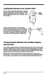
.... This is sent to the host system via the base or Access Point. If it cannot be determined that the data has 3 - 2 Plug the interface cable into the Access Point first and then into the appropriate port on the computer (laptop/desktop). Communication Between the Cordless System and the Host The...
.... This is sent to the host system via the base or Access Point. If it cannot be determined that the data has 3 - 2 Plug the interface cable into the Access Point first and then into the appropriate port on the computer (laptop/desktop). Communication Between the Cordless System and the Host The...

User Guide
Page 65
...Mode (page 3-11) if you are powering the base through the interface cable (for example, a USB cable) and not using an external power supply plugged into the aux port, the current available for an interpretation of any non-Honeywell battery may result in use. • Replace a defective battery immediately ...base. There is no need to perform any metal object. • Do not pierce, strike or step on batteries or subject batteries to Honeywell International Inc. Refer to Base/Access Point LED Sequences and Meaning, page 3-7, for charging is not in damage not covered by the warranty....
...Mode (page 3-11) if you are powering the base through the interface cable (for example, a USB cable) and not using an external power supply plugged into the aux port, the current available for an interpretation of any non-Honeywell battery may result in use. • Replace a defective battery immediately ...base. There is no need to perform any metal object. • Do not pierce, strike or step on batteries or subject batteries to Honeywell International Inc. Refer to Base/Access Point LED Sequences and Meaning, page 3-7, for charging is not in damage not covered by the warranty....

User Guide
Page 224
...the image settings and save the image settings to an INI file, which can be saved to files in an image window. Access the Honeywell web site at least one of the scanner. Click on Xenon. 4. Click on the Resources tab. EZConfig Operations The EZConfig software performs...you to capture new images. When one available serial communication port, or a serial port emulation using a USB serial port emulation, only a USB cable is grouped into different categories. The "Configure" tree option has all the image-related functions that particular category. Images captured from the Web Note...
...the image settings and save the image settings to an INI file, which can be saved to files in an image window. Access the Honeywell web site at least one of the scanner. Click on Xenon. 4. Click on the Resources tab. EZConfig Operations The EZConfig software performs...you to capture new images. When one available serial communication port, or a serial port emulation using a USB serial port emulation, only a USB cable is grouped into different categories. The "Configure" tree option has all the image-related functions that particular category. Images captured from the Web Note...

User Guide
Page 270
Use of any cables not provided by the manufacturer may lead to damage to the unit. Use of a cable with Honeywell legacy products. Standard Cable Pinouts Keyboard Wedge 12 - 4 10 Pin RJ41 Modular Plug connects to the base 1 Cable shield 2 Cable select 3 Supply ground 4 Terminal data 5 Terminal clock 6 Keyboard clock 7 Supply power input +5V power 8 Keyboard data 9 10 Note: Pin assignments are not compatible with improper pin assignments may result in damage not covered by your warranty.
Use of any cables not provided by the manufacturer may lead to damage to the unit. Use of a cable with Honeywell legacy products. Standard Cable Pinouts Keyboard Wedge 12 - 4 10 Pin RJ41 Modular Plug connects to the base 1 Cable shield 2 Cable select 3 Supply ground 4 Terminal data 5 Terminal clock 6 Keyboard clock 7 Supply power input +5V power 8 Keyboard data 9 10 Note: Pin assignments are not compatible with improper pin assignments may result in damage not covered by your warranty.
User Guide
Page 271
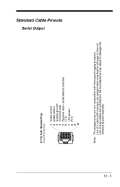
Use of a cable with Honeywell legacy products. Use of any cables not provided by your warranty. Standard Cable Pinouts Serial Output 12 - 5 10 Pin RJ41 Modular Plug connects to the unit. serial data to scanner 6 CTS 7 +5V power 8 RTS 9 10 Note: Pin assignments are not compatible with improper pin assignments may result in damage not covered by the manufacturer may lead to damage to the base 1 Cable shield 2 Cable select 3 Supply ground 4 Transmit data 5 Receive data -
Use of a cable with Honeywell legacy products. Use of any cables not provided by your warranty. Standard Cable Pinouts Serial Output 12 - 5 10 Pin RJ41 Modular Plug connects to the unit. serial data to scanner 6 CTS 7 +5V power 8 RTS 9 10 Note: Pin assignments are not compatible with improper pin assignments may result in damage not covered by the manufacturer may lead to damage to the base 1 Cable shield 2 Cable select 3 Supply ground 4 Transmit data 5 Receive data -
User Guide
Page 272
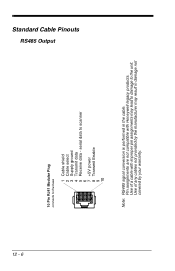
serial data to scanner 6 7 +5V power 8 Transmit Enable 9 10 Note: RS485 signal conversion is performed in damage not covered by the manufacturer may lead to damage to the base 1 Cable shield 2 Cable select 3 Supply ground 4 Transmit data 5 Receive data - Pin assignments are not compatible with improper pin assignments may result in the cable. Use of any cables not provided by your warranty. Standard Cable Pinouts RS485 Output 12 - 6 10 Pin RJ41 Modular Plug connects to the unit. Use of a cable with Honeywell legacy products.
serial data to scanner 6 7 +5V power 8 Transmit Enable 9 10 Note: RS485 signal conversion is performed in damage not covered by the manufacturer may lead to damage to the base 1 Cable shield 2 Cable select 3 Supply ground 4 Transmit data 5 Receive data - Pin assignments are not compatible with improper pin assignments may result in the cable. Use of any cables not provided by your warranty. Standard Cable Pinouts RS485 Output 12 - 6 10 Pin RJ41 Modular Plug connects to the unit. Use of a cable with Honeywell legacy products.
User Guide
Page 273
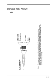
Use of any cables not provided by the manufacturer may lead to damage to the base 1 Cable shield 2 Cable select 3 Supply ground 4 5 6 7 +5V power 8 9 Data + 10 Data - Use of a cable with Honeywell legacy products. Standard Cable Pinouts USB 12 - 7 10 Pin Modular Plug connects to the unit. Note: Pin assignments are not compatible with improper pin assignments may result in damage not covered by your warranty.
Use of any cables not provided by the manufacturer may lead to damage to the base 1 Cable shield 2 Cable select 3 Supply ground 4 5 6 7 +5V power 8 9 Data + 10 Data - Use of a cable with Honeywell legacy products. Standard Cable Pinouts USB 12 - 7 10 Pin Modular Plug connects to the unit. Note: Pin assignments are not compatible with improper pin assignments may result in damage not covered by your warranty.
User Guide
Page 275
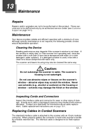
...not to be performed on this product. Although specific maintenance is not clean. Inspecting Cords and Connectors Inspect the interface cable and connector for information about cable replacement. Contact your distributor for wear or other signs of care. If the window is not watertight. The scanner and...scanner isn't operating well, clean the window with a soft cloth or lens tissue dampened with water (or a mild detergent- The interface cable is attached to the scanner with water only. 13 Maintenance Repairs Repairs and/or upgrades are to be performed only by a flexible retention tab...
...not to be performed on this product. Although specific maintenance is not clean. Inspecting Cords and Connectors Inspect the interface cable and connector for information about cable replacement. Contact your distributor for wear or other signs of care. If the window is not watertight. The scanner and...scanner isn't operating well, clean the window with a soft cloth or lens tissue dampened with water (or a mild detergent- The interface cable is attached to the scanner with water only. 13 Maintenance Repairs Repairs and/or upgrades are to be performed only by a flexible retention tab...
User Guide
Page 276
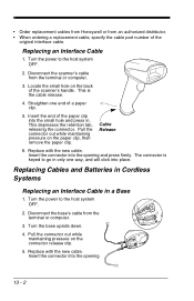
.... 3. Turn the base upside down. 4. Replace with the new cable. This depresses the retention tab, releasing the connector. • Order replacement cables from Honeywell or from an authorized distributor. • When ordering a replacement cable, specify the cable part number of a paper clip. 5. The connector is the cable release. 4. Turn the power to the host system OFF...
.... 3. Turn the base upside down. 4. Replace with the new cable. This depresses the retention tab, releasing the connector. • Order replacement cables from Honeywell or from an authorized distributor. • When ordering a replacement cable, specify the cable part number of a paper clip. 5. The connector is the cable release. 4. Turn the power to the host system OFF...

User Guide
Page 277
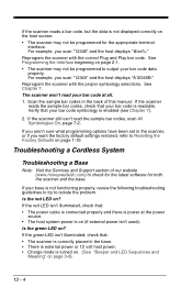
... in the scanner or in only one way, and will click into your application. If the scanner isn't reading symbols well, check that : • The cable is connected properly. • The host system power is not functioning properly, review the following Troubleshooting Guide to try to enter the data into place...
... in the scanner or in only one way, and will click into your application. If the scanner isn't reading symbols well, check that : • The cable is connected properly. • The host system power is not functioning properly, review the following Troubleshooting Guide to try to enter the data into place...
User Guide
Page 278
... external power isn't used). See Programming the Interface beginning on ? For example, you scan "12345" and the host displays "@es%." Verify that : • The power cable is connected properly and there is power at all. 1. If your bar code at the power source. • The host system power is not functioning...
... external power isn't used). See Programming the Interface beginning on ? For example, you scan "12345" and the host displays "@es%." Verify that : • The power cable is connected properly and there is power at all. 1. If your bar code at the power source. • The host system power is not functioning...

User Guide
Page 284
This includes but is five (5) years. HII extends these warranties only to : cables, power supplies, cradles, and docking stations. HAVE BEEN ADVISED OF THE POSSIBILITY OF SUCH INJURIES, LOSSES, OR DAMAGES. The duration of the limited warranty for ...
This includes but is five (5) years. HII extends these warranties only to : cables, power supplies, cradles, and docking stations. HAVE BEEN ADVISED OF THE POSSIBILITY OF SUCH INJURIES, LOSSES, OR DAMAGES. The duration of the limited warranty for ...
