User Manual
Page 3
... RS232 or Light Pen 7 RS485 or OCIA 8 Keyboard Wedge 9 Stand-Alone Keyboard Wedge 10 Full Speed or Low Speed USB (Integrated 11 EAS Deactivation 12 Scanner Operation The Scan Pattern Mode Select Button 13 How to Use CodeGate and the Manual Activation Mode 14 Indicators Audible ...15 Visual ...16 Failure ...17...
... RS232 or Light Pen 7 RS485 or OCIA 8 Keyboard Wedge 9 Stand-Alone Keyboard Wedge 10 Full Speed or Low Speed USB (Integrated 11 EAS Deactivation 12 Scanner Operation The Scan Pattern Mode Select Button 13 How to Use CodeGate and the Manual Activation Mode 14 Indicators Audible ...15 Visual ...16 Failure ...17...

User Manual
Page 4
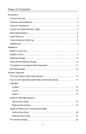
TABLE OF CONTENTS Troubleshooting Guide 23 Design Specifications 27 Applications and Protocols 29 Default Settings - Communication Parameters 30 Configuration Modes 35 Bar Codes 35 MetroSet2 35 Serial Configuration 35 Upgrading the Firmware 36 Scanner and Cable Terminations 37 Regulatory Compliance 41 Limited Warranty 44 Patents ...45 Index ...46 Contact Information and Office Locations 48 iii
TABLE OF CONTENTS Troubleshooting Guide 23 Design Specifications 27 Applications and Protocols 29 Default Settings - Communication Parameters 30 Configuration Modes 35 Bar Codes 35 MetroSet2 35 Serial Configuration 35 Upgrading the Firmware 36 Scanner and Cable Terminations 37 Regulatory Compliance 41 Limited Warranty 44 Patents ...45 Index ...46 Contact Information and Office Locations 48 iii

User Manual
Page 5
... • Firmware updates are easily loaded into Flash memory • OPOS and JPOS System Compatible • CodeGate® • Sunrise 2005 Compliant SCANNER MS3780-9 MS3780-11 MS3780-38 MS3780-40 INTERFACE OCIA and RS232 Transmit/Receive RS485S and Full RS232 RS232 Low Speed USB*, Keyboard Emulation Mode or... USB and RS232 Transmit/Receive with optional single-line scanning capabilities. The default setting is a hand-held, omnidirectional bar code scanner with EAS * Configurable for IBM® Host applications. 1 INTRODUCTION The MS3780 Fusion® is Keyboard Emulation Mode.
... • Firmware updates are easily loaded into Flash memory • OPOS and JPOS System Compatible • CodeGate® • Sunrise 2005 Compliant SCANNER MS3780-9 MS3780-11 MS3780-38 MS3780-40 INTERFACE OCIA and RS232 Transmit/Receive RS485S and Full RS232 RS232 Low Speed USB*, Keyboard Emulation Mode or... USB and RS232 Transmit/Receive with optional single-line scanning capabilities. The default setting is a hand-held, omnidirectional bar code scanner with EAS * Configurable for IBM® Host applications. 1 INTRODUCTION The MS3780 Fusion® is Keyboard Emulation Mode.

User Manual
Page 6
...to +5.2VDC For IBM Applications Other items may be ordered for download at 1-800-436-3876. 2 OPTIONAL ACCESSORIES Part No. INTRODUCTION Scanner and Accessories Part No. Regulated 5.2VDC @ 1A output. 46-00525 90VAC - 255VAC United States, Canada and Japan 46-00526 ...-3MPC-IB9 Metrologic Voltage Converter Cable, ±12VDC to DC Power Transformer - MS3780 00-02099 00-02407 BASIC KIT COMPONENTS Description Fusion Scanner MS3780 Installation and User's Guide * MetroSelect® Configuration Guide * * Guides also available for the specific protocol being used. To order...
...to +5.2VDC For IBM Applications Other items may be ordered for download at 1-800-436-3876. 2 OPTIONAL ACCESSORIES Part No. INTRODUCTION Scanner and Accessories Part No. Regulated 5.2VDC @ 1A output. 46-00525 90VAC - 255VAC United States, Canada and Japan 46-00526 ...-3MPC-IB9 Metrologic Voltage Converter Cable, ±12VDC to DC Power Transformer - MS3780 00-02099 00-02407 BASIC KIT COMPONENTS Description Fusion Scanner MS3780 Installation and User's Guide * MetroSelect® Configuration Guide * * Guides also available for the specific protocol being used. To order...

User Manual
Page 7
... order additional items, contact the dealer, distributor or call Metrologic's customer service department at 1-800-436-3876. S Applicable for the specific protocol being used. INTRODUCTION Scanner and Accessories Part No. MVC-3MNC-N7052 53-53213x-N-3 53-53214x-N-3 OPTIONAL ACCESSORIES Description Metrologic Voltage Converter Cable, ±12VDC to +5.2VDC For OCIA Applications...
... order additional items, contact the dealer, distributor or call Metrologic's customer service department at 1-800-436-3876. S Applicable for the specific protocol being used. INTRODUCTION Scanner and Accessories Part No. MVC-3MNC-N7052 53-53213x-N-3 53-53214x-N-3 OPTIONAL ACCESSORIES Description Metrologic Voltage Converter Cable, ±12VDC to +5.2VDC For OCIA Applications...
User Manual
Page 8
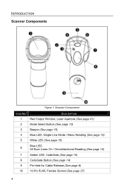
Scanner Components ITEM NO. DESCRIPTION 1 Red Output Window, Laser Aperture (See page 41) 2 Mode Select Button (See page 13) 3 Beeper (See page 15) 4 Blue LED, Single-Line Mode / Menu Reading (See page 15) 5 White LED (See page 15) 6 Blue LED, All Scan Lines On / Omnidirectional Reading (See page 15) 7 Amber LED, CodeGate (See page 15) 8 CodeGate Button (See page 14) 9 Pin Hole for Cable Release (See page 6) 10 10-Pin RJ45, Female Socket (See page 37) 4 INTRODUCTION Scanner Components Figure 1.
Scanner Components ITEM NO. DESCRIPTION 1 Red Output Window, Laser Aperture (See page 41) 2 Mode Select Button (See page 13) 3 Beeper (See page 15) 4 Blue LED, Single-Line Mode / Menu Reading (See page 15) 5 White LED (See page 15) 6 Blue LED, All Scan Lines On / Omnidirectional Reading (See page 15) 7 Amber LED, CodeGate (See page 15) 8 CodeGate Button (See page 14) 9 Pin Hole for Cable Release (See page 6) 10 10-Pin RJ45, Female Socket (See page 37) 4 INTRODUCTION Scanner Components Figure 1.

User Manual
Page 9
Caution and Serial Labels Caution: To maintain compliance with standard CSA C22.2 No. 60950-1/UL 60950-1 and norm EN/IEC 60950-1, the power source should meet the requirements for SELV (Safety Extra Low Voltage) according to the scanner must meet applicable performance requirements for a limited power source. Stand Specifications Figure 3. Stand Specifications 5 INTRODUCTION Caution and Serial Number Labels Figure 2. To maintain compliance with applicable standards, all circuits connected to EN/IEC 60950-1.
Caution and Serial Labels Caution: To maintain compliance with standard CSA C22.2 No. 60950-1/UL 60950-1 and norm EN/IEC 60950-1, the power source should meet the requirements for SELV (Safety Extra Low Voltage) according to the scanner must meet applicable performance requirements for a limited power source. Stand Specifications Figure 3. Stand Specifications 5 INTRODUCTION Caution and Serial Number Labels Figure 2. To maintain compliance with applicable standards, all circuits connected to EN/IEC 60950-1.

User Manual
Page 10
... cable. If the unit's case requires cleaning, use only a mild glass cleaner containing no ammonia. Figure 5. 6 Figure 6. Cable Removal Disconnect the power supply from the scanner. 1. Bend an ordinary paperclip into the small 'pin-hole'. INTRODUCTION Maintenance Smudges and dirt on the front side of the...
... cable. If the unit's case requires cleaning, use only a mild glass cleaner containing no ammonia. Figure 5. 6 Figure 6. Cable Removal Disconnect the power supply from the scanner. 1. Bend an ordinary paperclip into the small 'pin-hole'. INTRODUCTION Maintenance Smudges and dirt on the front side of the...

User Manual
Page 11
... will emit one beep. Check the AC input requirements of the PowerLink cable to make sure the voltage matches the AC outlet. When the scanner first receives power the white LED will flash, one blue LED will turn on the host device. 4. INSTALLATION RS232 or Light Pen 1.... Figure 7. Connect the 9-pin female end of the power supply to the appropriate communication port on and the scanner will appear at the PC. A software driver and correct configuration setting are also required for proper communication to the transformer. 6. The outlet must ...
... will emit one beep. Check the AC input requirements of the PowerLink cable to make sure the voltage matches the AC outlet. When the scanner first receives power the white LED will flash, one blue LED will turn on the host device. 4. INSTALLATION RS232 or Light Pen 1.... Figure 7. Connect the 9-pin female end of the power supply to the appropriate communication port on and the scanner will appear at the PC. A software driver and correct configuration setting are also required for proper communication to the transformer. 6. The outlet must ...

User Manual
Page 12
...MVC cable to Port 9 of the MVC cable into the serial port of the MVC cable to occur. Plugging the scanner into the 10-pin socket on and the scanner will appear at the PC. S Applicable for proper communication to the appropriate communication port on the host device. 4.... device. A software driver and correct configuration setting are also required for IBM® Host applications. 8 RS485 (above), OCIA (below) When the scanner first receives power the white LED will flash, one beep. For RS485: Connect the other end of the PC does not guarantee that scanned information...
...MVC cable to Port 9 of the MVC cable into the serial port of the MVC cable to occur. Plugging the scanner into the 10-pin socket on and the scanner will appear at the PC. S Applicable for proper communication to the appropriate communication port on the host device. 4.... device. A software driver and correct configuration setting are also required for IBM® Host applications. 8 RS485 (above), OCIA (below) When the scanner first receives power the white LED will flash, one beep. For RS485: Connect the other end of the PC does not guarantee that scanned information...

User Manual
Page 13
...port. If necessary use the male/female adapter cable supplied with the operation of the PowerLink cable into the power jack on and the scanner will turn on the PowerLink cable. The outlet must be located near the equipment and be easily accessible. For this reason, Metrologic ... contact a Metrologic customer service representative. See Caution statement on the host device. INSTALLATION Keyboard Wedge 1. Turn off the host device. 2. When the scanner first receives power the white LED will flash, one blue LED will emit one beep. Plug the male 10-pin RJ45 end of the...
...port. If necessary use the male/female adapter cable supplied with the operation of the PowerLink cable into the power jack on and the scanner will turn on the PowerLink cable. The outlet must be located near the equipment and be easily accessible. For this reason, Metrologic ... contact a Metrologic customer service representative. See Caution statement on the host device. INSTALLATION Keyboard Wedge 1. Turn off the host device. 2. When the scanner first receives power the white LED will flash, one blue LED will emit one beep. Plug the male 10-pin RJ45 end of the...

User Manual
Page 14
... Metrologic recommends using an external power supply. Check the AC input requirements of the PowerLink cable to the keyboard port on and the scanner will emit one beep. Not all computers supply the same current through the keyboard port. Connect the other end of the power supply... information contact a Metrologic customer service representative. See Caution statement on the host device. Plug the male 10-pin RJ45 end of the scanner or the computer. Powering the MS3780 directly from the host device can sometimes cause interference with the operation of the PowerLink cable into the...
... Metrologic recommends using an external power supply. Check the AC input requirements of the PowerLink cable to the keyboard port on and the scanner will emit one beep. Not all computers supply the same current through the keyboard port. Connect the other end of the power supply... information contact a Metrologic customer service representative. See Caution statement on the host device. Plug the male 10-pin RJ45 end of the scanner or the computer. Powering the MS3780 directly from the host device can sometimes cause interference with the operation of the PowerLink cable into the...
User Manual
Page 15
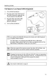
...) 1. Turn off the host device. 2. Plug the other end of the PC does not guarantee that scanned information will emit one beep. Plugging the scanner into the USB port of the USB interface cable into the 10-pin socket on the MS3780. 3. Plug the male 10-pin RJ45 end of... Keyboard Emulation Mode enabled. A software driver and correct configuration setting are also required for USB Serial Emulation Mode, please refer to occur. When the scanner first receives power the white LED will flash, one blue LED will turn on configuring the MS3780-38 for proper communication to the USB: Low...
...) 1. Turn off the host device. 2. Plug the other end of the PC does not guarantee that scanned information will emit one beep. Plugging the scanner into the USB port of the USB interface cable into the 10-pin socket on the MS3780. 3. Plug the male 10-pin RJ45 end of... Keyboard Emulation Mode enabled. A software driver and correct configuration setting are also required for USB Serial Emulation Mode, please refer to occur. When the scanner first receives power the white LED will flash, one blue LED will turn on configuring the MS3780-38 for proper communication to the USB: Low...

User Manual
Page 17
... returned to the stand it will automatically revert to the most recent scan pattern selected during in -stand pattern mode. When the scanner is out of its stand does not change the in -stand operation. 2. Please refer to the MetroSelect Configuration Guide for omnidirectional...below) activates the secondary scan pattern mode. By default, the secondary scan pattern is the default scan pattern active when the scanner starts. Figure 15. SCANNER OPERATION The Scan Pattern Mode Select Button There are two configurable scan pattern modes available with the MS3780. • The primary...
... returned to the stand it will automatically revert to the most recent scan pattern selected during in -stand pattern mode. When the scanner is out of its stand does not change the in -stand operation. 2. Please refer to the MetroSelect Configuration Guide for omnidirectional...below) activates the secondary scan pattern mode. By default, the secondary scan pattern is the default scan pattern active when the scanner starts. Figure 15. SCANNER OPERATION The Scan Pattern Mode Select Button There are two configurable scan pattern modes available with the MS3780. • The primary...
User Manual
Page 18
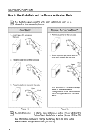
... (Amber LED is On) Out-of-Stand, CodeGate is active (Amber LED is not a default setting. Refer to the MetroSelect Configuration Guide (00-02407). 14 SCANNER OPERATION How to Use CodeGate and the Manual Activation Mode For illustration purposes the unit's scan pattern has been set to single-line (menu reading...
... (Amber LED is On) Out-of-Stand, CodeGate is active (Amber LED is not a default setting. Refer to the MetroSelect Configuration Guide (00-02407). 14 SCANNER OPERATION How to Use CodeGate and the Manual Activation Mode For illustration purposes the unit's scan pattern has been set to single-line (menu reading...
User Manual
Page 19
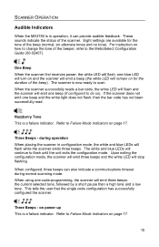
... Tone This is a failure indicator. Refer to flash until the unit exits the configuration mode. When using one blue LED will turn on and the scanner will emit a beep (the white LED will emit three beeps: the current selected tone, followed by a short pause then a high tone and a low tone. ...settings are available for the duration of the beeper, refer to scan. the white LED will flash, one -code-programming, the scanner will remain on for the tone of the scanner. Three Beeps - The white and blue LEDs will emit one beep and the white light does not flash, then the bar...
... Tone This is a failure indicator. Refer to flash until the unit exits the configuration mode. When using one blue LED will turn on and the scanner will emit a beep (the white LED will emit three beeps: the current selected tone, followed by a short pause then a high tone and a low tone. ...settings are available for the duration of the beeper, refer to scan. the white LED will flash, one -code-programming, the scanner will remain on for the tone of the scanner. Three Beeps - The white and blue LEDs will emit one beep and the white light does not flash, then the bar...

User Manual
Page 20
... LED will remain illuminated until the data can be received. The blue LED will not be illuminated if the scanner is deactivated. If the white LED does not flash or the scanner does not beep, then the bar code has not been successfully read. LED Indicators The LEDs will remain illuminated ... the host or transformer. They are also not illuminated when all lasers are four LEDs located on the top of the current scan and the scanner. The blue LED will remain on , the flashing or constant illumination of the LEDs indicates the status of the MS3780. If the host is deactivated...
... LED will remain illuminated until the data can be received. The blue LED will not be illuminated if the scanner is deactivated. If the white LED does not flash or the scanner does not beep, then the bar code has not been successfully read. LED Indicators The LEDs will remain illuminated ... the host or transformer. They are also not illuminated when all lasers are four LEDs located on the top of the current scan and the scanner. The blue LED will remain on , the flashing or constant illumination of the LEDs indicates the status of the MS3780. If the host is deactivated...
User Manual
Page 21
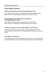
... Return the unit to a Metrologic authorized service center for repair. On Power Up This indicates that the nonvolatile memory that the scanner has experienced a laser subsystem failure. Return the unit to a Metrologic authorized service center for repair. 17 Both Blue LEDs and ... the unit to a Metrologic authorized service center for repair. Three Beeps - SCANNER OPERATION Failure Mode Indicators Both Blue LEDs Flashing with One Emitted Razzberry Tone This indicates that holds the scanner configuration has failed. Return the unit to a Metrologic authorized service center for ...
... Return the unit to a Metrologic authorized service center for repair. On Power Up This indicates that the nonvolatile memory that the scanner has experienced a laser subsystem failure. Return the unit to a Metrologic authorized service center for repair. 17 Both Blue LEDs and ... the unit to a Metrologic authorized service center for repair. Three Beeps - SCANNER OPERATION Failure Mode Indicators Both Blue LEDs Flashing with One Emitted Razzberry Tone This indicates that holds the scanner configuration has failed. Return the unit to a Metrologic authorized service center for ...
User Manual
Page 22
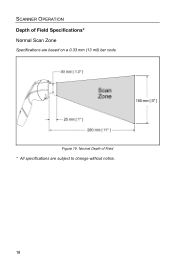
SCANNER OPERATION Depth of Field * All specifications are based on a 0.33 mm (13 mil) bar code. Figure 19. Normal Depth of Field Specifications* Normal Scan Zone Specifications are subject to change without notice. 18
SCANNER OPERATION Depth of Field * All specifications are based on a 0.33 mm (13 mil) bar code. Figure 19. Normal Depth of Field Specifications* Normal Scan Zone Specifications are subject to change without notice. 18

User Manual
Page 23
Figure 20. Reduced Depth of Field Specifications* Reduced Scan Zone Specifications are subject to change without notice. 19 SCANNER OPERATION Depth of Field * All specifications are based on a 0.33 mm (13 mil) bar code.
Figure 20. Reduced Depth of Field Specifications* Reduced Scan Zone Specifications are subject to change without notice. 19 SCANNER OPERATION Depth of Field * All specifications are based on a 0.33 mm (13 mil) bar code.


