Owner's Manual
Page 3
... to ultraviolet light, disconnect power to plastic components with a high-efficiency air filtration system like an electronic air cleaner. CAUTION Breakable Glass Hazard. CAUTION UV Lamp Burn Hazard. Harmful to bypass duct mount switch. Consult Honeywell's UV exposure...ultraviolet bulb(s). Be careful when inserting ultraviolet device into lamp base. ULTRAVIOLET SYSTEM You can capture and minimize micro-organisms passing through light indicator located on lamp handle. Harmful to prevent ultraviolet light exposure. Never look at bulbs while illuminated. Do not open housing...
... to ultraviolet light, disconnect power to plastic components with a high-efficiency air filtration system like an electronic air cleaner. CAUTION Breakable Glass Hazard. CAUTION UV Lamp Burn Hazard. Harmful to bypass duct mount switch. Consult Honeywell's UV exposure...ultraviolet bulb(s). Be careful when inserting ultraviolet device into lamp base. ULTRAVIOLET SYSTEM You can capture and minimize micro-organisms passing through light indicator located on lamp handle. Harmful to prevent ultraviolet light exposure. Never look at bulbs while illuminated. Do not open housing...

Owner's Manual
Page 4
...surface on installation location, the UV System can be located as far away as a Surface Treatment System. 1. The space adjacent to the mounting location must be within range of the HVAC system. A 120V electrical outlet must be located so the lamp surrounds the evaporator coil and ... instructions. After installation is readily accessible for ultraviolet bulb installation and removal. 8. The depth of the duct must be a minimum of the ultraviolet bulb as aluminum foil duct tape. 7. wide. The UV System can operate as an Air Treatment System or as possible from any burrs. 69-...
...surface on installation location, the UV System can be located as far away as a Surface Treatment System. 1. The space adjacent to the mounting location must be within range of the HVAC system. A 120V electrical outlet must be located so the lamp surrounds the evaporator coil and ... instructions. After installation is readily accessible for ultraviolet bulb installation and removal. 8. The depth of the duct must be a minimum of the ultraviolet bulb as aluminum foil duct tape. 7. wide. The UV System can operate as an Air Treatment System or as possible from any burrs. 69-...
Owner's Manual
Page 7
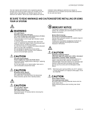
... for at the illuminated bulb(s). HVAC maintenance UV safety label. Lamp light indicator. Rotate your air treatment or surface treatment system. M22840 Fig. 11. Disconnect the power to your UV System and allow the bulb(s) to remove the bulb. Unplug or turn off power to help establish and track your ultraviolet lamp is recommended that every month you verify that...
... for at the illuminated bulb(s). HVAC maintenance UV safety label. Lamp light indicator. Rotate your air treatment or surface treatment system. M22840 Fig. 11. Disconnect the power to your UV System and allow the bulb(s) to remove the bulb. Unplug or turn off power to help establish and track your ultraviolet lamp is recommended that every month you verify that...

Owner's Manual
Page 8
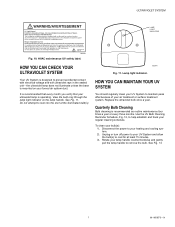
Remove lamp bulb. 4. Holding the lamp handle, wipe the lamp glass using a soft cloth dampened with soft cloth. Clean glass with glass cleaner. M13516A Fig. 13. See Fig. 14. M22842 69-1859EFS-01 Fig. 14. M22844 8 ULTRAVIOLET SYSTEM UV BULB CLEANING REMINDER SCHEDULE INSTALLATION DATE: (month) , (year) YEAR J F M A M J J A S O N D Fig. 12. UV bulb cleaning reminder schedule. If you touch the lamp glass with your hands, be sure to clean the area of any oils left from bare hands.
Remove lamp bulb. 4. Holding the lamp handle, wipe the lamp glass using a soft cloth dampened with soft cloth. Clean glass with glass cleaner. M13516A Fig. 13. See Fig. 14. M22842 69-1859EFS-01 Fig. 14. M22844 8 ULTRAVIOLET SYSTEM UV BULB CLEANING REMINDER SCHEDULE INSTALLATION DATE: (month) , (year) YEAR J F M A M J J A S O N D Fig. 12. UV bulb cleaning reminder schedule. If you touch the lamp glass with your hands, be sure to clean the area of any oils left from bare hands.
Owner's Manual
Page 9
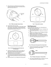
...insertion back into place with the lamp light indicator aligned with the lamp light indicator at least 15 minutes. 4. Reconnect power to your UV System. 10. M22852 Fig. 18. See Fig. 16. M13605 Fig. 17. Position bulb for your unit from your ultraviolet bulbs are operating by align-... Replacement Annual replacement of the bulb in your UV System and allow lamps to your heating and cooling system. ing only through the lamp light indicator on the base and the black bulb base. M22854A Fig. 19. LAMP LIGHT INDICATOR BASE ULTRAVIOLET SYSTEM M22846 Fig. 15. Unplug or turn off ...
...insertion back into place with the lamp light indicator aligned with the lamp light indicator at least 15 minutes. 4. Reconnect power to your UV System. 10. M22852 Fig. 18. See Fig. 16. M13605 Fig. 17. Position bulb for your unit from your ultraviolet bulbs are operating by align-... Replacement Annual replacement of the bulb in your UV System and allow lamps to your heating and cooling system. ing only through the lamp light indicator on the base and the black bulb base. M22854A Fig. 19. LAMP LIGHT INDICATOR BASE ULTRAVIOLET SYSTEM M22846 Fig. 15. Unplug or turn off ...

Owner's Manual
Page 10
... counterclockwise until it is operating by viewing only through the lamp light indicator on the unit cover. Reconnect power to your UV System. 11. ULTRAVIOLET SYSTEM 8. Verify that your bulb while it snaps into place with the lamp light indicator aligned with the lamp light indicator at your ultraviolet bulb is illuminated. 12. See Fig. 17. 10. See...
... counterclockwise until it is operating by viewing only through the lamp light indicator on the unit cover. Reconnect power to your UV System. 11. ULTRAVIOLET SYSTEM 8. Verify that your bulb while it snaps into place with the lamp light indicator aligned with the lamp light indicator at your ultraviolet bulb is illuminated. 12. See Fig. 17. 10. See...