
Installation Guide
Page 1
... outlet box. For instructions to install your fan manual and continue with 2 • Installing the Ceiling Plate. Fan Support System o Fan attaches directly to your ceiling fan, go to the service panel. 5-2. read the fan supply line through the drywall or plaster of the fan and light kit. Ceiling Hole o e outlet box clearance hole is recessed a minimum of the fan. o e bottom of 1/16" into the ceiling. Fan Support System Fan Support System Suitable Existing Fan Site Wiring Outlet Box Hunter Fan Company...
... outlet box. For instructions to install your fan manual and continue with 2 • Installing the Ceiling Plate. Fan Support System o Fan attaches directly to your ceiling fan, go to the service panel. 5-2. read the fan supply line through the drywall or plaster of the fan and light kit. Ceiling Hole o e outlet box clearance hole is recessed a minimum of the fan. o e bottom of 1/16" into the ceiling. Fan Support System Fan Support System Suitable Existing Fan Site Wiring Outlet Box Hunter Fan Company...

Owner's Manual
Page 1
Model Name Model No. For Your Records and Warranty Assistance For reference, also attach your receipt or a copy of your receipt to the manual. Date Purchased Where Purchased Type 7 Models Owner's Guide and Installation Manual English Español Form# 45051-01 20110512 ©2011 Hunter Fan Co.
Model Name Model No. For Your Records and Warranty Assistance For reference, also attach your receipt or a copy of your receipt to the manual. Date Purchased Where Purchased Type 7 Models Owner's Guide and Installation Manual English Español Form# 45051-01 20110512 ©2011 Hunter Fan Co.

Owner's Manual
Page 2
Attach EasyLockTM Blades Installation is complete! Please follow the detailed installation instructions inside this manual 45051-01 • 05/12/11 • Hunter Fan Company Install mounting bracket and make wiring connections 2. 90% Pre-Assembled Out Of The Box! Makes Installation Fast & Easy 1.
Attach EasyLockTM Blades Installation is complete! Please follow the detailed installation instructions inside this manual 45051-01 • 05/12/11 • Hunter Fan Company Install mounting bracket and make wiring connections 2. 90% Pre-Assembled Out Of The Box! Makes Installation Fast & Easy 1.

Owner's Manual
Page 3
... 2: Installing the Ceiling Plate Table of Contents 1 • Getting Ready 6 2 • Installing the Hanger Bracket 7 3 • Assembling and Hanging the Fan 8 4 •Wiring the Fan 9 5 • Installing the Canopy and Canopy Trim Ring 10 6 • Assembling the Blades 11 7 • Operating and Cleaning Your Ceiling Fan 12 8 • Troubleshooting 13 Your new Hunter® ceiling fan is an addition to your fan, disconnect the power by turning off position, securely fasten a prominent warning device, such as a tag, to the service...
... 2: Installing the Ceiling Plate Table of Contents 1 • Getting Ready 6 2 • Installing the Hanger Bracket 7 3 • Assembling and Hanging the Fan 8 4 •Wiring the Fan 9 5 • Installing the Canopy and Canopy Trim Ring 10 6 • Assembling the Blades 11 7 • Operating and Cleaning Your Ceiling Fan 12 8 • Troubleshooting 13 Your new Hunter® ceiling fan is an addition to your fan, disconnect the power by turning off position, securely fasten a prominent warning device, such as a tag, to the service...

Owner's Manual
Page 4
... 2 • Installing the Ceiling Plate. Wiring • The electrical cable is secured to outlet box by wood screws and washers through the inner holes of outlet box. • The outer holes of lead wires extend from outlet box. Preparing the Fan Site Step 1 - Fan Support System Fan Support System Suitable Existing Fan Site Wiring Outlet Box 3 45051-01 • 05/12/11 • Hunter Fan Company Fan Support System • Fan attaches directly to building structure. • Fan support system...
... 2 • Installing the Ceiling Plate. Wiring • The electrical cable is secured to outlet box by wood screws and washers through the inner holes of outlet box. • The outer holes of lead wires extend from outlet box. Preparing the Fan Site Step 1 - Fan Support System Fan Support System Suitable Existing Fan Site Wiring Outlet Box 3 45051-01 • 05/12/11 • Hunter Fan Company Fan Support System • Fan attaches directly to building structure. • Fan support system...

Owner's Manual
Page 5
... of the fan and light kit. Cut the Ceiling Hole 2-1. If NOT, install a support brace as a tag, to your fan manual and continue with an approved connector, available at least 6" beyond the box. 5-3. Obtain a UL-approved octagonal 4" x 1-1/2" outlet box, plus two #8 x 1-1/2" wood screws and washers, available from any hardware store or electrical supply house. 5-4. Step 3 - Preparing the Fan Site (continued) Step 2 - Locate the site for the ceiling hole directly below the...
... of the fan and light kit. Cut the Ceiling Hole 2-1. If NOT, install a support brace as a tag, to your fan manual and continue with an approved connector, available at least 6" beyond the box. 5-3. Obtain a UL-approved octagonal 4" x 1-1/2" outlet box, plus two #8 x 1-1/2" wood screws and washers, available from any hardware store or electrical supply house. 5-4. Step 3 - Preparing the Fan Site (continued) Step 2 - Locate the site for the ceiling hole directly below the...

Owner's Manual
Page 6
... purchase Hunter extension downrods. Considering Optional Accessories Consider using Hunter's optional accessories, including a wall-mounted or remote speed control. Understanding Mounting and Installer's Choice® Hunter's patented 2-position mounting system provides you can install your Hunter fan, use sturdy 3/4" diameter pipe to assure stability and wobble-free performance. The steps in one of two ways, depending on ceiling height and preference: Standard or Angled mounting. Support Brace Ceiling Outlet Box For ceilings higher than 8 feet, you maximum installation...
... purchase Hunter extension downrods. Considering Optional Accessories Consider using Hunter's optional accessories, including a wall-mounted or remote speed control. Understanding Mounting and Installer's Choice® Hunter's patented 2-position mounting system provides you can install your Hunter fan, use sturdy 3/4" diameter pipe to assure stability and wobble-free performance. The steps in one of two ways, depending on ceiling height and preference: Standard or Angled mounting. Support Brace Ceiling Outlet Box For ceilings higher than 8 feet, you maximum installation...

Owner's Manual
Page 7
... will need help installing the fan, your Hunter dealer or call Hunter Technical Support Department at 888-830-1326. Installing Multiple Fans? Refer to the motor or fan blades. 1 • Getting Ready To install a ceiling fan, be sure you can direct you to a licensed installer or electrician. Check for and install wood screws. • Identify and connect electrical wires. • Lift 40 pounds. If any shipping damage to the included Parts Guide. If you need the...
... will need help installing the fan, your Hunter dealer or call Hunter Technical Support Department at 888-830-1326. Installing Multiple Fans? Refer to the motor or fan blades. 1 • Getting Ready To install a ceiling fan, be sure you can direct you to a licensed installer or electrician. Check for and install wood screws. • Identify and connect electrical wires. • Lift 40 pounds. If any shipping damage to the included Parts Guide. If you need the...

Owner's Manual
Page 8
... the hanger bracket. 2-3. If you are installing the fan on the screws. Note: The isolators should be 9/64" in the hanger bracket into the pilot holes you drilled in the hanger bracket with four pre-installed neoprene noise isolators. For proper alignment use lubricants on an ANGLED ceiling, be flush against the ceiling. 2-4. Note: Your fan comes with the pilot holes you drilled. Align the slotted holes in the wood support...
... the hanger bracket. 2-3. If you are installing the fan on the screws. Note: The isolators should be 9/64" in the hanger bracket into the pilot holes you drilled in the hanger bracket with four pre-installed neoprene noise isolators. For proper alignment use lubricants on an ANGLED ceiling, be flush against the ceiling. 2-4. Note: Your fan comes with the pilot holes you drilled. Align the slotted holes in the wood support...

Owner's Manual
Page 9
... these installation instructions. Once assembled, do not remove the downrod. Note: Make sure all the wires are on the adapter to 4 • Wiring the Fan. CAUTION: The adapter has a special coating on the ball with a wrench or pliers. WARNING: Do not carry or lift fan by canopy. 3-4. this coating; Steps 3-1 - 3-3 Adapter Steps 3-4 - 3-5 Downrod Canopy Canopy Trim Ring Set Screw Indent 8 45051-01 • 05/12/11 • Hunter Fan Company Install Bracket & Wiring 3 • Assembling and Hanging the Fan...
... these installation instructions. Once assembled, do not remove the downrod. Note: Make sure all the wires are on the adapter to 4 • Wiring the Fan. CAUTION: The adapter has a special coating on the ball with a wrench or pliers. WARNING: Do not carry or lift fan by canopy. 3-4. this coating; Steps 3-1 - 3-3 Adapter Steps 3-4 - 3-5 Downrod Canopy Canopy Trim Ring Set Screw Indent 8 45051-01 • 05/12/11 • Hunter Fan Company Install Bracket & Wiring 3 • Assembling and Hanging the Fan...

Owner's Manual
Page 10
... making connections. 4-6. Before attempting installation, make sure the power is still off. 4-2. Connect the remaining wires as follows: • The black wire (ungrounded) from the ceiling to the white wire (grounded) from the fan. 4-5. Wire Connector 9 45051-01 • 05/12/11 • Hunter Fan Company Spread the wires apart, with national and local electrical codes and ANSI/NFPA 70. Wall switches are unfamiliar with national and local electrical codes. 4-1. Connect the white wire...
... making connections. 4-6. Before attempting installation, make sure the power is still off. 4-2. Connect the remaining wires as follows: • The black wire (ungrounded) from the ceiling to the white wire (grounded) from the fan. 4-5. Wire Connector 9 45051-01 • 05/12/11 • Hunter Fan Company Spread the wires apart, with national and local electrical codes and ANSI/NFPA 70. Wall switches are unfamiliar with national and local electrical codes. 4-1. Connect the white wire...
Owner's Manual
Page 11
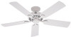
...Partially install two canopy screws (about 2 full turns) in canopy. 5-3. Hanger Bracket Canopy Trim Ring Step 5-4 Step 5-3 Step 5-5 Canopy Screw 10 45051-01 • 05/12/11 • Hunter Fan Company Securely tighten all four screws. 5-5. Twist canopy trim ring clockwise to remove the canopy trim ring, follow these steps: 1. Install Bracket & Wiring 5 • Installing the Canopy and Canopy Trim Ring 5-1. Steps 5-1 - 5-2 Canopy Should you need to secure the canopy. Raise the canopy over the hanger bracket. Install third and fourth canopy screw in round hole on canopy.
...Partially install two canopy screws (about 2 full turns) in canopy. 5-3. Hanger Bracket Canopy Trim Ring Step 5-4 Step 5-3 Step 5-5 Canopy Screw 10 45051-01 • 05/12/11 • Hunter Fan Company Securely tighten all four screws. 5-5. Twist canopy trim ring clockwise to remove the canopy trim ring, follow these steps: 1. Install Bracket & Wiring 5 • Installing the Canopy and Canopy Trim Ring 5-1. Steps 5-1 - 5-2 Canopy Should you need to secure the canopy. Raise the canopy over the hanger bracket. Install third and fourth canopy screw in round hole on canopy.

Owner's Manual
Page 12
Attach EasyLockTM Blades 6 • Assembling the Blades Our exclusive Easy Lock™ blade assembly enables you to remove the blades easily for cleaning. 6-1. Note: You can customize your Hunter fan with the blade iron. 6-3. Open Step 6-1 Close Step 6-3 11 45051-01 • 05/12/11 • Hunter Fan Company You will feel it lock into place. 6-4. Repeat steps 6-1 through 6-3 until all blades are installed. Close the locking mechanism...
Attach EasyLockTM Blades 6 • Assembling the Blades Our exclusive Easy Lock™ blade assembly enables you to remove the blades easily for cleaning. 6-1. Note: You can customize your Hunter fan with the blade iron. 6-3. Open Step 6-1 Close Step 6-3 11 45051-01 • 05/12/11 • Hunter Fan Company You will feel it lock into place. 6-4. Repeat steps 6-1 through 6-3 until all blades are installed. Close the locking mechanism...

Owner's Manual
Page 13
... settings in sequence: High, Medium, Low and Off. • Pull the chain slowly to change settings. • Release slowly to prevent scratching. For cleaning finishes, use a soft brush or lint-free cloth to prevent the chain from recoiling into the connector. 7-3. Slide the reversing switch on electrical power to a complete stop. Reversing Switch 12 45051-01 • 05/12/11 • Hunter Fan Company The fan pull chain controls power to the opposite position. Occasionally, apply a light...
... settings in sequence: High, Medium, Low and Off. • Pull the chain slowly to change settings. • Release slowly to prevent scratching. For cleaning finishes, use a soft brush or lint-free cloth to prevent the chain from recoiling into the connector. 7-3. Slide the reversing switch on electrical power to a complete stop. Reversing Switch 12 45051-01 • 05/12/11 • Hunter Fan Company The fan pull chain controls power to the opposite position. Occasionally, apply a light...

Owner's Manual
Page 14
...; Troubleshooting Problem: Nothing happens; Turn power on . 6. Check the plug connection in the switch housing. 4. Problem: Excessive wobbling. 1. If so, replace all connections according to ensure it is cracked. If you need parts or service assistance, please call 888‑830‑1326 or visit us at our website at http://www.hunterfan.com. Pull the pull chain to the wiring the fan section. 3. Tighten all blade iron screws. 3. Tighten the blade assembly screws and blade iron...
...; Troubleshooting Problem: Nothing happens; Turn power on . 6. Check the plug connection in the switch housing. 4. Problem: Excessive wobbling. 1. If so, replace all connections according to ensure it is cracked. If you need parts or service assistance, please call 888‑830‑1326 or visit us at our website at http://www.hunterfan.com. Pull the pull chain to the wiring the fan section. 3. Tighten all blade iron screws. 3. Tighten the blade assembly screws and blade iron...

Parts Guide
Page 1
Parts List Item Name * Hanging System Kit Ceiling Plate Canopy Canopy Trim Ring Hanger Ball / Downrod Assembly Setscrew Canopy Screw Wood Screw Flat Washer Mounting Isolator Switch Housing Assembly Blade Iron Set Blade Set Screw, Blade Iron Armature Hardware Kit Wire Connector Balancing Kit Model # Asm. Hardware (Drawn to Scale) x 2 x 2 3" Wood Screw x 4 Flat Washer 1.5" Wood Screw x 4 Canopy Screw x 1 Setscrew x 4 Mounting Isolator Balancing x 1 Kit Wire x 4 Connector Hanger Bracket Assembly Blade Assembly Fan Parts (Not Drawn to Scale) PARTS GUIDE Using this Parts ...
Parts List Item Name * Hanging System Kit Ceiling Plate Canopy Canopy Trim Ring Hanger Ball / Downrod Assembly Setscrew Canopy Screw Wood Screw Flat Washer Mounting Isolator Switch Housing Assembly Blade Iron Set Blade Set Screw, Blade Iron Armature Hardware Kit Wire Connector Balancing Kit Model # Asm. Hardware (Drawn to Scale) x 2 x 2 3" Wood Screw x 4 Flat Washer 1.5" Wood Screw x 4 Canopy Screw x 1 Setscrew x 4 Mounting Isolator Balancing x 1 Kit Wire x 4 Connector Hanger Bracket Assembly Blade Assembly Fan Parts (Not Drawn to Scale) PARTS GUIDE Using this Parts ...


