
Installation Guide
Page 1
... associated wall switch location are essential for the ceiling hole directly below the joist or support brace. For instructions to install your ceiling fan, go to your fan manual and begin with an approved connector, available at least 8 feet high. • e fan blades have now successfully prepared your ceiling fan site. o Fan support system will support the full weight of 1/16" into the ceiling. 3-2. Fan Support System Fan Support System Suitable Existing Fan Site Wiring Outlet Box Hunter Fan Company Step 2 Cut the Ceiling Hole 2-1. Locate...
... associated wall switch location are essential for the ceiling hole directly below the joist or support brace. For instructions to install your ceiling fan, go to your fan manual and begin with an approved connector, available at least 8 feet high. • e fan blades have now successfully prepared your ceiling fan site. o Fan support system will support the full weight of 1/16" into the ceiling. 3-2. Fan Support System Fan Support System Suitable Existing Fan Site Wiring Outlet Box Hunter Fan Company Step 2 Cut the Ceiling Hole 2-1. Locate...

Owner's Manual
Page 1
For Your Records and Warranty Assistance Model Name Catalog/Model No Serial No Date Purchased Where Purchased For reference also attach your receipt or a copy of your receipt to the manual. 42800-01 • 01/18/06
For Your Records and Warranty Assistance Model Name Catalog/Model No Serial No Date Purchased Where Purchased For reference also attach your receipt or a copy of your receipt to the manual. 42800-01 • 01/18/06
Owner's Manual
Page 2
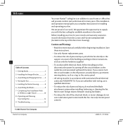
... instructions, and use a solid-state speed control with national and local electrical codes and ANSI/NFPA 70. If you are proud of our work. Welcome 2 Table of Contents 1 • Getting Ready 4 2 • Installing the Hanger Bracket 5 3 • Assembling and Hanging the Fan..........6 4 • Wiring the Fan 7 5 • Installing the Motor Housing 8 6 • Assembling the Blades 9 7 • Completing Your Installation With or Without a Light Fixture 10 8 • Operating and Cleaning Your Ceiling Fan 14 9 • Troubleshooting 15 Your new Hunter® ceiling fan...
... instructions, and use a solid-state speed control with national and local electrical codes and ANSI/NFPA 70. If you are proud of our work. Welcome 2 Table of Contents 1 • Getting Ready 4 2 • Installing the Hanger Bracket 5 3 • Assembling and Hanging the Fan..........6 4 • Wiring the Fan 7 5 • Installing the Motor Housing 8 6 • Assembling the Blades 9 7 • Completing Your Installation With or Without a Light Fixture 10 8 • Operating and Cleaning Your Ceiling Fan 14 9 • Troubleshooting 15 Your new Hunter® ceiling fan...

Owner's Manual
Page 3
... only on flat ceilings and can be used on ceilings less than 8 feet high 3 42800-01 • 01/18/06 Hunter Fan Company g, recommended for ceilings less than 8 feet high. LoLwoPwroPfriolefilMe oMuonutinntginfgitsfictslocsleosteottohethe ceiclienilgin. Considering Optional Accessories Consider using Hunter's optional accessories, including a wall-mounted or remote speed control. Mounting and Optional Accessories Understanding Mounting Hunter's patented mounting system provides you maximum ease in installing your Hunter fan, use the accessories, follow the instructions included with...
... only on flat ceilings and can be used on ceilings less than 8 feet high 3 42800-01 • 01/18/06 Hunter Fan Company g, recommended for ceilings less than 8 feet high. LoLwoPwroPfriolefilMe oMuonutinntginfgitsfictslocsleosteottohethe ceiclienilgin. Considering Optional Accessories Consider using Hunter's optional accessories, including a wall-mounted or remote speed control. Mounting and Optional Accessories Understanding Mounting Hunter's patented mounting system provides you maximum ease in installing your Hunter fan, use the accessories, follow the instructions included with...

Owner's Manual
Page 4
... for and install wood screws. • Identify and connect electrical wires. • Lift 40 pounds. Proper ceiling fan location and attachment to the building structure are essential for any parts are installing more than one fan, keep the fan blades and blade irons (if applicable) in sets, as they were shipped. If you to the included Parts Guide. Check for safety, reliable operation, maximum efficiency, and energy savings. Hunter Fan Company 42800-01...
... for and install wood screws. • Identify and connect electrical wires. • Lift 40 pounds. Proper ceiling fan location and attachment to the building structure are essential for any parts are installing more than one fan, keep the fan blades and blade irons (if applicable) in sets, as they were shipped. If you to the included Parts Guide. Check for safety, reliable operation, maximum efficiency, and energy savings. Hunter Fan Company 42800-01...
Owner's Manual
Page 5
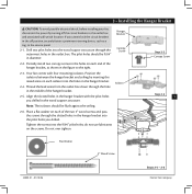
... slotted holes in the hanger bracket with four mounting isolators. Place a flat washer on each end of the hanger bracket, as a tag, to the service panel. 2-1. do not use lubricants on each of the hanger bracket. Partially install two canopy screws in the holes on each isolator into the holes in the hanger bracket. 2-4. read the lead wires from the outlet box down through the outermost holes in the outlet box. e pilot holes...
... slotted holes in the hanger bracket with four mounting isolators. Place a flat washer on each end of the hanger bracket, as a tag, to the service panel. 2-1. do not use lubricants on each of the hanger bracket. Partially install two canopy screws in the holes on each isolator into the holes in the hanger bracket. 2-4. read the lead wires from the outlet box down through the outermost holes in the outlet box. e pilot holes...

Owner's Manual
Page 6
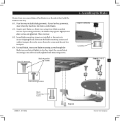
... result in the fan falling. 3-3. WARNING: Make sure the square hanger can not rotate in the side of the large opening in the metal bracket. 3-2. Install two locking screws through the holes in the metal bracket. 3 • Assembling and Hanging the Fan Step 3-1 Square Hanger 3-1. Failure to secure the square hanger. Motor Assembly Step 3-2 Green Ground Wire 6 Green Ground Wire Step 3-3 #8-32 x 1" Screw Locking Screw Hunter Fan Company 42800-01 •...
... result in the fan falling. 3-3. WARNING: Make sure the square hanger can not rotate in the side of the large opening in the metal bracket. 3-2. Install two locking screws through the holes in the metal bracket. 3 • Assembling and Hanging the Fan Step 3-1 Square Hanger 3-1. Failure to secure the square hanger. Motor Assembly Step 3-2 Green Ground Wire 6 Green Ground Wire Step 3-3 #8-32 x 1" Screw Locking Screw Hunter Fan Company 42800-01 •...
Owner's Manual
Page 7
... the black wire from the fan 4-4. Push all wires and wire nuts back through the ceiling plate hole into the outlet box. 4 •Wiring the Fan Step 4-3 7 Wire Nut 42800-01 • 01/18/06 Hunter Fan Company CAUTION: Be sure no bare wire or wire strands are unfamiliar with national and local electrical codes and ANSI/NFPA 70. All wiring must be in accordance with wiring, use a qualified electrician. 4-1. Connect the wires as...
... the black wire from the fan 4-4. Push all wires and wire nuts back through the ceiling plate hole into the outlet box. 4 •Wiring the Fan Step 4-3 7 Wire Nut 42800-01 • 01/18/06 Hunter Fan Company CAUTION: Be sure no bare wire or wire strands are unfamiliar with national and local electrical codes and ANSI/NFPA 70. All wiring must be in accordance with wiring, use a qualified electrician. 4-1. Connect the wires as...
Owner's Manual
Page 8
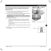
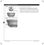
Align the keyholes in the fan housing with the two partially installed canopy screws in the fan housing and into the holes in the hanger bracket. Securely tighten all screws. Step 5-3 8 Canopy Screw Hunter Fan Company 42800-01 • 01/18/06 5 • Installing the Motor Housing Step 5-1 Motor Fan Housing 5-1. Install the two remaining canopy screws into the hanger bracket. Rotate the fan housing to situate the screws in the narrow ends of the keyholes. 5-3. Place the fan housing over the motor. 5-2.
Align the keyholes in the fan housing with the two partially installed canopy screws in the fan housing and into the holes in the hanger bracket. Securely tighten all screws. Step 5-3 8 Canopy Screw Hunter Fan Company 42800-01 • 01/18/06 5 • Installing the Motor Housing Step 5-1 Motor Fan Housing 5-1. Install the two remaining canopy screws into the hanger bracket. Rotate the fan housing to situate the screws in the narrow ends of the keyholes. 5-3. Place the fan housing over the motor. 5-2.
Owner's Manual
Page 9
... holes on the blades. 6-2. Remove the blade mounting screws and rubber bumpers from the motor. If you used grommets, the blades may include blade grommets. Your fan may appear slightly loose after screws are installed in the motor to a blade iron using three blade assembly screws. Save the screws and discard the bumpers. 6-4. Insert the second blade mounting screw, then securely tighten both mounting screws. Attach each blade, insert one blade mounting screw through the blade iron, and attach lightly to the fan). 6-1. Hunter fans use several styles of fan blade irons (brackets...
... holes on the blades. 6-2. Remove the blade mounting screws and rubber bumpers from the motor. If you used grommets, the blades may include blade grommets. Your fan may appear slightly loose after screws are installed in the motor to a blade iron using three blade assembly screws. Save the screws and discard the bumpers. 6-4. Insert the second blade mounting screw, then securely tighten both mounting screws. Attach each blade, insert one blade mounting screw through the blade iron, and attach lightly to the fan). 6-1. Hunter fans use several styles of fan blade irons (brackets...
Owner's Manual
Page 10
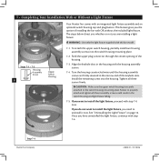
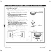
... housing assembly screws are installing a light fixture. 7 • Completing Your Installation With or Without a Light Fixture Steps 7-1 - 7-3 Housing Assembly Screw 10 Upper Switch Housing Your Hunter fan comes with an integrated light fixture assembly and an optional switch housing cap and plug button. is securely attached to properly attach and tighten all three screws firmly. Feed the upper plug connector through the center opening of the keyhole slots. Install the remaining screw into the switch housing mounting plate. 7-2. Tighten all three assembly screws...
... housing assembly screws are installing a light fixture. 7 • Completing Your Installation With or Without a Light Fixture Steps 7-1 - 7-3 Housing Assembly Screw 10 Upper Switch Housing Your Hunter fan comes with an integrated light fixture assembly and an optional switch housing cap and plug button. is securely attached to properly attach and tighten all three screws firmly. Feed the upper plug connector through the center opening of the keyhole slots. Install the remaining screw into the switch housing mounting plate. 7-2. Tighten all three assembly screws...
Owner's Manual
Page 11
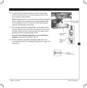
... connector from the motor to install the glass bowl. Otherwise, proceed with three housing assembly screws. Incorrect connection could cause improper operation and damage to the upper switch housing with step 7-8. 7-8. e last installation step when installing the light fixture is complete. Place the lower switch housing assembly over the upper switch housing. Attach the lower switch housing to the product. 7-7. 7-6. Steps 7-6 - 7-7 Lower Switch Housing Plug Connector Detail Plug Connector 11 Housing Assembly Screw 42800-01 • 01/18/06 Hunter Fan Company...
... connector from the motor to install the glass bowl. Otherwise, proceed with three housing assembly screws. Incorrect connection could cause improper operation and damage to the upper switch housing with step 7-8. 7-8. e last installation step when installing the light fixture is complete. Place the lower switch housing assembly over the upper switch housing. Attach the lower switch housing to the product. 7-7. 7-6. Steps 7-6 - 7-7 Lower Switch Housing Plug Connector Detail Plug Connector 11 Housing Assembly Screw 42800-01 • 01/18/06 Hunter Fan Company...
Owner's Manual
Page 12
... the lower switch housing pulling disconnected wires through the hole. 12 6. Disconnect the plug connectors between the black wire and the black/white wire. 2. Unscrew the threaded rod of the light fixture from the end of the lower switch housing. Install the switch housing cap and plug button to the lower switch housing. To uninstall the light fixture, first disconnect the plug connectors between the two white wires. 3. Male Dummy Terminal Female Dummy Terminal Cap Lower Switch Housing readed Rod Steps 3 - 5 Plug Button Step 7 Hunter Fan Company...
... the lower switch housing pulling disconnected wires through the hole. 12 6. Disconnect the plug connectors between the black wire and the black/white wire. 2. Unscrew the threaded rod of the light fixture from the end of the lower switch housing. Install the switch housing cap and plug button to the lower switch housing. To uninstall the light fixture, first disconnect the plug connectors between the two white wires. 3. Male Dummy Terminal Female Dummy Terminal Cap Lower Switch Housing readed Rod Steps 3 - 5 Plug Button Step 7 Hunter Fan Company...
Owner's Manual
Page 13
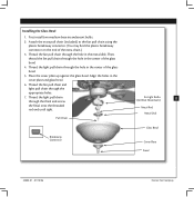
... of the glass bowl. 4. read the light pull chain through the hole in the cover plate and glass bowl. 6. read the fan pull chain and light pull chain through the appropriate holes. 7. read the light pull chain through the finial and screw the finial onto the threaded rod end until tight. Pull Chain Breakaway Connector for Light Bulbs (60 Watt Maximum) 13 Metal Rod Metal Disk Glass Bowl Cover Plate Finial 42800-01 • 01/18/06 Hunter Fan Company Align the holes in...
... of the glass bowl. 4. read the light pull chain through the hole in the cover plate and glass bowl. 6. read the fan pull chain and light pull chain through the appropriate holes. 7. read the light pull chain through the finial and screw the finial onto the threaded rod end until tight. Pull Chain Breakaway Connector for Light Bulbs (60 Watt Maximum) 13 Metal Rod Metal Disk Glass Bowl Cover Plate Finial 42800-01 • 01/18/06 Hunter Fan Company Align the holes in...

Owner's Manual
Page 14
... reversing switch on electrical power to the fan. 8-2. e fan pull chain controls power to the fan. e pull chain has four settings in warm weather to prevent scratching. In warm weather, use upward air flow pattern 8-6. Reversing Switch Hunter Fan Company 42800-01 • 01/18/06 To Change Airflow Direction Turn the fan off and let it come to the light. e pull chain has two settings: On and Off. 8-4. 8 • Operating and Cleaning Your Ceiling Fan 8-1. In cold weather, use...
... reversing switch on electrical power to the fan. 8-2. e fan pull chain controls power to the fan. e pull chain has four settings in warm weather to prevent scratching. In warm weather, use upward air flow pattern 8-6. Reversing Switch Hunter Fan Company 42800-01 • 01/18/06 To Change Airflow Direction Turn the fan off and let it come to the light. e pull chain has two settings: On and Off. 8-4. 8 • Operating and Cleaning Your Ceiling Fan 8-1. In cold weather, use...

Owner's Manual
Page 15
... glass is cracked. If so, replace all blade and/or blade iron screws. Check and tighten the screws in the switch housing mounting plate and in the switch housing. 4. Hunter Fan Company 2500 Frisco Avenue Memphis, Tennessee 38114 42800-01 • 01/18/06 9 • Troubleshooting 15 Hunter Fan Company Loosen canopy, check all connections according to balance the fan. 2. Remove the shipping bumpers. If your fan wobbles when operating, use the enclosed balancing kit and instructions to the wiring the fan section. 3. Change...
... glass is cracked. If so, replace all blade and/or blade iron screws. Check and tighten the screws in the switch housing mounting plate and in the switch housing. 4. Hunter Fan Company 2500 Frisco Avenue Memphis, Tennessee 38114 42800-01 • 01/18/06 9 • Troubleshooting 15 Hunter Fan Company Loosen canopy, check all connections according to balance the fan. 2. Remove the shipping bumpers. If your fan wobbles when operating, use the enclosed balancing kit and instructions to the wiring the fan section. 3. Change...
Parts Guide
Page 1
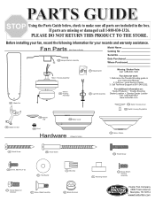
...on: Hunter Products Trouble Shooting Dealer Location Service Center Locator Call 1-800-448-6837 www.hunterfan.com 152 Switch Housing Cover 153 Switch Housing Plug Button 148 Bottom Cap 226 Motor Cover 44 Blade Iron Set 149 Finial Hardware (Drawn to Scale) 239 Hanger Bracket Assembly Model Name Catalog No. Fan Parts (Not Drawn to Scale) 150 Globe / Shade 64 Wood Screw 65 Wood Screw 156 Thumb Screw 69 Screw, Machine, 6-32 68 Flat Washer 70 Wire Nut 47 Screw, Blade Iron Armature 67 Screw, Blade Assembly 66 Blade Grommet 71 Mounting Isolator 131 Screw, Switch Housing Assembly...
...on: Hunter Products Trouble Shooting Dealer Location Service Center Locator Call 1-800-448-6837 www.hunterfan.com 152 Switch Housing Cover 153 Switch Housing Plug Button 148 Bottom Cap 226 Motor Cover 44 Blade Iron Set 149 Finial Hardware (Drawn to Scale) 239 Hanger Bracket Assembly Model Name Catalog No. Fan Parts (Not Drawn to Scale) 150 Globe / Shade 64 Wood Screw 65 Wood Screw 156 Thumb Screw 69 Screw, Machine, 6-32 68 Flat Washer 70 Wire Nut 47 Screw, Blade Iron Armature 67 Screw, Blade Assembly 66 Blade Grommet 71 Mounting Isolator 131 Screw, Switch Housing Assembly...
Parts Guide
Page 2
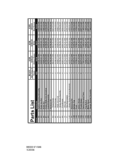
... 70 71 131 75 148 149 150 156 152 153 226 239 Item Name Switch / Housing Assembly Blade Iron Set Blade Set Screw, Blade Iron Armature Light Kit Assembly * Hardware Kit Wood Screw Wood Screw Blade Grommet Screw, Blade Assembly Flat Washer Wire Nut Mounting Isolator Screw, Switch Housing Assembly Balancing Kit Bottom Cap Finial Globe / Shade Thumb Screw Switch Housing Cover Plug Button Motor Cover Hanger Bracket Assembly Model # Asm. Dwg. # Finish Qnty 1 1 1 8 1 1 2 2 12 12 4 4 4 3 1 1 1 1 9 1 1 1 1 22363 96702-01 Antique Brass Part # 93529-05-000 92803-06-121 75885-03-000 63755-05-232 84678...
... 70 71 131 75 148 149 150 156 152 153 226 239 Item Name Switch / Housing Assembly Blade Iron Set Blade Set Screw, Blade Iron Armature Light Kit Assembly * Hardware Kit Wood Screw Wood Screw Blade Grommet Screw, Blade Assembly Flat Washer Wire Nut Mounting Isolator Screw, Switch Housing Assembly Balancing Kit Bottom Cap Finial Globe / Shade Thumb Screw Switch Housing Cover Plug Button Motor Cover Hanger Bracket Assembly Model # Asm. Dwg. # Finish Qnty 1 1 1 8 1 1 2 2 12 12 4 4 4 3 1 1 1 1 9 1 1 1 1 22363 96702-01 Antique Brass Part # 93529-05-000 92803-06-121 75885-03-000 63755-05-232 84678...


