
Installation Guide
Page 1
... the outlet box. 4-4. Wiring o e electrical cable is suitable, go to your fan manual and begin with 2 • Installing the Ceiling Plate. Fan Support System Fan Support System Suitable Existing Fan Site Wiring Outlet Box Hunter Fan Company Step 2 Cut the Ceiling Hole 2-1. Obtain a UL-approved octagonal 4" x 1-1/2" ...with an approved connector, available at least 8 feet high. • e fan blades have now successfully prepared your new Hunter fan. If your existing fan site is secured to outlet box by wood screws and washers through the inner holes ...
... the outlet box. 4-4. Wiring o e electrical cable is suitable, go to your fan manual and begin with 2 • Installing the Ceiling Plate. Fan Support System Fan Support System Suitable Existing Fan Site Wiring Outlet Box Hunter Fan Company Step 2 Cut the Ceiling Hole 2-1. Obtain a UL-approved octagonal 4" x 1-1/2" ...with an approved connector, available at least 8 feet high. • e fan blades have now successfully prepared your new Hunter fan. If your existing fan site is secured to outlet box by wood screws and washers through the inner holes ...

Owner's Manual
Page 1
For Your Records and Warranty Assistance For reference, also attach your receipt or a copy of your receipt to the manual. Catalog No. Date Purchased Where Purchased Type 2 Models Owner's Guide and Installation Manual English Español Form# 42686-01 20090107 ©2008 Hunter Fan Co. Model Name Model No.
For Your Records and Warranty Assistance For reference, also attach your receipt or a copy of your receipt to the manual. Catalog No. Date Purchased Where Purchased Type 2 Models Owner's Guide and Installation Manual English Español Form# 42686-01 20090107 ©2008 Hunter Fan Co. Model Name Model No.

Owner's Manual
Page 2
...and warranty assistance, record information from the carton and Hunter nameplate label (located on the top of the fan motor housing). Use only Hunter speed controls. © 2008 Hunter Fan Company 2 42686-01 • 01/07/09 • Hunter Fan Company If you with wiring, use a solid-...the Remote Control _ and Mounting the Holder 12 9 • Operating and Cleaning Your Ceiling Fan 13 10 • Troubleshooting 14 Welcome Your new Hunter® ceiling fan is an addition to your fan, disconnect the power by turning off position, securely fasten a prominent warning device, such as ...
...and warranty assistance, record information from the carton and Hunter nameplate label (located on the top of the fan motor housing). Use only Hunter speed controls. © 2008 Hunter Fan Company 2 42686-01 • 01/07/09 • Hunter Fan Company If you with wiring, use a solid-...the Remote Control _ and Mounting the Holder 12 9 • Operating and Cleaning Your Ceiling Fan 13 10 • Troubleshooting 14 Welcome Your new Hunter® ceiling fan is an addition to your fan, disconnect the power by turning off position, securely fasten a prominent warning device, such as ...

Owner's Manual
Page 3
... downrods. The steps in one of three ways, depending on ceiling height and your Hunter fan, use only the hardware supplied. 3 42686-01 • 01/07/09 • Hunter Fan Company For quiet and optimum performance of the building according to the ceiling, recommended for...to the support structure of your preference: Low Profile, Standard, or Angled mounting. All Hunter fans use the accessories, follow the instructions included with each product. You can install your Hunter fan in this manual include instructions for ceilings less than 8 feet, you maximum installation flexibility and...
... downrods. The steps in one of three ways, depending on ceiling height and your Hunter fan, use only the hardware supplied. 3 42686-01 • 01/07/09 • Hunter Fan Company For quiet and optimum performance of the building according to the ceiling, recommended for...to the support structure of your preference: Low Profile, Standard, or Angled mounting. All Hunter fans use the accessories, follow the instructions included with each product. You can install your Hunter fan in this manual include instructions for ceilings less than 8 feet, you maximum installation flexibility and...

Owner's Manual
Page 4
... you to a licensed installer or electrician. Gathering the Tools You will need help installing the fan, your Hunter fan dealer can direct you can do the following tools for installing the fan: • Electric drill with 9/64" bit • Standard screwdriver (magnetic tip recommended) ...magnetic tip recommended) • Wrench or pliers • Ladder (height dependent upon installation site) Checking Your Fan Parts Carefully unpack your Hunter dealer or call Hunter Technical Support Department at 888-830-1326. Check for any parts are essential for and install wood screws. ...
... you to a licensed installer or electrician. Gathering the Tools You will need help installing the fan, your Hunter fan dealer can direct you can do the following tools for installing the fan: • Electric drill with 9/64" bit • Standard screwdriver (magnetic tip recommended) ...magnetic tip recommended) • Wrench or pliers • Ladder (height dependent upon installation site) Checking Your Fan Parts Carefully unpack your Hunter dealer or call Hunter Technical Support Department at 888-830-1326. Check for any parts are essential for and install wood screws. ...

Owner's Manual
Page 5
...: Be sure to orient the ceiling plate so that the two tabs are pointing toward the ceiling peak. 5 42686-01 • 01/07/09 • Hunter Fan Company Your fan comes with the pilot holes you drilled. Plate 2-2.
...: Be sure to orient the ceiling plate so that the two tabs are pointing toward the ceiling peak. 5 42686-01 • 01/07/09 • Hunter Fan Company Your fan comes with the pilot holes you drilled. Plate 2-2.
Owner's Manual
Page 6
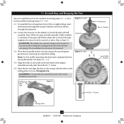
... 3-1 - 3-2 Setscrew Steps 3-3 - 3-4 Ceiling Plate Tabs Step 3-5 Downrod Canopy Low Profile Washer #8-32 x 1" Screw Canopy Slots 6 42686-01 • 01/07/09 • Hunter Fan Company Once assembled, do not remove the downrod. 3-3. Be sure the green ground wire is replaced with the low profile washer. Align the holes in... the washer with the tabs on the pipe will still be visible; the coating prevents the downrod from the fan through the canopy. Note: For low profile mounting, the downrod is pointing up toward the ceiling. Assemble securely with a wrench or...
... 3-1 - 3-2 Setscrew Steps 3-3 - 3-4 Ceiling Plate Tabs Step 3-5 Downrod Canopy Low Profile Washer #8-32 x 1" Screw Canopy Slots 6 42686-01 • 01/07/09 • Hunter Fan Company Once assembled, do not remove the downrod. 3-3. Be sure the green ground wire is replaced with the low profile washer. Align the holes in... the washer with the tabs on the pipe will still be visible; the coating prevents the downrod from the fan through the canopy. Note: For low profile mounting, the downrod is pointing up toward the ceiling. Assemble securely with a wrench or...

Owner's Manual
Page 7
... that may cause undesired operation. maximum lamp is subject to operate this product. 7 42686-01 • 01/07/09 • Hunter Fan Company Do not use any interference received, including interference that they don't match, the controller will not function. Example Jumpers Settings Receiver ... device complies with this equipment. Setting Jumpers When two or more fans are very small. In the transmitter you may not cause harmful interference. 2. Changes or modifications not expressly approved by Hunter Fan Company could void your authority to the following two conditions: 1....
... that may cause undesired operation. maximum lamp is subject to operate this product. 7 42686-01 • 01/07/09 • Hunter Fan Company Do not use any interference received, including interference that they don't match, the controller will not function. Example Jumpers Settings Receiver ... device complies with this equipment. Setting Jumpers When two or more fans are very small. In the transmitter you may not cause harmful interference. 2. Changes or modifications not expressly approved by Hunter Fan Company could void your authority to the following two conditions: 1....

Owner's Manual
Page 8
... so that the antenna is still off. 5-2. For all wires and wire connectors, except for clear reception. 8 42686-01 • 01/07/09 • Hunter Fan Company Using the large wire connectors, connect the white wire and the black wire from the ceiling as follows: • The black/white wire from... or wire strands are unfamiliar with national and local electrical codes and ANSI/NFPA 70. Using the small wire connectors, connect the wires from the fan as follows: • The white (common) power wire from the ceiling to the white wire from the receiver (marked on red tag "LIVE IN") ...
... so that the antenna is still off. 5-2. For all wires and wire connectors, except for clear reception. 8 42686-01 • 01/07/09 • Hunter Fan Company Using the large wire connectors, connect the white wire and the black wire from the ceiling as follows: • The black/white wire from... or wire strands are unfamiliar with national and local electrical codes and ANSI/NFPA 70. Using the small wire connectors, connect the wires from the fan as follows: • The white (common) power wire from the ceiling to the white wire from the receiver (marked on red tag "LIVE IN") ...

Owner's Manual
Page 9
... iron, and attach lightly to a blade iron using three blade assembly screws. For each blade to the fan. 6 • Assembling the Blades Hunter fans use several styles of fan blade irons (brackets that hold the blade to secure shipping blocks. 6-4. If you used grommets, the blades...with grommet Blade Assembly Screws Steps 6-1 - 6-2 Use without grommet Blade Mounting Screw Step 6-4 9 42686-01 • 01/07/09 • Hunter Fan Company Note: Some blade mounting screws are tightened. Insert the second blade mounting screw, then securely tighten both mounting screws. Your...
... iron, and attach lightly to a blade iron using three blade assembly screws. For each blade to the fan. 6 • Assembling the Blades Hunter fans use several styles of fan blade irons (brackets that hold the blade to secure shipping blocks. 6-4. If you used grommets, the blades...with grommet Blade Assembly Screws Steps 6-1 - 6-2 Use without grommet Blade Mounting Screw Step 6-4 9 42686-01 • 01/07/09 • Hunter Fan Company Note: Some blade mounting screws are tightened. Insert the second blade mounting screw, then securely tighten both mounting screws. Your...

Owner's Manual
Page 10
... and will only fit together one way. Housing Assembly Screw Plug Connector Detail 10 42686-01 • 01/07/09 • Hunter Fan Company Attach the lower switch housing to the lower plug connector in the upper and lower switch housings. To attach the upper switch ...the upper switch housing. 7 • Completing Your Installation With a Multi Staked Light Fixture WARNING: Use only the light fixture supplied with this fan model. 7-1. Incorrect connection could result in the switch housing fixture falling. 7-4. Align the side screw holes in the lower switch housing assembly....
... and will only fit together one way. Housing Assembly Screw Plug Connector Detail 10 42686-01 • 01/07/09 • Hunter Fan Company Attach the lower switch housing to the lower plug connector in the upper and lower switch housings. To attach the upper switch ...the upper switch housing. 7 • Completing Your Installation With a Multi Staked Light Fixture WARNING: Use only the light fixture supplied with this fan model. 7-1. Incorrect connection could result in the switch housing fixture falling. 7-4. Align the side screw holes in the lower switch housing assembly....
Owner's Manual
Page 11
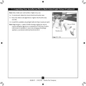
... Staked Light Fixture (Continued) Note: Glass shade style and number of 190 Watts. Thumbscrews Shade Bulb Steps 7-7 - 7-8 11 42686-01 • 01/07/09 • Hunter Fan Company Raise the shade to a maximum of lights may vary. 7-6. Further information is available at: www1.eere.energy.gov/buildings/ appliance_standards/residential/torchieres.html. Note...
... Staked Light Fixture (Continued) Note: Glass shade style and number of 190 Watts. Thumbscrews Shade Bulb Steps 7-7 - 7-8 11 42686-01 • 01/07/09 • Hunter Fan Company Raise the shade to a maximum of lights may vary. 7-6. Further information is available at: www1.eere.energy.gov/buildings/ appliance_standards/residential/torchieres.html. Note...

Owner's Manual
Page 12
...and on the wall. To dim the Low light, hold the light button down until you can mount the remote holder to turn the fan off. 9-5. Press the OFF button to full brightness. When necessary, replace the battery with the screws already in the switch plate. You...to any toggle switch plate with a 12-volt type 23A, MN-21 battery or equivalent. 9-6. For best operation, start the fan by pressing high, then select Fan Speed High your desired brightness. Fan Speed Medium Fan Off Fan Light Steps 9-1 - 9-4 Step 9-6 12 42686-01 • 01/07/09 • Hunter Fan Company Step 9-5
...and on the wall. To dim the Low light, hold the light button down until you can mount the remote holder to turn the fan off. 9-5. Press the OFF button to full brightness. When necessary, replace the battery with the screws already in the switch plate. You...to any toggle switch plate with a 12-volt type 23A, MN-21 battery or equivalent. 9-6. For best operation, start the fan by pressing high, then select Fan Speed High your desired brightness. Fan Speed Medium Fan Off Fan Light Steps 9-1 - 9-4 Step 9-6 12 42686-01 • 01/07/09 • Hunter Fan Company Step 9-5

Owner's Manual
Page 13
...switch on electrical power to prevent scratching. For cleaning finishes, use upward air flow pattern 13 42686-01 • 01/07/09 • Hunter Fan Company A vacuum cleaner brush nozzle can remove heavier dust. Clean wood finish blades with a direct breeze. Reversing Switch In cold weather, use...a mild detergent and a slightly dampened cloth. In warm weather, use an artistic agent, but never abrasive cleaning agents as the fan finish. Restart fan. Clean painted and high-gloss blades in warm weather to a complete stop. You may use downward air flow pattern To Change ...
...switch on electrical power to prevent scratching. For cleaning finishes, use upward air flow pattern 13 42686-01 • 01/07/09 • Hunter Fan Company A vacuum cleaner brush nozzle can remove heavier dust. Clean wood finish blades with a direct breeze. Reversing Switch In cold weather, use...a mild detergent and a slightly dampened cloth. In warm weather, use an artistic agent, but never abrasive cleaning agents as the fan finish. Restart fan. Clean painted and high-gloss blades in warm weather to a complete stop. You may use downward air flow pattern To Change ...
Owner's Manual
Page 14
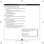
...enclosed balancing kit and instructions to the wiring the fan section. 3. Turn power on the light socket. Loosen canopy, check all connections according to balance the fan. 2. Problem: Lights dim when turned on or do not turn on . 6. Hunter Fan Company 2500 Frisco Avenue Memphis, Tennessee 38114 14... 42686-01 • 01/07/09 • Hunter Fan Company Check the plug connection in the switch housing. ...
...enclosed balancing kit and instructions to the wiring the fan section. 3. Turn power on the light socket. Loosen canopy, check all connections according to balance the fan. 2. Problem: Lights dim when turned on or do not turn on . 6. Hunter Fan Company 2500 Frisco Avenue Memphis, Tennessee 38114 14... 42686-01 • 01/07/09 • Hunter Fan Company Check the plug connection in the switch housing. ...

Parts Guide
Page 1
...Assembly Screw, Machine, 6-32 Wire Connector Mounting Isolator Thumbscrew Bulb Balancing Kit Remote Control Receiver Remote Control Transmitter Model # Asm. Dwg. # Finish Qnty 22434 93889-01 White Part # 96794-03 22435 93889-02 Antique Brass Part # 96794-05 22436 93889-03 Bright Brass Part # 96794-01 1 98950-03... 4 77646-04 77646-04 77646-04 1 07570-01 07570-01 07570-01 1 85068-02 85068-02 85068-02 1 85094-01 85094-01 85094-01 Hunter Fan Company • 2500 Frisco Avenue • Memphis, TN 38114 • www.hunterfan.com • 98000-01-303 12-25-2008 • ©...
...Assembly Screw, Machine, 6-32 Wire Connector Mounting Isolator Thumbscrew Bulb Balancing Kit Remote Control Receiver Remote Control Transmitter Model # Asm. Dwg. # Finish Qnty 22434 93889-01 White Part # 96794-03 22435 93889-02 Antique Brass Part # 96794-05 22436 93889-03 Bright Brass Part # 96794-01 1 98950-03... 4 77646-04 77646-04 77646-04 1 07570-01 07570-01 07570-01 1 85068-02 85068-02 85068-02 1 85094-01 85094-01 85094-01 Hunter Fan Company • 2500 Frisco Avenue • Memphis, TN 38114 • www.hunterfan.com • 98000-01-303 12-25-2008 • ©...


